

The brain child of H. P. Folland and Major Frank Widenham Goodden, the SE 5 airframe was modified after the initial batch of 24 (A4845 - A4868.) It was in the middle of the second production batch (A8898 - A8947) that design alterations created the new designation SE 5a. Essentially shortened wings and revised aileron controls were incorporated. In the matter of aircraft nomenclature it is of interest to note that the annotation of the Royal Aircraft Factory drawings states that it was modifications to the mainplane that distinguished the SE 5a from the SE 5. But in the Air Board technical notes are headed; (I) SE 5a, 200hp Hispano - Suiza (II) SE 5, 150hp Hispano - Suiza. The first production SE 5a was A8923.
As a model, it has been a favorite subject for many years. The basic kits that were available were the venerable Aurora and the Lindberg kits. Rodens contributions began arriving and all that we knew changed.
In October 2003. 1/72, 49 piece version was issued.
In late Sept. 2004 the 1/48 kit 416 (depicting the Wolseley Viper version) with 91 piece version arrived.
Then in late June. 2005, 1/48 kit #419 (depicting the Hispano - Suiza version) also with 91 piece version arrived.
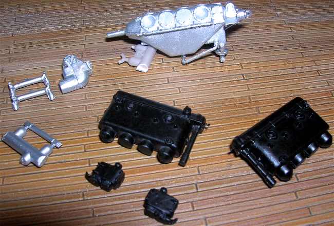
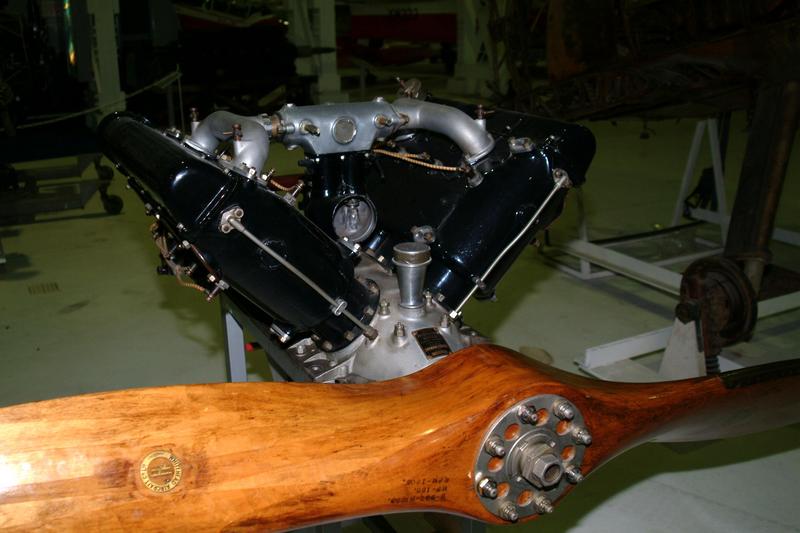
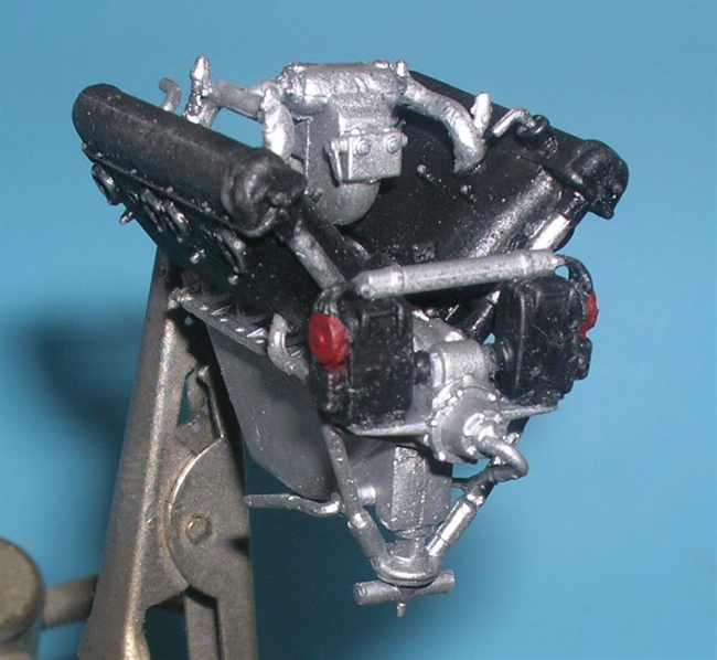
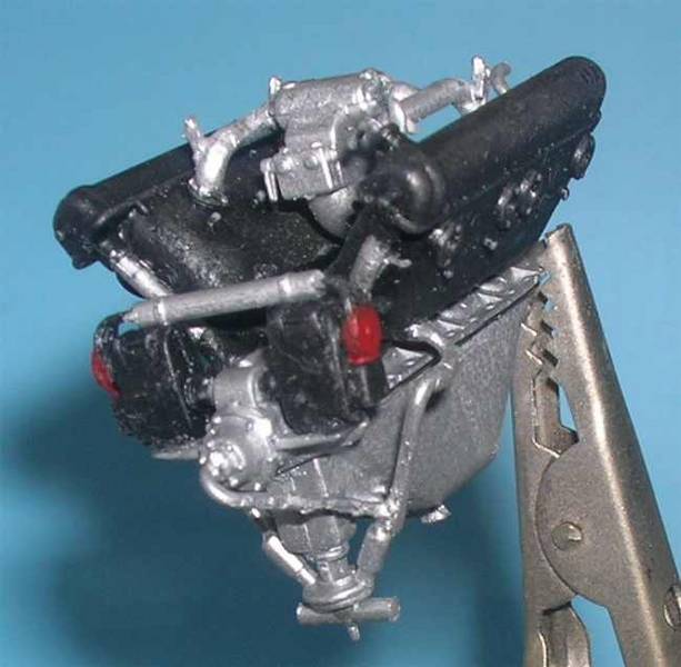
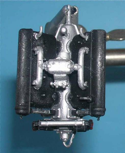
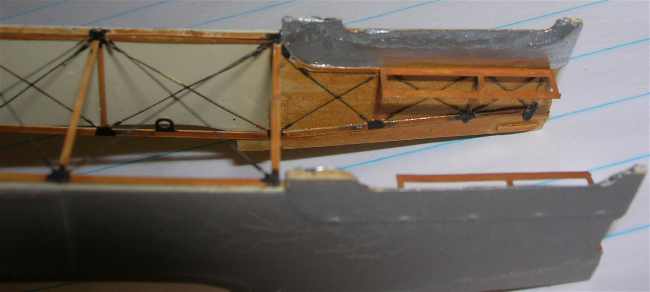
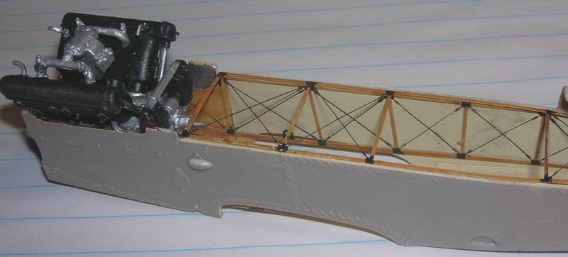
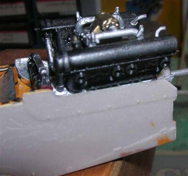
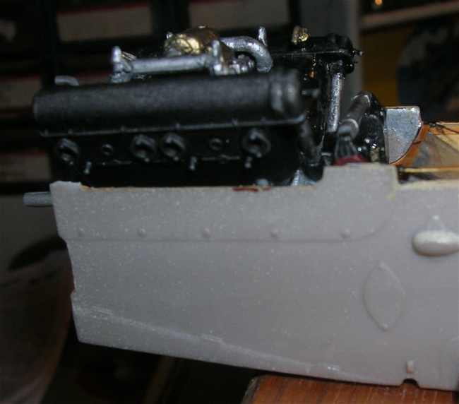
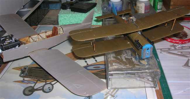
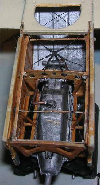
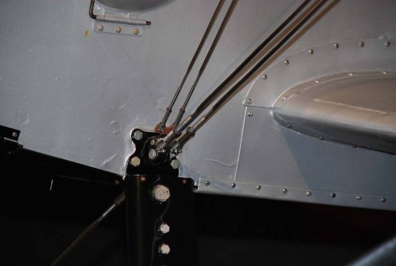
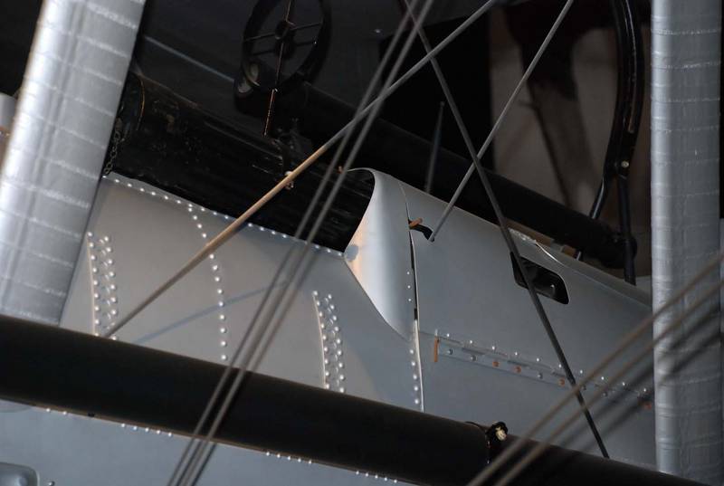
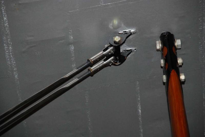
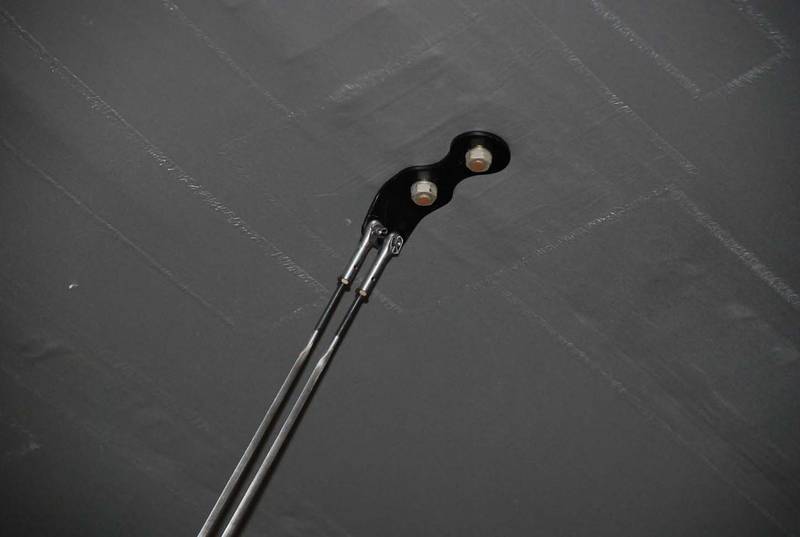
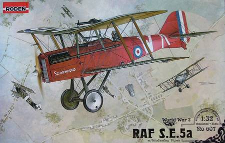
Finally in May 2007 the 1/32 kit #607 was delivered to the worlds local hobby shops. It also has decals and profiles for the late version airframe with the Wolseley Viper engine. Yet this kit differs from the other Roden SE 5a kits in that it does have the full engine present. The subtle detail contributes greatly to the over-all look. First if you want to rig this kit, you should plot all the rigging lines and strut locator holes you will need to work with. Planning ahead using references and plan views will ensure your success. Pre-drill all pilot holes for each end of the struts and the rigging wires. Dont be afraid to take notes. There should be two holes for each wire and each strut. Drill the strut locator and rigging holes.
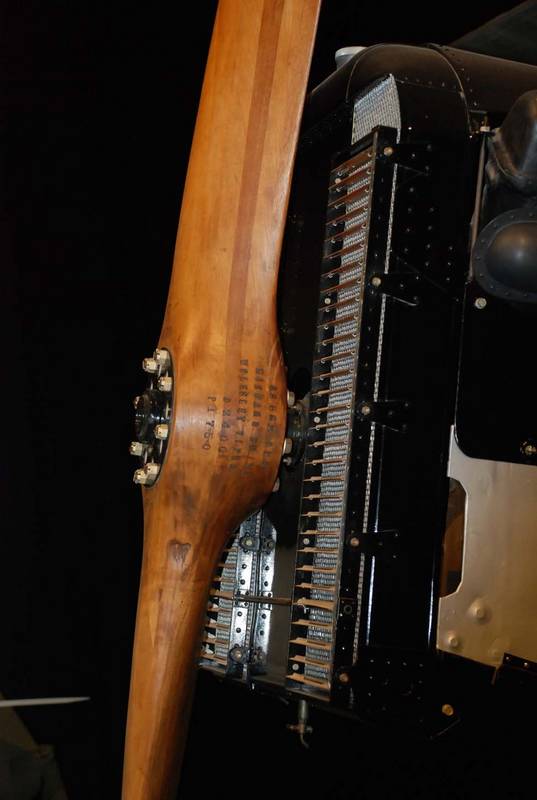
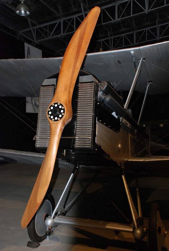
The instructions begin with assembling parts for Rodens 200hp Wolseley W.4a Viper. Note parts for the 200 - 220hp Hispano- Suiza engine are on the same parts tree.