

Early Aviation
Discuss World War I and the early years of aviation thru 1934.
Discuss World War I and the early years of aviation thru 1934.
Hosted by Jim Starkweather
KoTS GB 2011 Albatros D.III lcarroll
JackFlash

Joined: January 25, 2004
KitMaker: 11,669 posts
AeroScale: 11,011 posts
Posted: Tuesday, April 19, 2011 - 12:14 PM UTC
Lance right click on your image I posted and you will see how the brackets fall.
OEFFAG_153

Joined: February 19, 2010
KitMaker: 1,473 posts
AeroScale: 1,450 posts

Posted: Tuesday, April 19, 2011 - 08:03 PM UTC
Hi Lance,
Really nice work on the interior sorry about your troubles posting the images hope you get the hang of it soon I really would like to see more of this build.
Mikael
Really nice work on the interior sorry about your troubles posting the images hope you get the hang of it soon I really would like to see more of this build.
Mikael

thegirl

Joined: January 19, 2008
KitMaker: 6,743 posts
AeroScale: 6,151 posts
Posted: Wednesday, April 20, 2011 - 01:03 AM UTC
Hi Lance !
Very nicely done so far , I really like how the seat turned out as well
It can be a under taking up-loading pic's to the site . You will get the hang of it and will become second nature . It took me a while with great frustration ending in tears . A good friend ended up phoning me and walking me through it .
wing_nut
Joined: June 02, 2006
KitMaker: 1,212 posts
AeroScale: 468 posts
Posted: Wednesday, April 20, 2011 - 01:13 AM UTC
Looking good so far... nice interior.
For the photos, open a free account at Photobucket.com. Once the photos are uploaded all you have to do is hover you mouse over the photo you want and when the 4 lines of code appear click on the "IMG code" line at the bottom and it will automatically copy. Paste that into your post and you're all set.
For the photos, open a free account at Photobucket.com. Once the photos are uploaded all you have to do is hover you mouse over the photo you want and when the 4 lines of code appear click on the "IMG code" line at the bottom and it will automatically copy. Paste that into your post and you're all set.
Removed by original poster on 04/20/11 - 18:57:15 (GMT).
Removed by original poster on 04/20/11 - 19:08:25 (GMT).

lcarroll
Joined: July 26, 2010
KitMaker: 1,032 posts
AeroScale: 1,025 posts
Posted: Wednesday, April 20, 2011 - 08:24 AM UTC
Marc, (or anyone who can help!!)
I opened an account and loaded everything into Photo Bucket no problem. The photos were reduced previously to fit the file size stated on this site.
I then tried following your steps; best I can get is the dreaded box with a red X. ( is that normal ie. the photo will load later?)
When you paste it into the post I assume it's as Steven described in his earlier attempt to get me going .........that is left click on theIMG button far right, left click inside the brackets that appear saying put url image here etc. and hit paste. Then add your text and hit Yes (ready to reply button)
What am I missing or should I register for a Beginners Class for Computer Dummies?
This is getting "old' real fast now!
Lance
Kornbeef

Joined: November 06, 2005
KitMaker: 1,667 posts
AeroScale: 1,551 posts

Posted: Wednesday, April 20, 2011 - 08:48 AM UTC
Lance Photobucket, if its set up like mine,
Have your aeroscale post open and another tab with your photbucket album open
hover over the pic you want,
4 boxes should pop up under it.
Left click the bottom one marked (IMG Code) it should pop up a msg *copied*
Now swap tabs into Aeroscale
Ctl V where you want the pic, A line of text should appear with IMG at each end.
carry on with your post or add the next pic the same way.
(the images don't show till you post)
hit the yes button and see if it work.
Fingers crossed.
Keith.
lcarroll
Joined: July 26, 2010
KitMaker: 1,032 posts
AeroScale: 1,025 posts
Posted: Wednesday, April 20, 2011 - 09:46 AM UTC

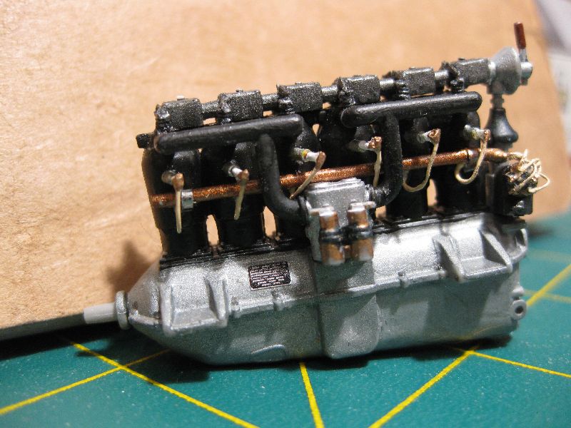
The DIII Mercedes at the initially finished stage. Next post will show the final steps complete including the mounting bolts etc detailed in the earlier thread narrative which I entered in the era I'm calling "Pre Help from all my kind new friends". Thanks to Steven, Mark, and particularly Keith who made this entry possible. You folks are wonderful....think I'm now in business!
The Carb float chambers will be re-aligned prior to dropping in a photo of the finished module mounted in the formers/frame.
Now I am having fun!!!!!
Cheers,
Lance
lcarroll
Joined: July 26, 2010
KitMaker: 1,032 posts
AeroScale: 1,025 posts
Posted: Wednesday, April 20, 2011 - 10:07 AM UTC

Close up of the incorrectly mounted (upside down) carb components picked up by Keith......saved me an ulcer later! Also will require some re-painting - amazing what these little digital cameras can catch.

Right side (Mounting bolts now installed and some oil/goo/dirt applied with Tamiya Smoke Acrylic wash.
lcarroll
Joined: July 26, 2010
KitMaker: 1,032 posts
AeroScale: 1,025 posts
Posted: Wednesday, April 20, 2011 - 02:50 PM UTC
One step closer to getting this post to where I'm at:

The engine now mounted in the former module. Weathering, hi-liting, and "dirtying up" applied. I did have a bit of a struggle with this step as the former assembly was not perfectly aligned. All was more or less tensioned back to (hopefully) true by doing the four lug attachments one at a time; lots of clamping, squeezing and thank Gawd for CA accelerator.
I painted all the lower former portions and the bottom of the mounts per the WNW Plan views of the engine assembly in their DVa Kit Plan Book with the "grey-green"interior color that I whipped up and labeled "Albatross grey green". I used a 50/50 mix of M.Master RLM 80 Olivgrun and their FS 35237 Medium Grey enamels and to my eye it matches pretty well.
Next I'll cover the module containing the fuel tank and ammo boxes.
lcarroll
Joined: July 26, 2010
KitMaker: 1,032 posts
AeroScale: 1,025 posts
Posted: Wednesday, April 20, 2011 - 03:32 PM UTC
Thought it an appropriate point to enter some info on my fist adventure into the wonderful world of woodgraining. I have spent days marveling at the various examples on the post; oils, hand-graining, sponges, acrylics, water colors, and a host of techniques. Some more appealing then others but WOW, what beautiful work!
For my first attempt I chose the water color thing, motivated above all else by a members comment to the effect that if you didn't like the outcome you could just wipe it off and try again. (I certainly exercised that concept to exhaustion!)
For this build I used a base coat of Humbrol Oak enamel followed by a streaking medium of Grumbacher Artists Watercolor (Tubes). The main color used was their Raw Sienna with a little Yellow Ochre for darker effects. For the exterior I'll be applying some degree of clear yellow or orange to produce the "tone" desired.


The photos illustrate my results which I am happy with as a first try.
Technique employed was to apply lines of the unthinned watercolor and immediately start blending it with a stiff dry artists brush. You can take it thinner and thinner, manipulate the direction of the grain, and I found add more where desired and work it in. Once satisfied with the result I airbrushed a very thinned down Future mix over all.
All but the completely visually impaired will immediately note the unfilled ejector pin marks in the photos. My logic was that they would be covered by the various components once assembled................ the one below the throttle now has my concern big time. I may have to scratch build an article of clothing, errant map, or something equally ridiculous to cover that short cut!
More in the next few days.....
Cheers
For my first attempt I chose the water color thing, motivated above all else by a members comment to the effect that if you didn't like the outcome you could just wipe it off and try again. (I certainly exercised that concept to exhaustion!)
For this build I used a base coat of Humbrol Oak enamel followed by a streaking medium of Grumbacher Artists Watercolor (Tubes). The main color used was their Raw Sienna with a little Yellow Ochre for darker effects. For the exterior I'll be applying some degree of clear yellow or orange to produce the "tone" desired.
The photos illustrate my results which I am happy with as a first try.
Technique employed was to apply lines of the unthinned watercolor and immediately start blending it with a stiff dry artists brush. You can take it thinner and thinner, manipulate the direction of the grain, and I found add more where desired and work it in. Once satisfied with the result I airbrushed a very thinned down Future mix over all.
All but the completely visually impaired will immediately note the unfilled ejector pin marks in the photos. My logic was that they would be covered by the various components once assembled................ the one below the throttle now has my concern big time. I may have to scratch build an article of clothing, errant map, or something equally ridiculous to cover that short cut!
More in the next few days.....
Cheers
Kornbeef
Joined: November 06, 2005
KitMaker: 1,667 posts
AeroScale: 1,551 posts
Posted: Wednesday, April 20, 2011 - 08:22 PM UTC
Lance, you said:-
All but the completely visually impaired will immediately note the unfilled ejector pin marks in the photos. My logic was that they would be covered by the various components once assembled................ the one below the throttle now has my concern big time. I may have to scratch build an article of clothing, errant map, or something equally ridiculous to cover that short cut!
Try dryfitting the cockpit unit in the fuselage and pop the coaming on too, see how little you can actually see. the angle of sight is quite narrow and the Magneto switch might well cover it enough, of course you will have *but I know it's there* syndrome.
The wood grain looks pretty good, I'd be happy with it. I would catch the edges of the framework though with a little darker colour before you button her up.
Keith.

Mgunns
Joined: December 12, 2008
KitMaker: 1,423 posts
AeroScale: 1,319 posts

Posted: Thursday, April 21, 2011 - 01:09 AM UTC
Your wood really turned out nice. I would go with Keith's assessment. You may be surprised at how unobtrusive that ejector mark is. You know it's there, but to all but the very erudite, it would appear as if it was part of the program.
Looking forward to more.
Best
Mark
Looking forward to more.
Best
Mark
lcarroll
Joined: July 26, 2010
KitMaker: 1,032 posts
AeroScale: 1,025 posts
Posted: Thursday, April 21, 2011 - 03:01 AM UTC
Quoted Text
Your wood really turned out nice. I would go with Keith's assessment. You may be surprised at how unobtrusive that ejector mark is. You know it's there, but to all but the very erudite, it would appear as if it was part of the program.
Looking forward to more.
Best
Mark
Thanks for the encouraging and kind words. Agree with both of you and will be adding the darker hilite to the frame longerons etc. before the button up stage.

This photo supports Keiths theory regarding covering up the ejector pin hole. Taken during an earlier dry fit before I re-cut the floor from the DII to the real DIII config and added the key and chain etc. Just might get away with it! (Dealing with the "I know it's there" thing will be a test of my mental stability!)
May be a day or so before the next update; the Power Company is providing me with a 6-8 hour power outage today for some maintenance on the grid so the cave may be a little dark for any work most of today.
On the brighter side I can devote some time to thinking through the assembly sequence; getting the flight control cables and various cockpit components/controls completed while still accesable is going to be a challenge but one I'm looking forward to.
By the way, the dog hair just below the mag has been removed since; just love the little guy but I think the bench area is going to be out of bounds in future.
Cheers,
Lance
thegirl
Joined: January 19, 2008
KitMaker: 6,743 posts
AeroScale: 6,151 posts
Posted: Friday, April 22, 2011 - 02:07 AM UTC
So far Lance your build is coming along very well ! Those spark plugs are just so cool  I use a bit of the PE parts from the model cars . Nut's and bolts with washers and all the other odd shapes really come in handy for detailing .
Looking forward to your next up-date !
I use a bit of the PE parts from the model cars . Nut's and bolts with washers and all the other odd shapes really come in handy for detailing . Looking forward to your next up-date !
lcarroll
Joined: July 26, 2010
KitMaker: 1,032 posts
AeroScale: 1,025 posts
Posted: Friday, April 22, 2011 - 11:12 AM UTC
Quoted Text
So far Lance your build is coming along very well ! Those spark plugs are just so cool
Looking forward to your next up-date !
Thanks Terri!
The bolts I have been using are from old 1/48th PE sets and also VectorNuts. Next trip to civilization I'll be checking out some of the Car stuff, great idea.
Next update within the hour; the power outage I mentioned "fried"my Internet router so tha last 24 hours has been eaten up with getting that situation fixed.
Cheers,
Lance
lcarroll
Joined: July 26, 2010
KitMaker: 1,032 posts
AeroScale: 1,025 posts
Posted: Friday, April 22, 2011 - 12:16 PM UTC
Next in the build sequence, the Fuel and ammunition containers module. This phase went quite smoothly, the basic components being well produced by Roden.


Two views of the initial completion stage. The Eduard DIII PE Set really enhanced the resulls, highly recommend it. The containers were painted with various tone mixes of Humrol flat aluminum, some details picked out with lightened gunmetal and a satin overcoat (M.Master) applied.

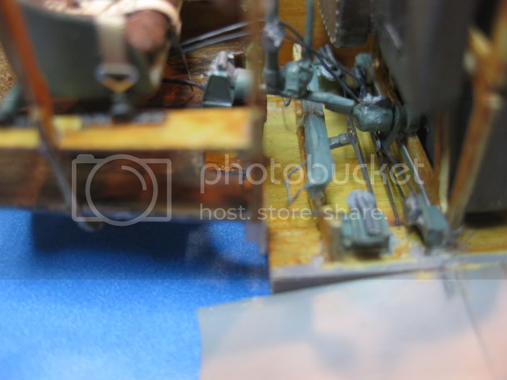
The next step was to add the flight control components to the former. Some serious study of Koloman Meyerhofer's Replica build provided outstanding views of the lay out. Scratch built pulleys were added to the bottom of the former for the aileron controls followed by the metal braciing and then a similarly produced mount and pulleys for the control stick assembly to be slid into and attached once the cockpit module gets added. Finally the control cables were attached (6 pound test fishing line) painted with thinned M.Master engine grey enamel.


At this stage some brown "gunge"wash was applied to provide a little worn/used effect. Last, the rudder cable assembly was added to the bottom wing; The pencil line will be just hidden by the Fuel/Ammo bottom frame when added. The very delicate (and presently bent!) rudder pedal foot/heel rests will be straightened just prior to attachment to the fuselage assembly.


I am probably going to remove the PE "face" on the rudder bar and add the heel rests separately.not at all pleased with the messy appearance due to bad positioning and too much CA.
At this stage I'm ready to tackle completion of the the cockpit module and trying to get my head around the assembly sequence. Will need to tension and attach the control cables prior to buttoning her up, probably by attaching all the modules to the left fuselage side which will also leave access for the throttle linkage, wiring etc.
To this point a very enjoyable build, I really like this kit but she's a slow go.
Two views of the initial completion stage. The Eduard DIII PE Set really enhanced the resulls, highly recommend it. The containers were painted with various tone mixes of Humrol flat aluminum, some details picked out with lightened gunmetal and a satin overcoat (M.Master) applied.
The next step was to add the flight control components to the former. Some serious study of Koloman Meyerhofer's Replica build provided outstanding views of the lay out. Scratch built pulleys were added to the bottom of the former for the aileron controls followed by the metal braciing and then a similarly produced mount and pulleys for the control stick assembly to be slid into and attached once the cockpit module gets added. Finally the control cables were attached (6 pound test fishing line) painted with thinned M.Master engine grey enamel.
At this stage some brown "gunge"wash was applied to provide a little worn/used effect. Last, the rudder cable assembly was added to the bottom wing; The pencil line will be just hidden by the Fuel/Ammo bottom frame when added. The very delicate (and presently bent!) rudder pedal foot/heel rests will be straightened just prior to attachment to the fuselage assembly.
I am probably going to remove the PE "face" on the rudder bar and add the heel rests separately.not at all pleased with the messy appearance due to bad positioning and too much CA.
At this stage I'm ready to tackle completion of the the cockpit module and trying to get my head around the assembly sequence. Will need to tension and attach the control cables prior to buttoning her up, probably by attaching all the modules to the left fuselage side which will also leave access for the throttle linkage, wiring etc.
To this point a very enjoyable build, I really like this kit but she's a slow go.
lcarroll
Joined: July 26, 2010
KitMaker: 1,032 posts
AeroScale: 1,025 posts
Posted: Sunday, April 24, 2011 - 08:10 AM UTC
Only minor construction progress this weekend. Have been surfing the net for info and checking References to ensure the various modules are done to a reasonable level of what's possible for a fat fingered vision deteriorated old fella and getting great help from Kornbeef on an engine detail question (See my plea for help on Air Pump Details from earlier)
I've done a bunch of dry fitting, am adding a few more details to the engine and cockpit fuel control panel and, once done, will post some more photos, hopefully later tomorrow. For now it's off to the Daughter's for an Easter Sunday dinner (Dratted interuptions!)
Cheers,
Lance
I've done a bunch of dry fitting, am adding a few more details to the engine and cockpit fuel control panel and, once done, will post some more photos, hopefully later tomorrow. For now it's off to the Daughter's for an Easter Sunday dinner (Dratted interuptions!)
Cheers,
Lance
Kornbeef
Joined: November 06, 2005
KitMaker: 1,667 posts
AeroScale: 1,551 posts
Posted: Sunday, April 24, 2011 - 08:26 AM UTC
All things considered she is coming along just great Lance. Enjoy your easter dinner... 
lcarroll
Joined: July 26, 2010
KitMaker: 1,032 posts
AeroScale: 1,025 posts
Posted: Tuesday, April 26, 2011 - 11:07 AM UTC
I got quite a bit done over the past several days; time for and update.
The three modules of Engine, Fuel/Ammo, and Cockpit have been completed with very minor exceptions and are mounted in the left fuselage half. Prior to module installation the longerons etc. were given a subtle hilite with a thin wash of Burnt Sienna water color and blended. This assembly sequence was the only one I could imagine working given I wanted to install all of the flight control cables.

Cockpit and Ammo/Fuel Modules
The first module installed was the cockpit. Once the lower wing was attached complete with the rudder and aileron controls plus the cables the spark arrestor control rod and the wire from the magneto were installed. The complete module was then glued into place.
Next the completed Fuel tank and Ammunition boxes component was intalled into the fuselage half. With that in place the control stick could then be mounted to the base plate and swivel installed earlier on the aft former.

The next step was routing and tensioning of the rudder control cables followed by the installation of the control stick. Elevator control cables were routed from their forward pulley, over the guides on the stick and then aft under the seat. the return cables from the aft pulley point on the floor just ahead of the seat were rigged in a similar manner. Overall the rigging of the control cables was very much worth the effort however it took several hours to copmplete due to the cramped quarters and more then a modicum of "peripheral damage" from big finger impacts that had to be re-done.


Engine Module.
Once the dreaded air pump and plumbing were sorted out, scratch built, and installed the module was glued into place with CA on the major attachment points. This phase of the construction brought to light several shortfalls of the kit. The engine former/mount assembly needs to be built absolutely square to fit properly, mine wasn't and had to be "cracked", re-aligned, and the formers significantly trimmed down to fit snugly. Further, dry fitting of the right fuselage half revealed that the left member was slightly warped at the very front,; not enough to be a show stopper but final button-up will require some serious glue joints and added shims/contact points to ensure a permanent bond of the halves.


At this stage my computer is starting to act up so I'll close, clear, and continue in a few minutes assuming it isn't a terminal illness!
The three modules of Engine, Fuel/Ammo, and Cockpit have been completed with very minor exceptions and are mounted in the left fuselage half. Prior to module installation the longerons etc. were given a subtle hilite with a thin wash of Burnt Sienna water color and blended. This assembly sequence was the only one I could imagine working given I wanted to install all of the flight control cables.
Cockpit and Ammo/Fuel Modules
The first module installed was the cockpit. Once the lower wing was attached complete with the rudder and aileron controls plus the cables the spark arrestor control rod and the wire from the magneto were installed. The complete module was then glued into place.
Next the completed Fuel tank and Ammunition boxes component was intalled into the fuselage half. With that in place the control stick could then be mounted to the base plate and swivel installed earlier on the aft former.
The next step was routing and tensioning of the rudder control cables followed by the installation of the control stick. Elevator control cables were routed from their forward pulley, over the guides on the stick and then aft under the seat. the return cables from the aft pulley point on the floor just ahead of the seat were rigged in a similar manner. Overall the rigging of the control cables was very much worth the effort however it took several hours to copmplete due to the cramped quarters and more then a modicum of "peripheral damage" from big finger impacts that had to be re-done.
Engine Module.
Once the dreaded air pump and plumbing were sorted out, scratch built, and installed the module was glued into place with CA on the major attachment points. This phase of the construction brought to light several shortfalls of the kit. The engine former/mount assembly needs to be built absolutely square to fit properly, mine wasn't and had to be "cracked", re-aligned, and the formers significantly trimmed down to fit snugly. Further, dry fitting of the right fuselage half revealed that the left member was slightly warped at the very front,; not enough to be a show stopper but final button-up will require some serious glue joints and added shims/contact points to ensure a permanent bond of the halves.
At this stage my computer is starting to act up so I'll close, clear, and continue in a few minutes assuming it isn't a terminal illness!
lcarroll
Joined: July 26, 2010
KitMaker: 1,032 posts
AeroScale: 1,025 posts
Posted: Tuesday, April 26, 2011 - 12:03 PM UTC
Pre Button-Up Update, Part II (Computer has rested and is behaving again!)
Having reached this stage I am happy with the results. She's starting to look like she'll be a completed model eventually and somewhat like an Albatros.


Prior to joining the fuselage halves I'll be adding a few misc. widgets to the cockpit; the aux. throttle, control stick throttle, and wires from the gun triggers to the left side and on the right the fuel control panel and it's drain cock and vent line. The two hand pumps will be installed after she's buttoned up.
So far no major sense of humour failures; still like the kit overall and I am looking forward to working on the exterior for a change of pace.
Cheers,
Lance
Having reached this stage I am happy with the results. She's starting to look like she'll be a completed model eventually and somewhat like an Albatros.
Prior to joining the fuselage halves I'll be adding a few misc. widgets to the cockpit; the aux. throttle, control stick throttle, and wires from the gun triggers to the left side and on the right the fuel control panel and it's drain cock and vent line. The two hand pumps will be installed after she's buttoned up.
So far no major sense of humour failures; still like the kit overall and I am looking forward to working on the exterior for a change of pace.
Cheers,
Lance
Kornbeef
Joined: November 06, 2005
KitMaker: 1,667 posts
AeroScale: 1,551 posts
Posted: Tuesday, April 26, 2011 - 12:20 PM UTC
Coming along well there Lance, the issue with the engine mounts is a pretty universal Roden Albatros one so don't imagine its you.
I sent you a PM but looking at the pics I think it is a bit late...laughs, you steamed ahead faster than I thought. I suppose not everyone trudges along at my speed.
K
I sent you a PM but looking at the pics I think it is a bit late...laughs, you steamed ahead faster than I thought. I suppose not everyone trudges along at my speed.
K
lcarroll
Joined: July 26, 2010
KitMaker: 1,032 posts
AeroScale: 1,025 posts
Posted: Tuesday, April 26, 2011 - 01:59 PM UTC
Quoted Text
Coming along well there Lance, the issue with the engine mounts is a pretty universal Roden Albatros one so don't imagine its you.
I sent you a PM but looking at the pics I think it is a bit late...laughs, you steamed ahead faster than I thought. I suppose not everyone trudges along at my speed.
K
Keith,
The PM is great info; I'll send you my EMail Address for the photos you mentioned as they will be much appreciated. "Steaming along?", wait for it!
Remember I had some of the sub-components done prior to leaping with raw courage in my heart into the computer age and solving the obstacle of posting photos etc etc, with no small assistance from yourself I must add.
I now am working in real time; I suspect speed will be in the "Thomas the Train" category forthwith!!
Cheers,
Lance
Kornbeef
Joined: November 06, 2005
KitMaker: 1,667 posts
AeroScale: 1,551 posts
Posted: Tuesday, April 26, 2011 - 07:17 PM UTC
"Toot Toot" said Thomas happily. 
 |

WEB HOSTING BY


Copyright ©2021 AeroScale and Kitmaker Network, a subsidiary of Silver Star Enterprises
All Rights Reserved. Please read our Conditions of Use and Privacy Policy.
All Rights Reserved. Please read our Conditions of Use and Privacy Policy.