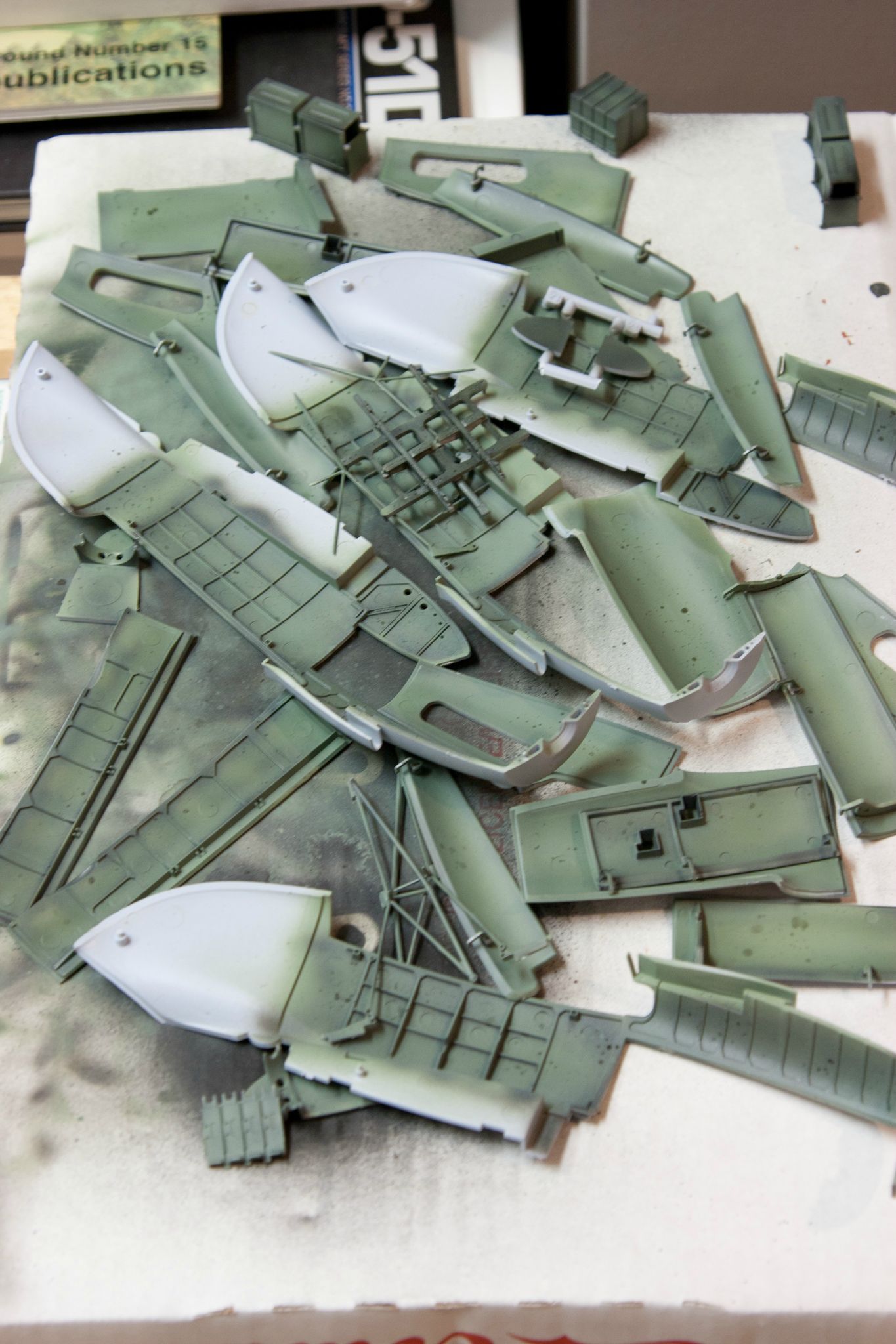
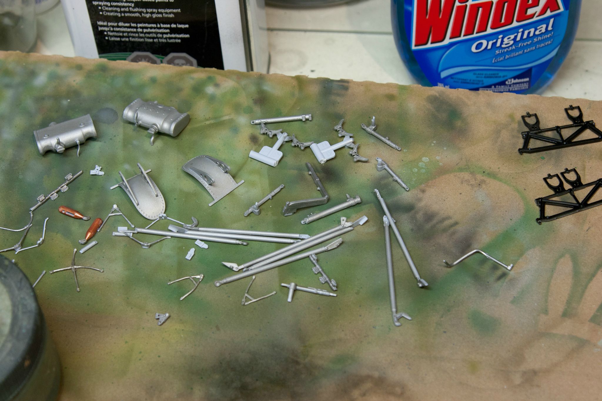
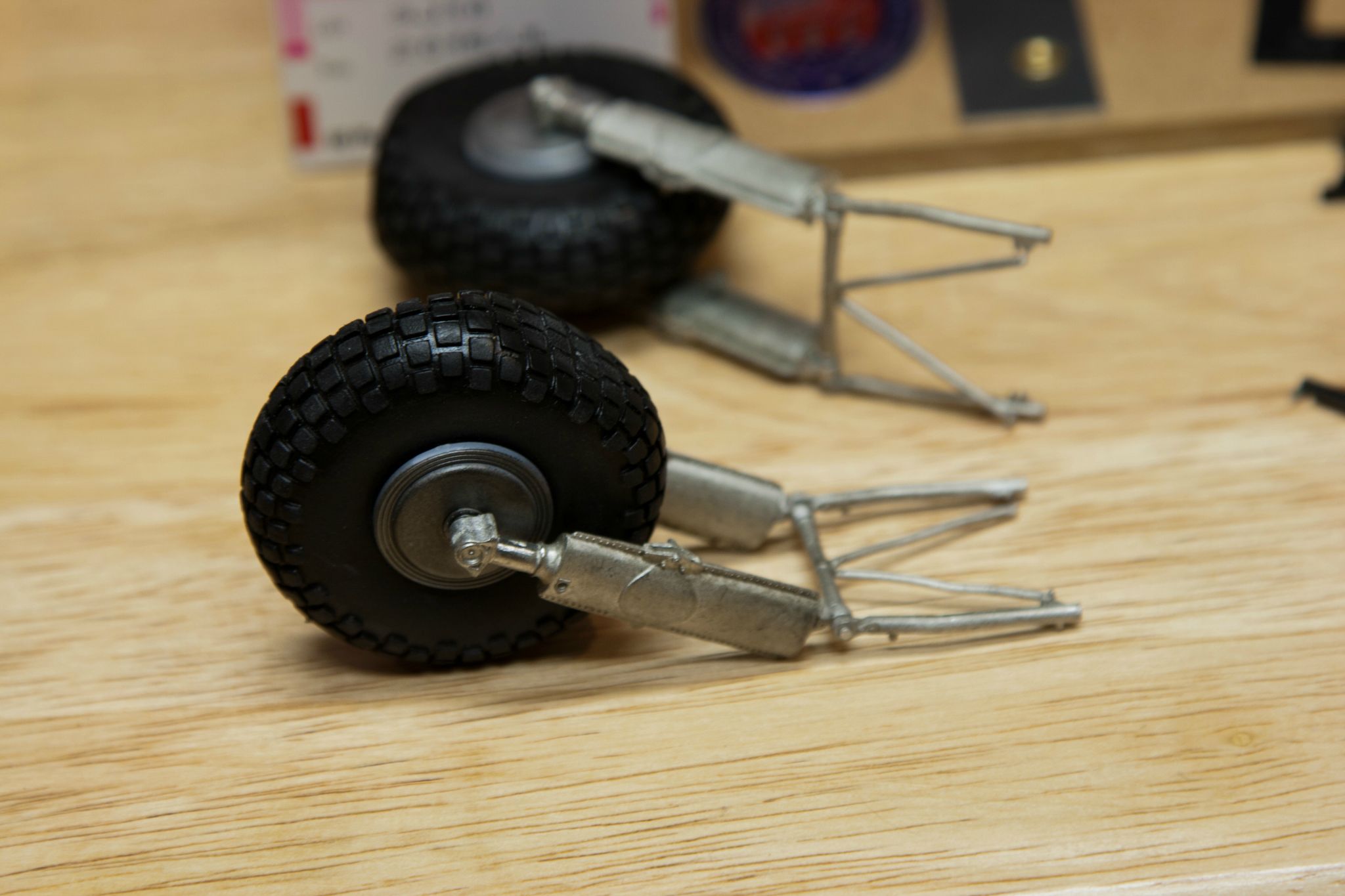
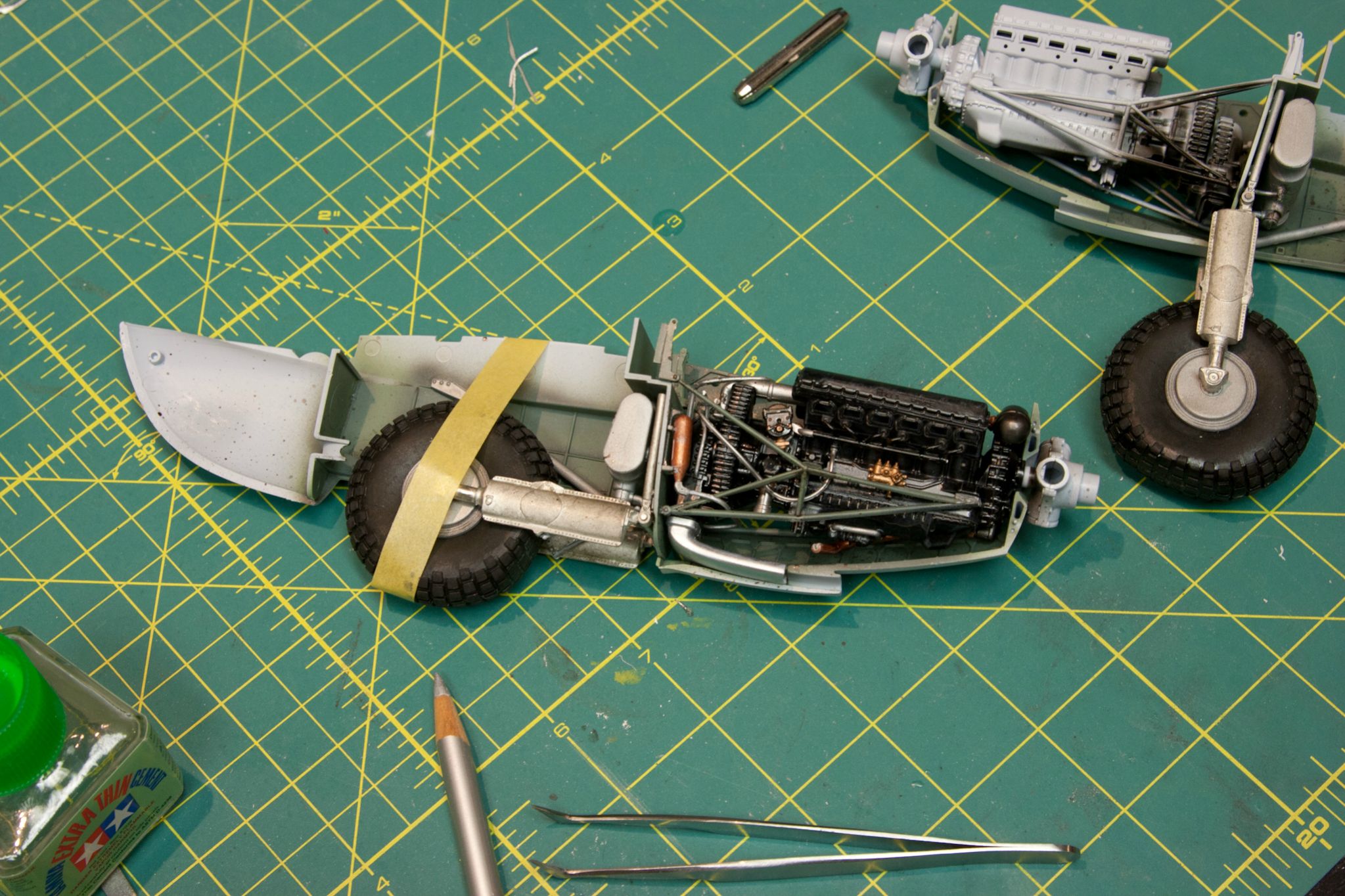
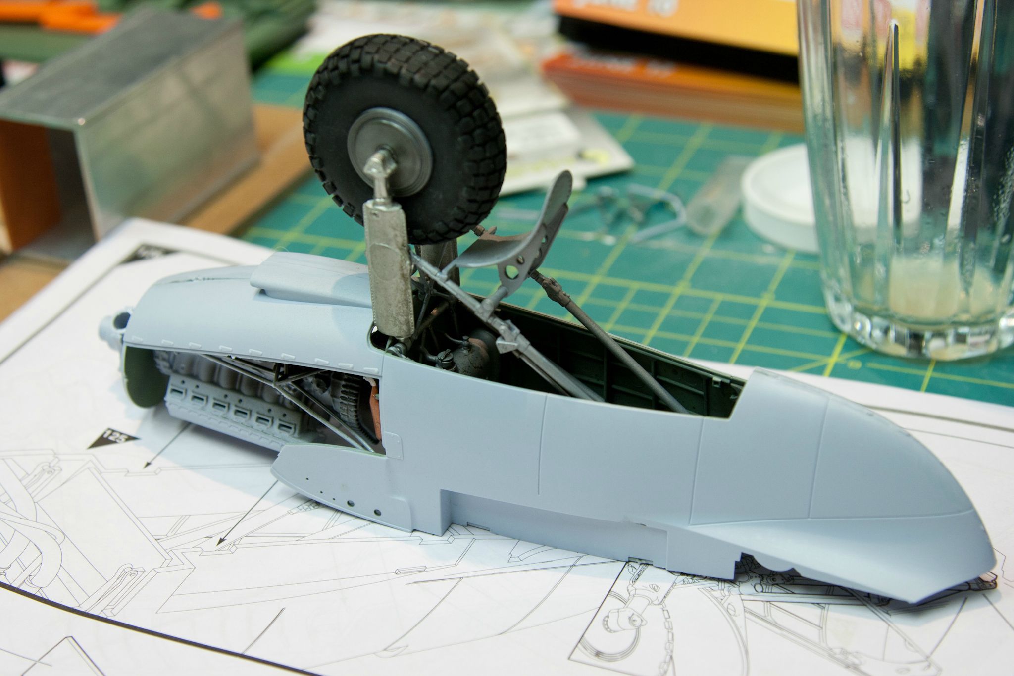
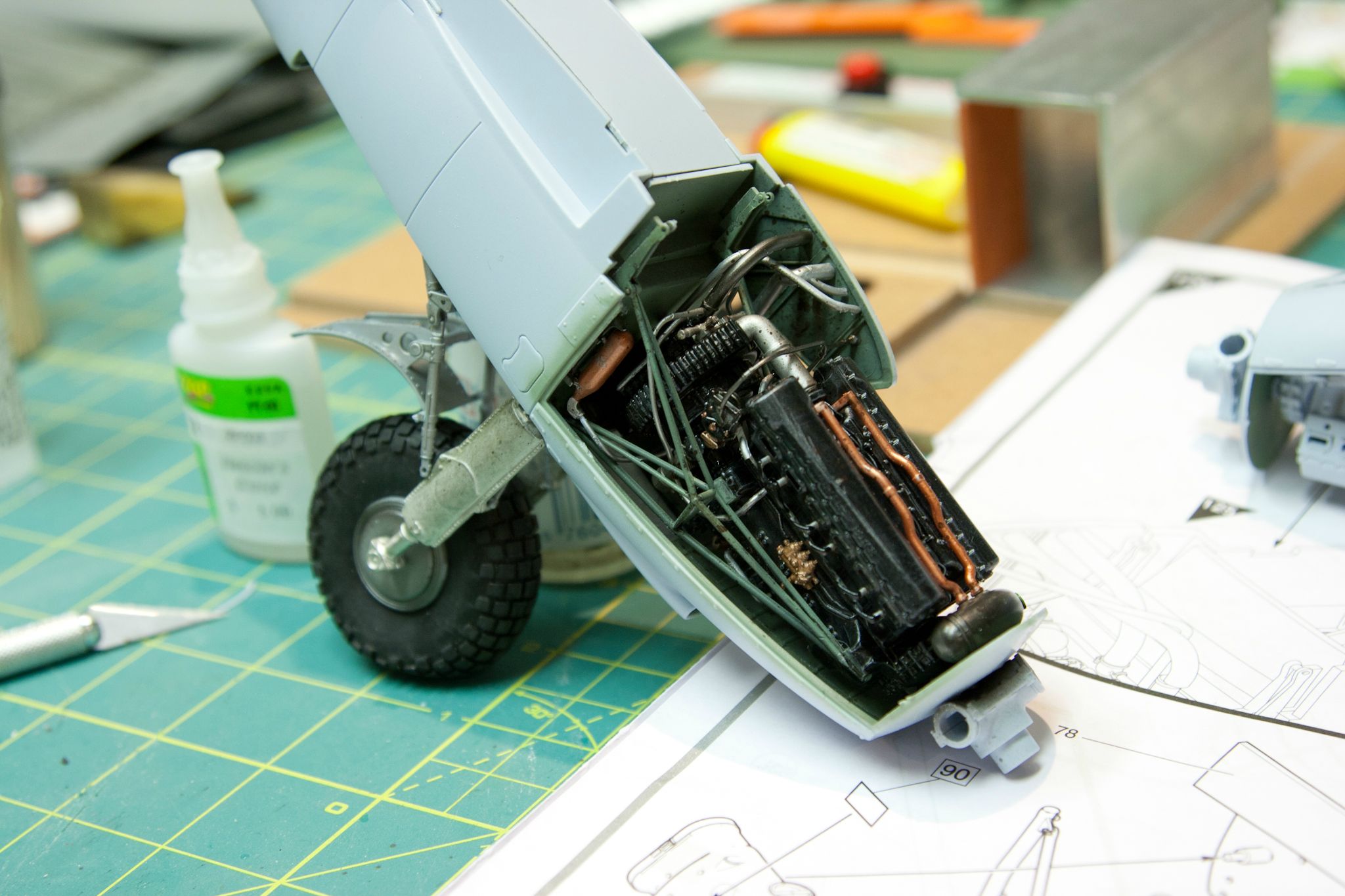
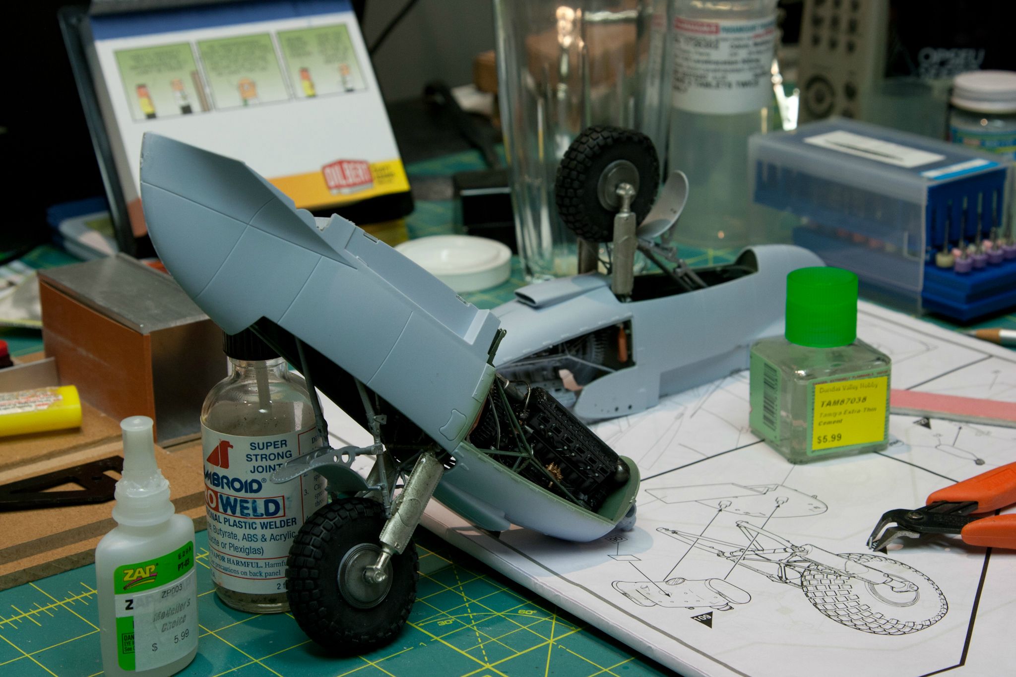
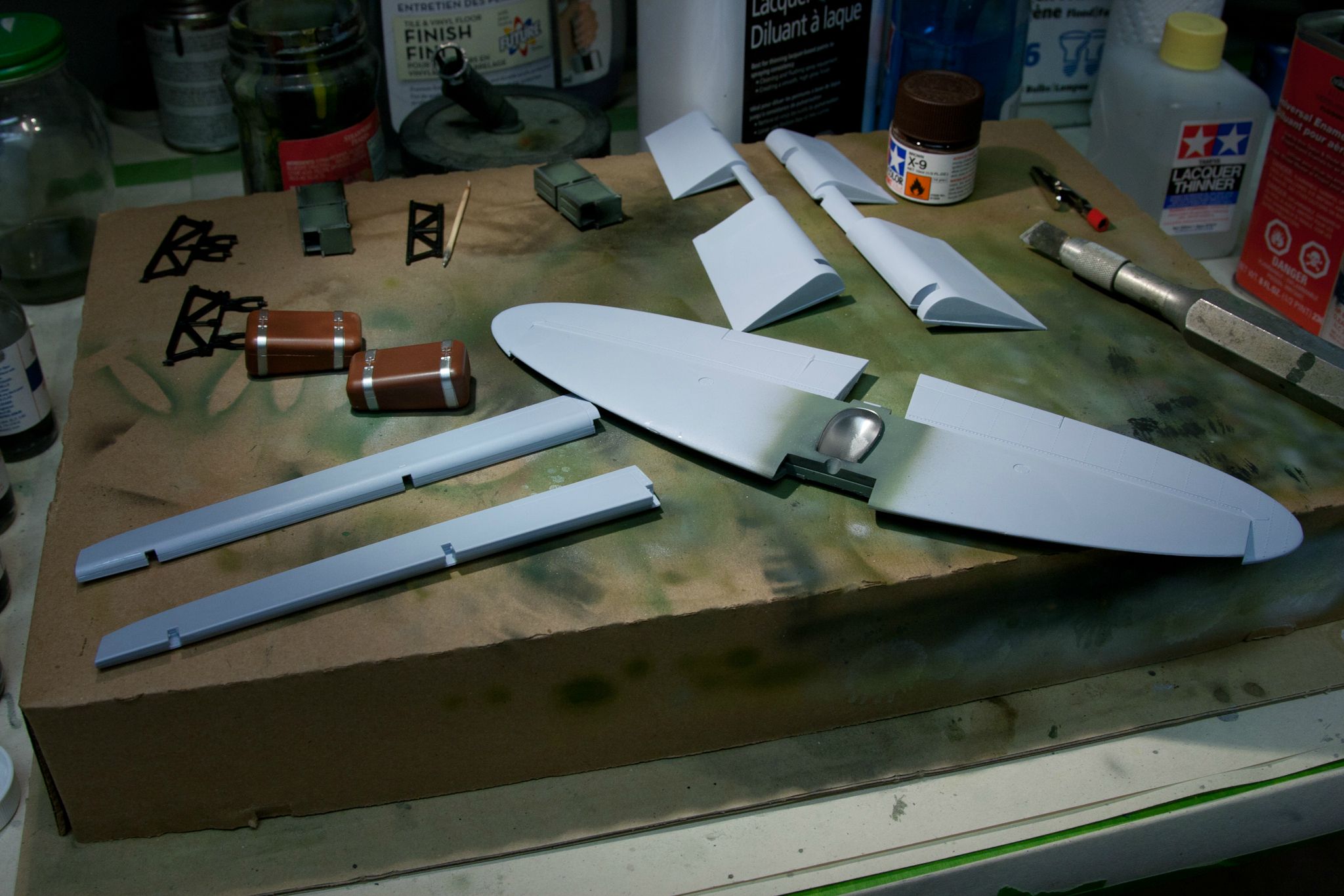
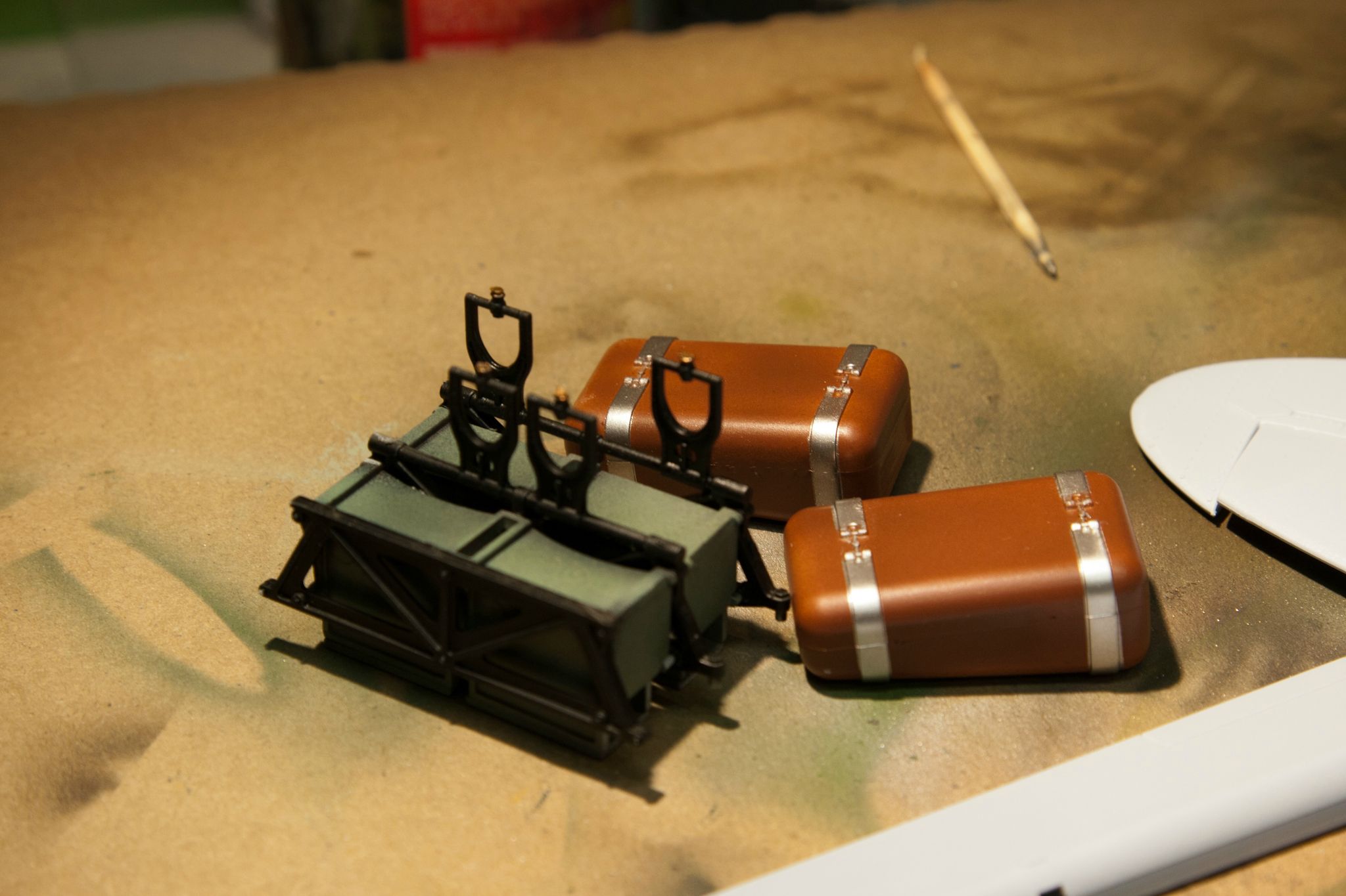
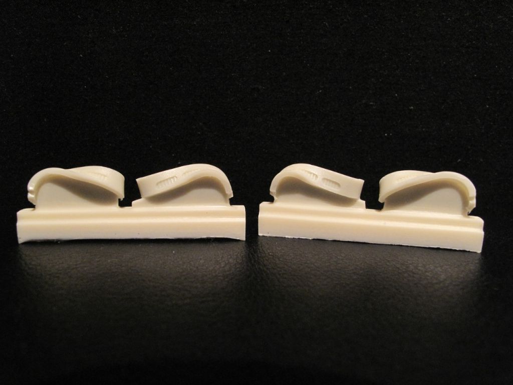
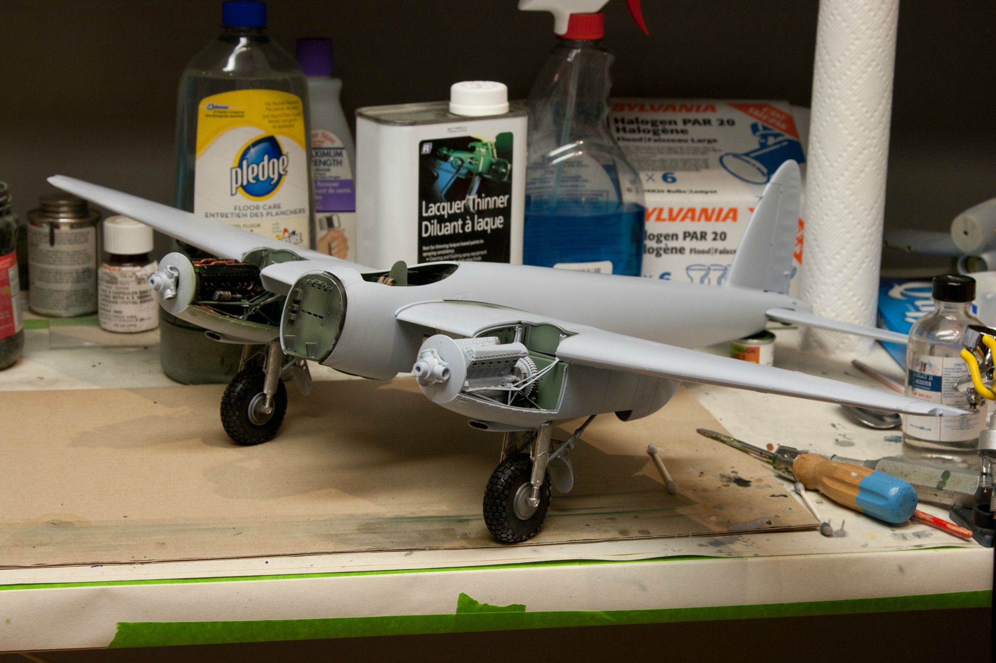
Well because things were moving along so well, it was only a matter of time until something went terribly wrong and after several hours of open heart surgery we're back on track.
I take half the blame for this, I misrouted the engine plumbing, but I did my due diligence and checked photos on every build thread around. I spent DAYS doing just this. I still place half the blame on airfix for their vague instructions and assemble by guess build process.
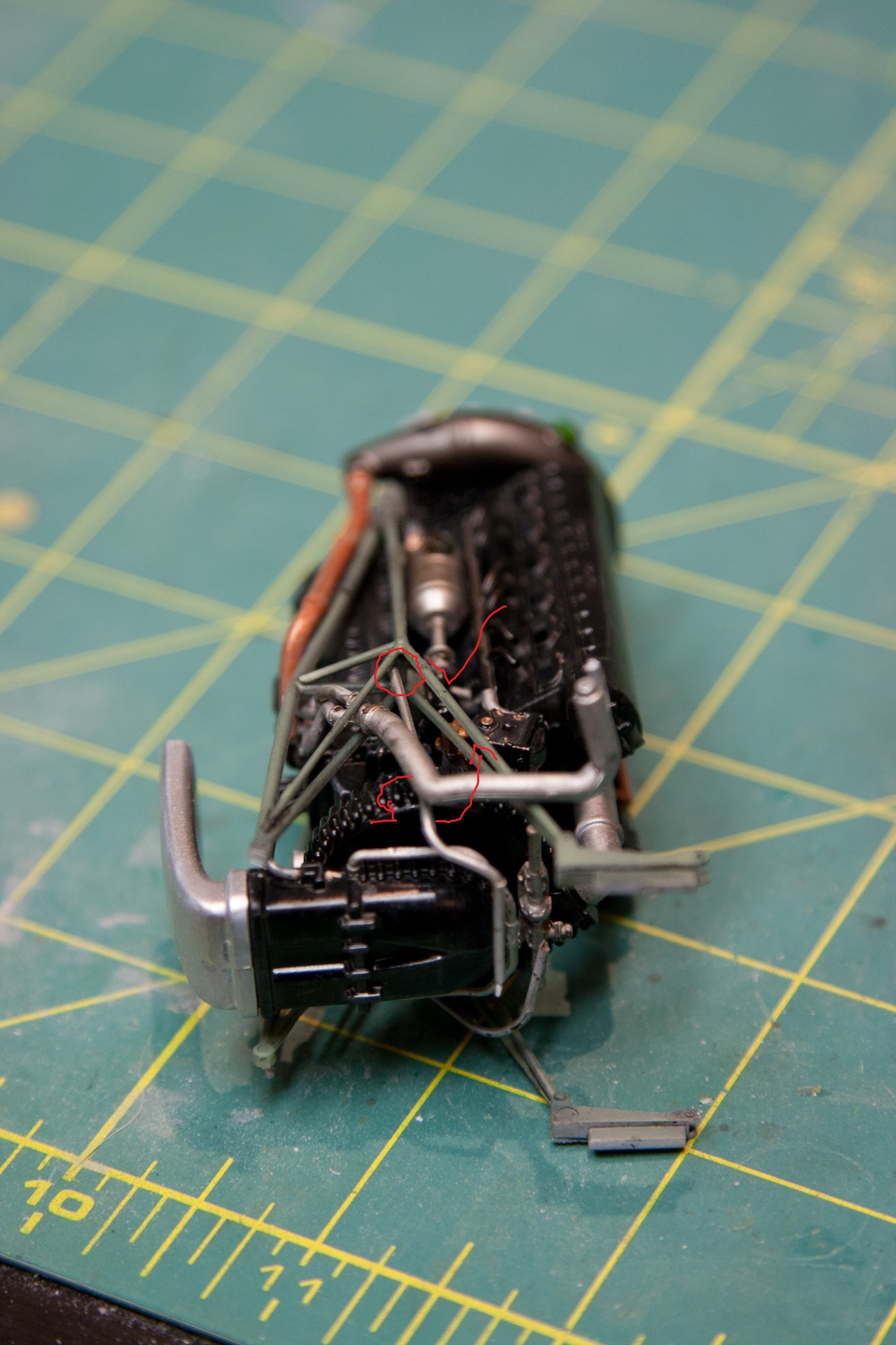
Please forgive my crude use of MSPaint in an effort to help illustrate what I'm talking about.
Now I don't claim to be more than an average builder at best, and this is a rookie mistake, but like I said - I thought I had done my homework.
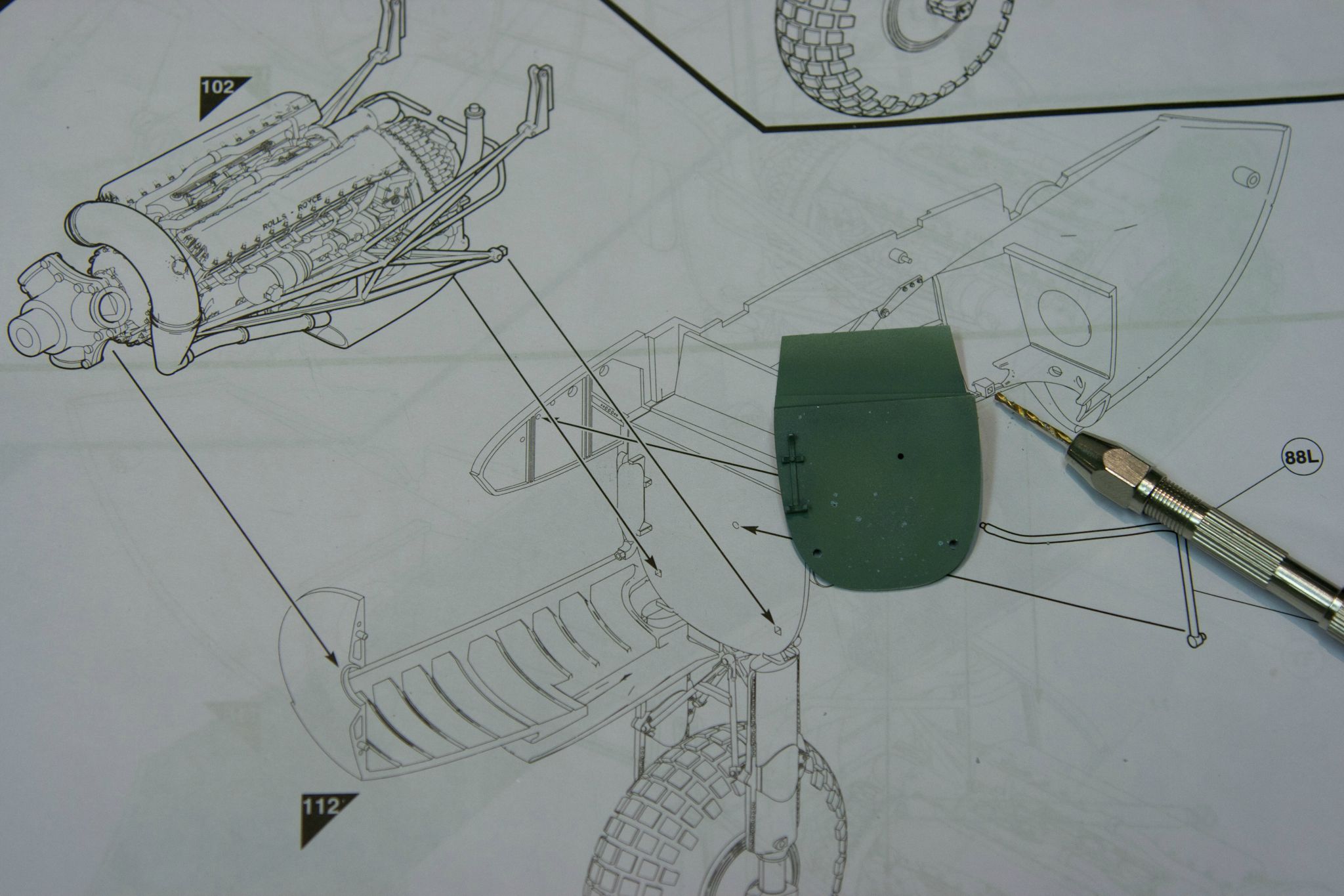
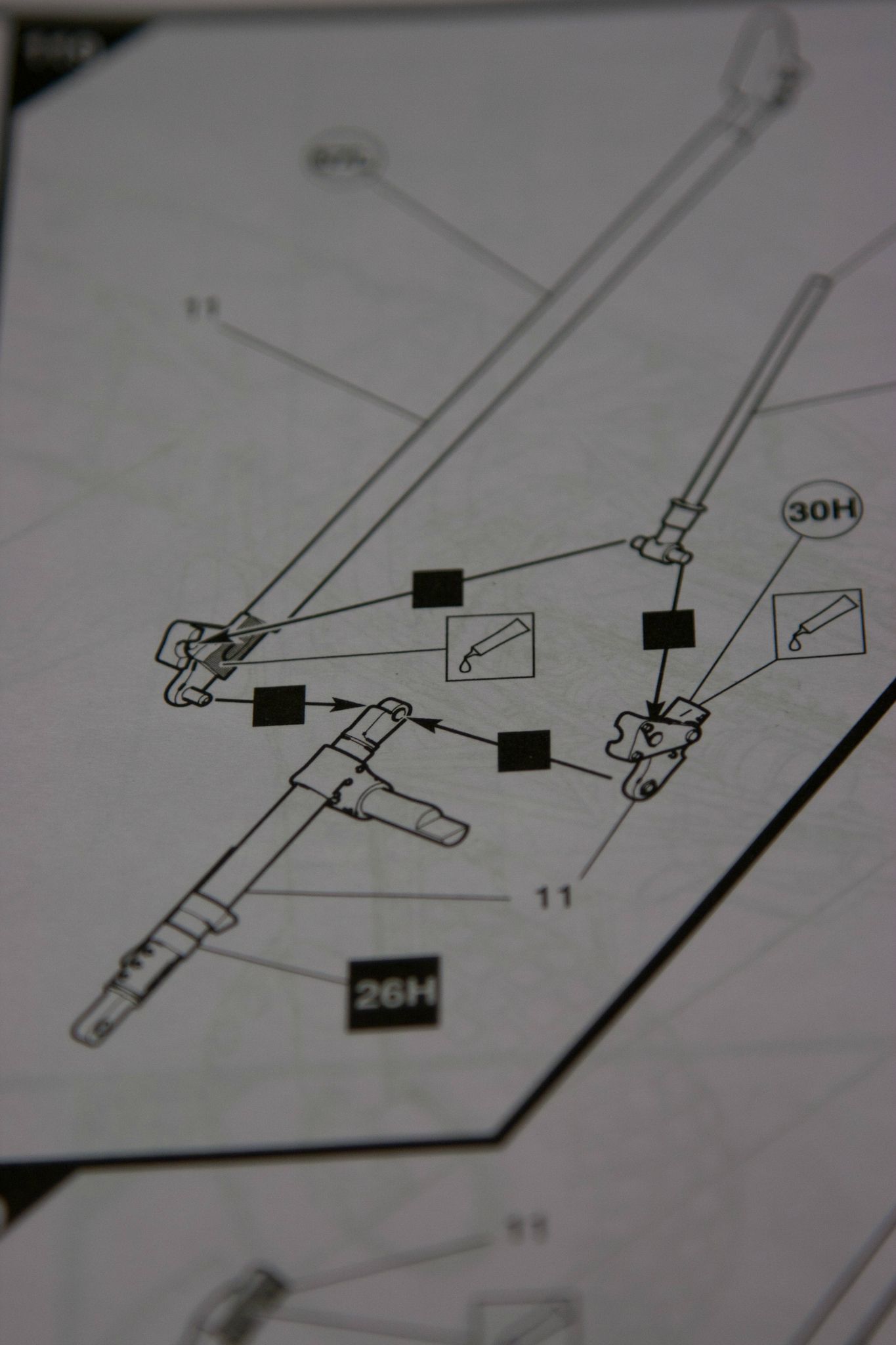
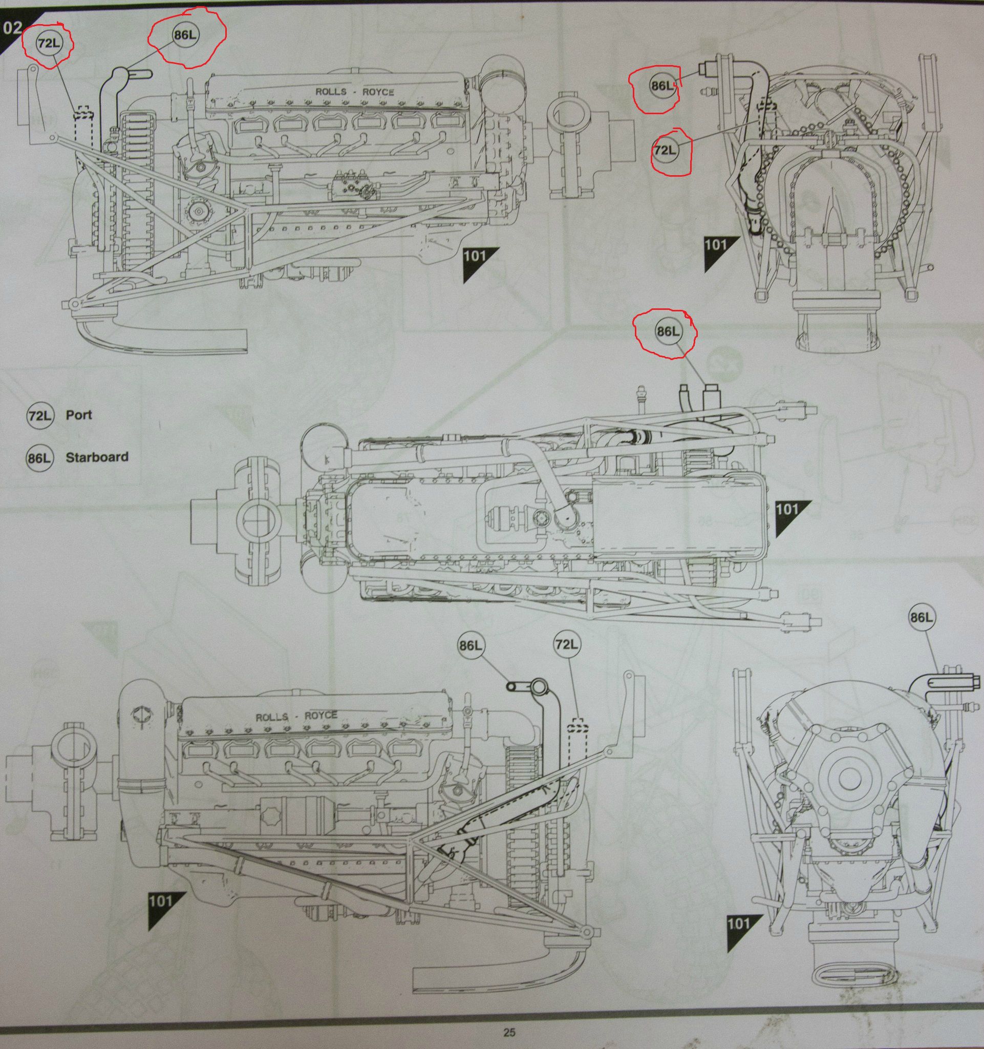
This is the offending step - I've mentioned it before, it seems like a courtesy four view drawing; which it is. But amidst all the regular construction steps it gets a little lost. I stared at it a few times before I noticed it's indicating the installation of two new parts which I've circled. The problem stems from how differently this step is illustrated and the fact that Airfix uses almost the same symbol for paint, decals and parts and they tend to get lost in the ink (can someone explain to me why the hell they had to make a huge instruction manual for a huge kit? I have NOWHERE to put this stuff!
Fake Edit; these seem far more obvious now that I've circled them.
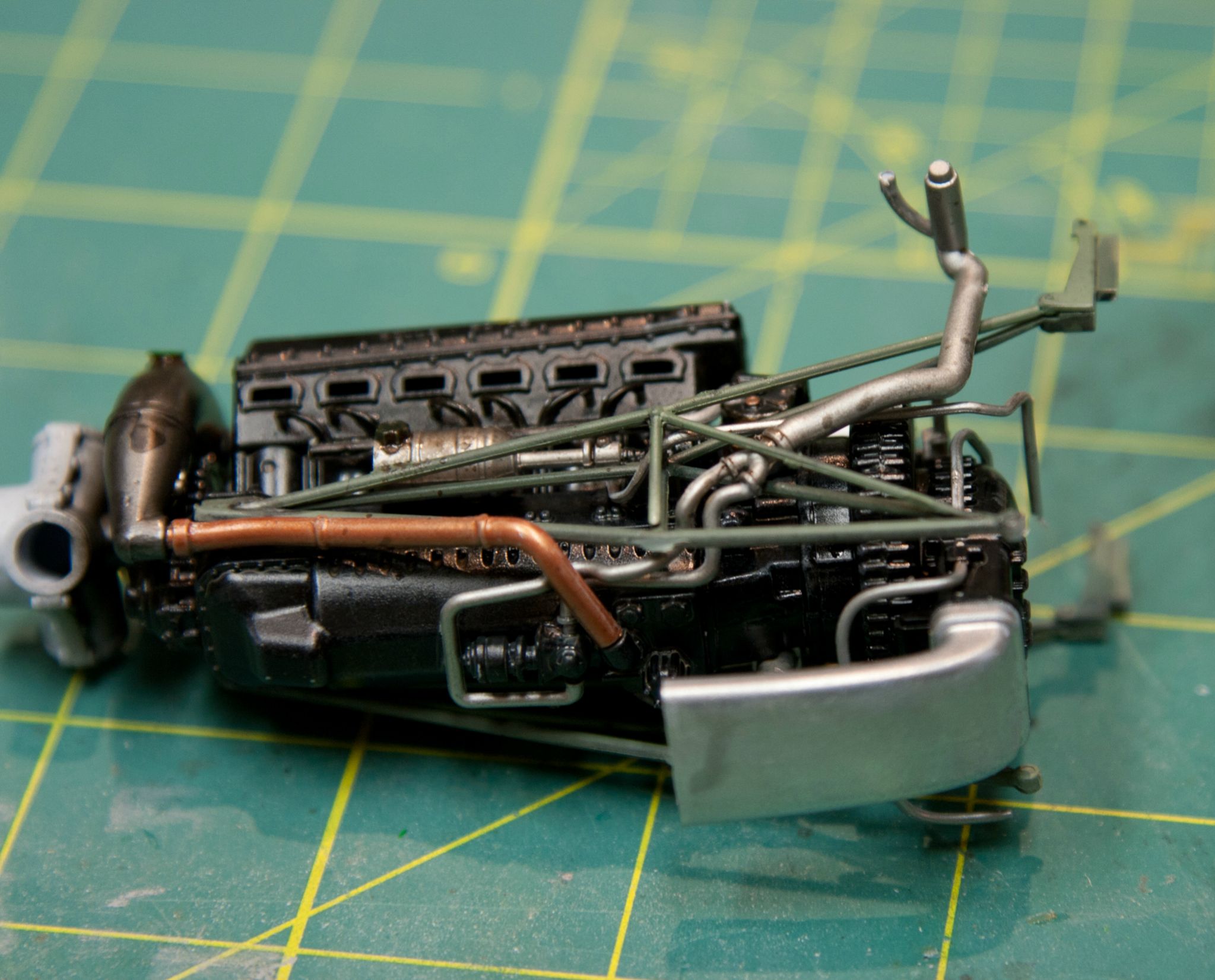
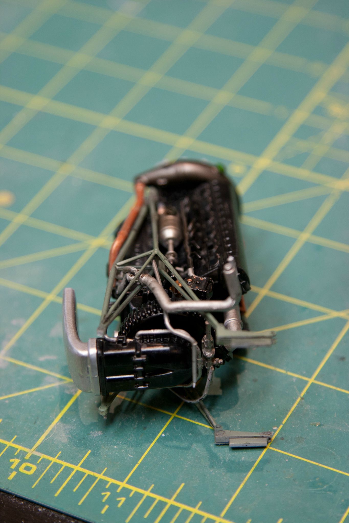
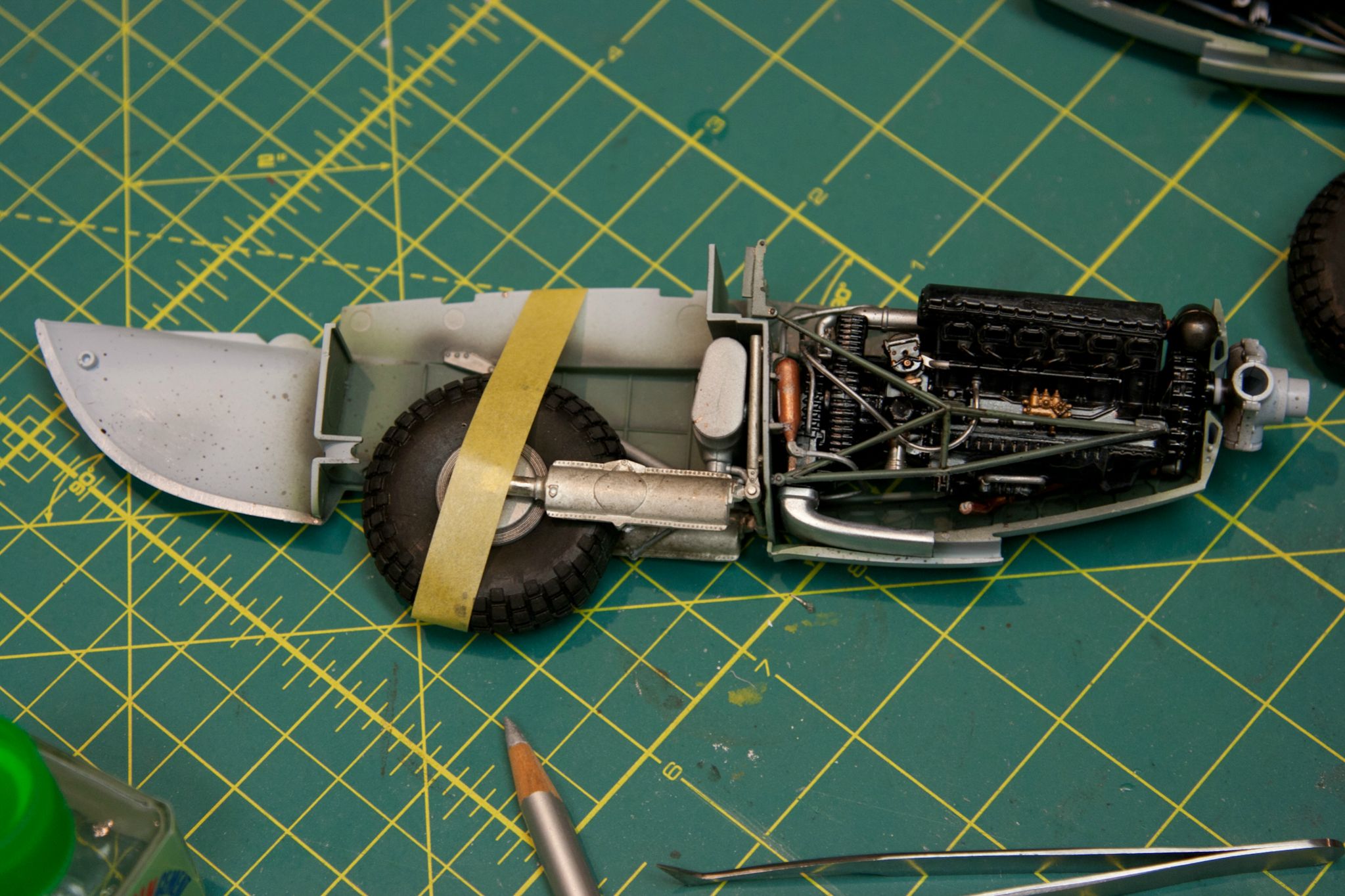
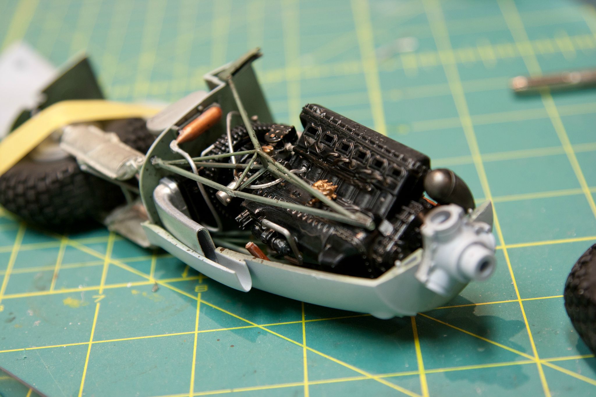
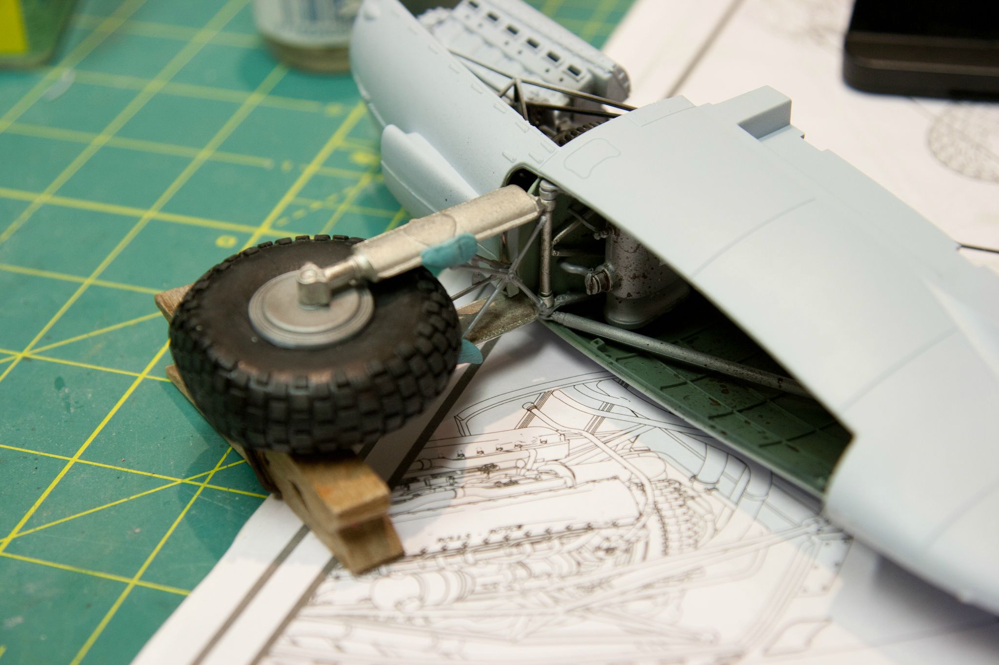
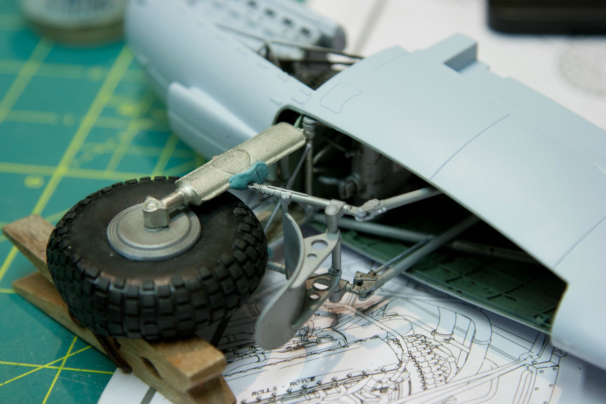
Here's images from an earlier update. I've put one of the main coolant pipes outside the engine bearer when it should have been inside, and I put a small tube that runs through the middle of the engine barer but is supposed to go on the outside of the coolant tube....I'm glad I drew this out in paint for you.
You can see where the coolant tube meets the two smaller coolant lines - they are held in with glue and stick into the pipe only by about 1/16th". They are routed correctly in front of the inside frame and behind the outside frame, but the assembly needs to be inside the upper arm of the bearer (this is all inside the nacelle at this point or I could have corrected it easily had I known at this point)
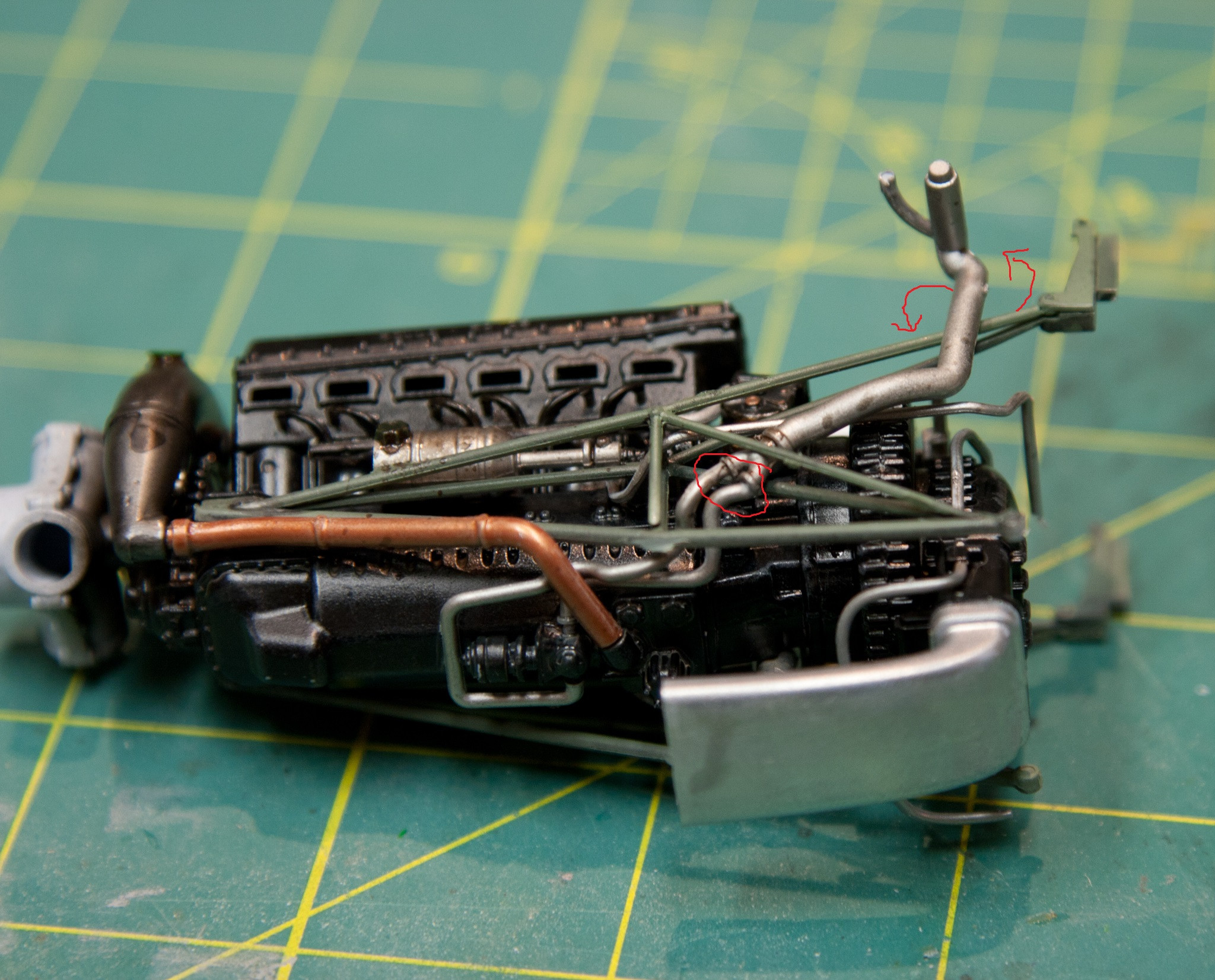
Here's the smaller tubing, it's correctly inside the inner and outer frame, but needs to be outside the coolant pipe. These tubes are smaller than 1/16" and break so easily that you'll want to handle them as little as possible. I can't recommend RB's micro saw set highly enough - I promise that you wont ever get these parts off their sprue without breaking them if you try to use a sprue cutter or number 11 blade.
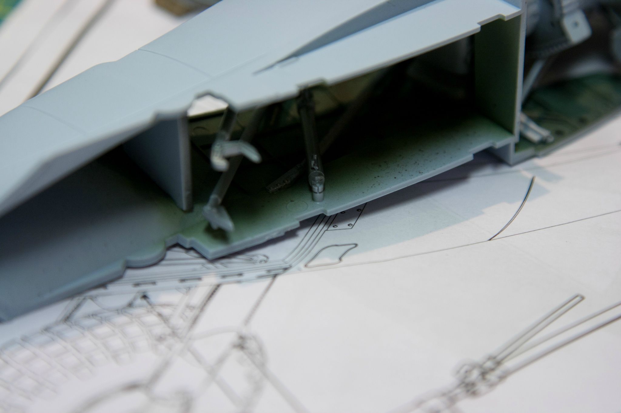
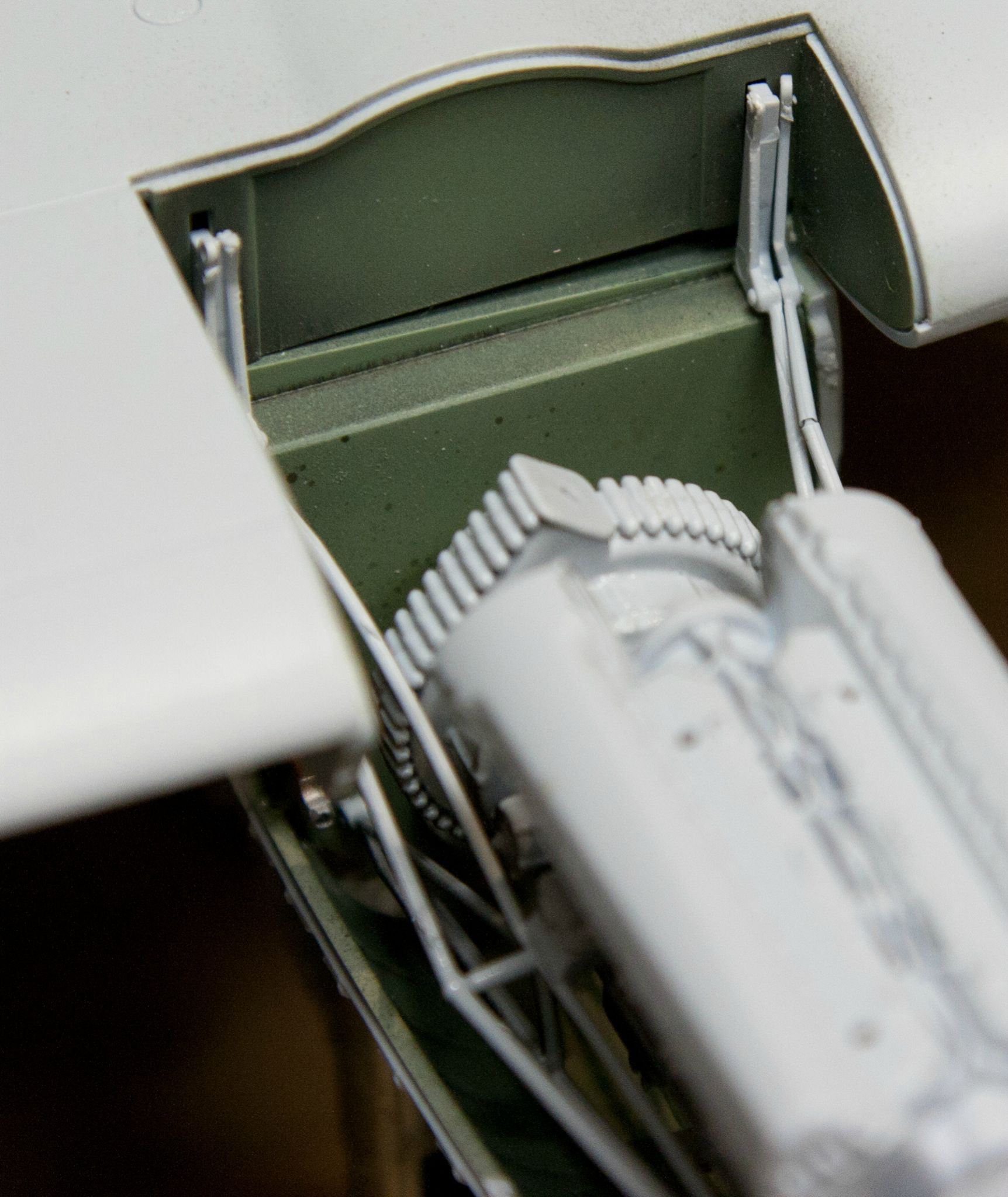
The mounts at the top of the frame sit on this shelf and are slotted into holes in the upper wing - something that isn't made clear in the instructions. Because the assembly is so large (the nacelles) and the engine is being pushed rearward while the bulkhead that the frame slots into slides forward and at this point you're out of hands, almost every single one of these pairs will break on you. They break cleanly though so you can line them up again and friction fit them, touch them with cement and you're good to go. I also found that most of these are too long to begin with, pushing the upper mounts further back than the bulkhead which exacerbates the problem. Melting them back into one piece with contact cement takes care of both problems
You can see the arm has snapped, and you can see how both sides are buckling as there isn't enough room - and this side has none of the plumbing in place

Incredibly fragile
So I had two options to correct this problem - as this was the only engine being displayed it had to be done correctly. option 1 was to break off the coolant pipe where it joins the two small hoses and re-route everything. Option two was to saw the upper mounting arms, re route them from above and glue to the severed half in the same manner I managed the broken ones. I decided that option 1 wasn't feasible because fitting those parts was a blue language symphony in the first place with the engine out of the nacelle.
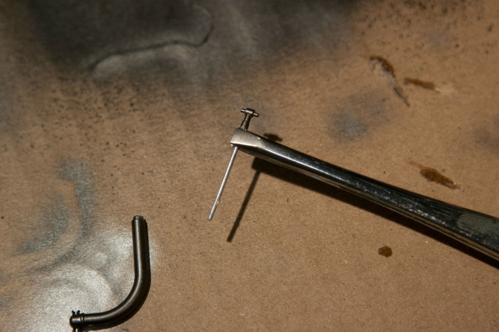
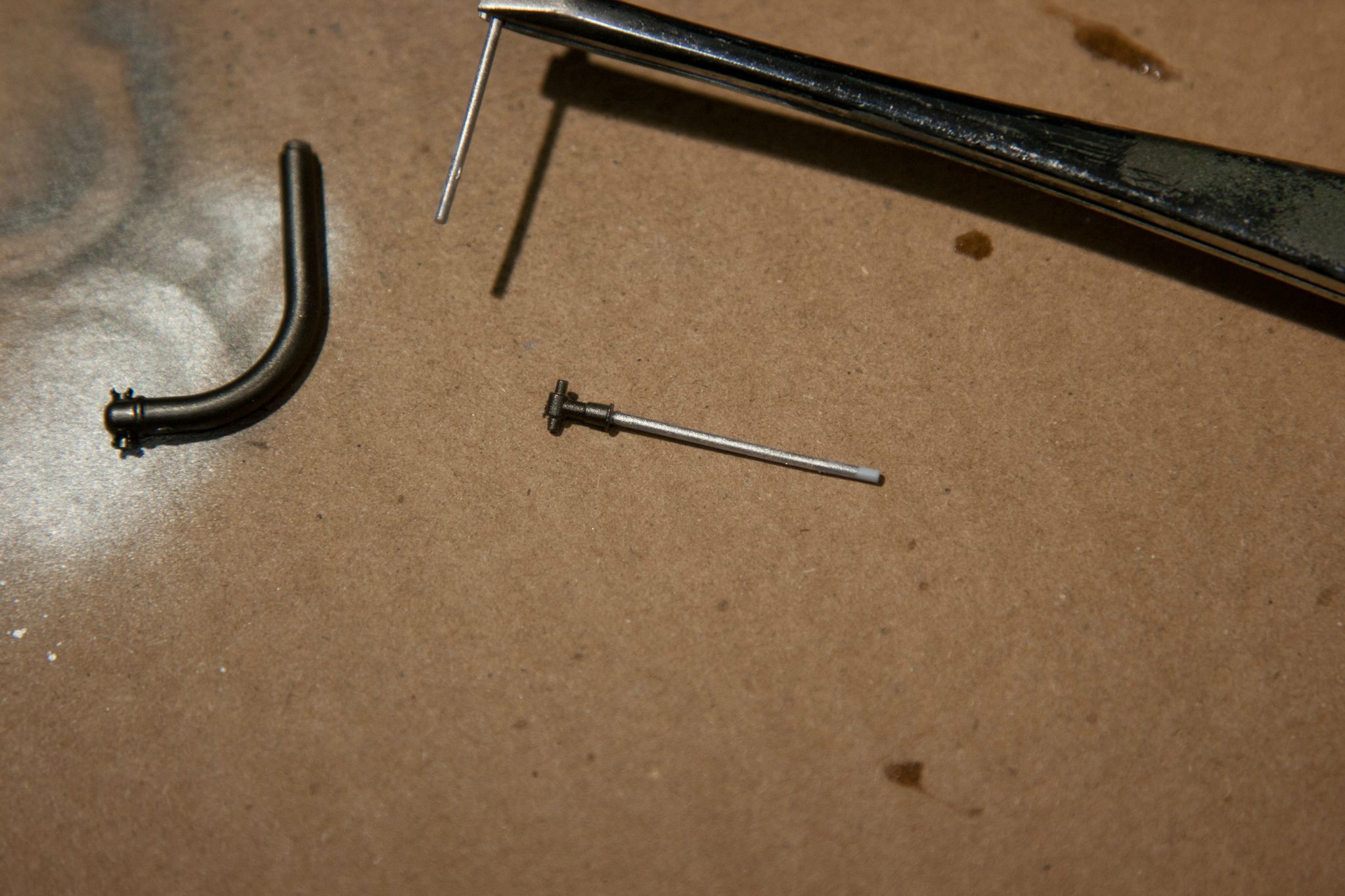
I used one of the amazing mirco saws and made two nice clean cuts leaving a true face on the four ends. It was tricky manouvering a saw between all that plumbing and framework
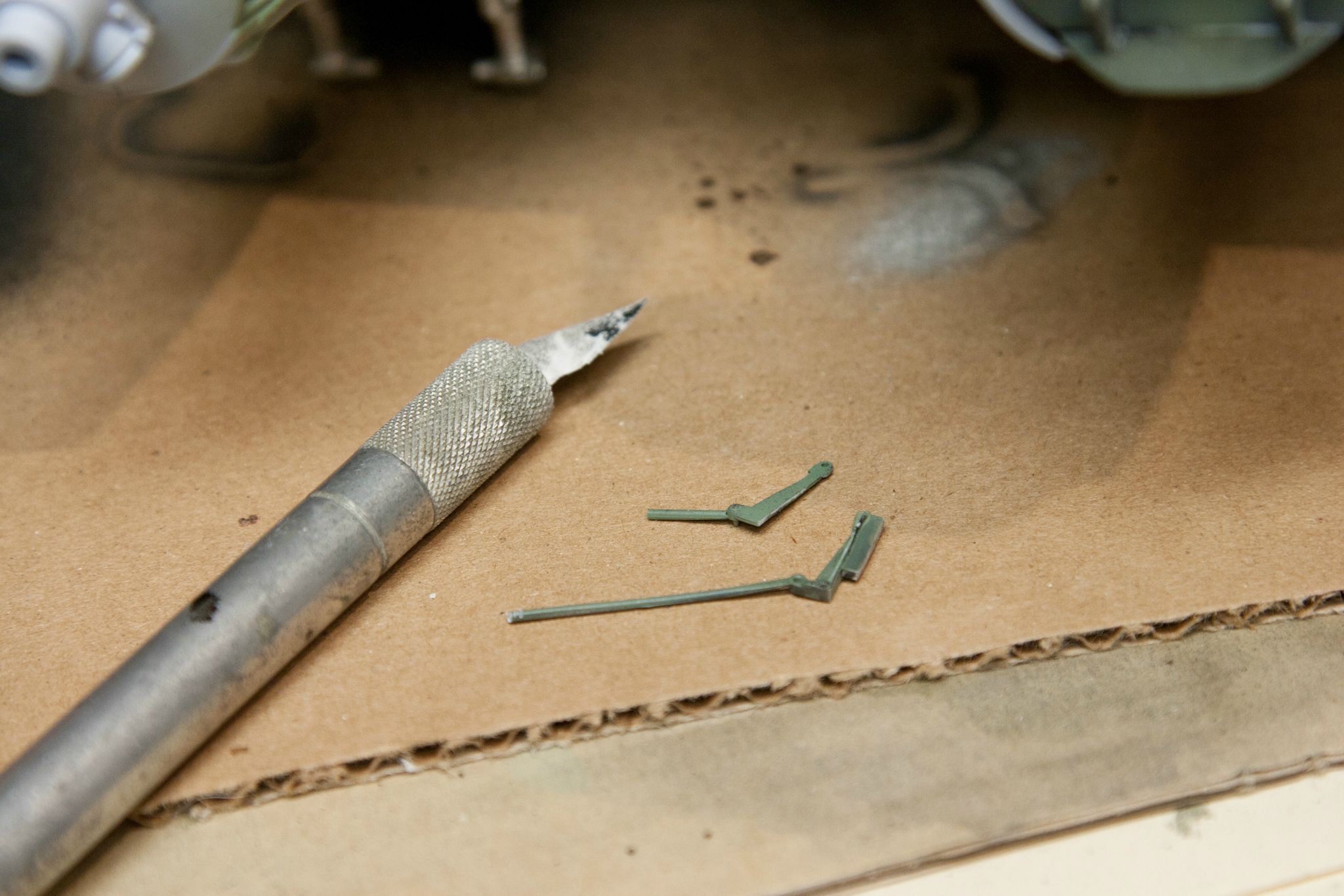
I separated the mount into two pieces. You can see that only one has the block that fits the bulkhead. My plan was to snake the frame down through the plumbing - threading a needle - glue the top to the bulkhead, reattach the other end of that frame and then attach the other part of the upper frame and glue it back to it's other half as well.
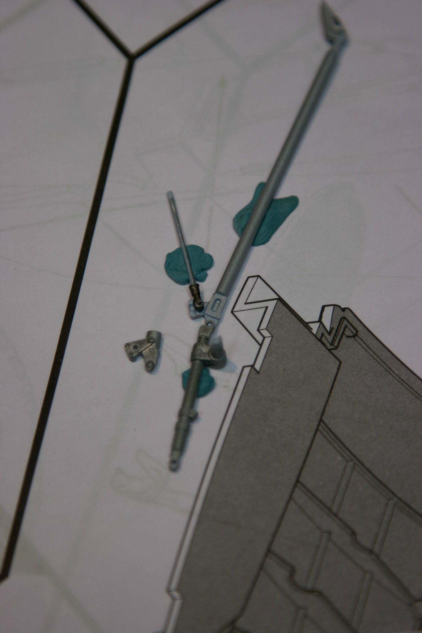
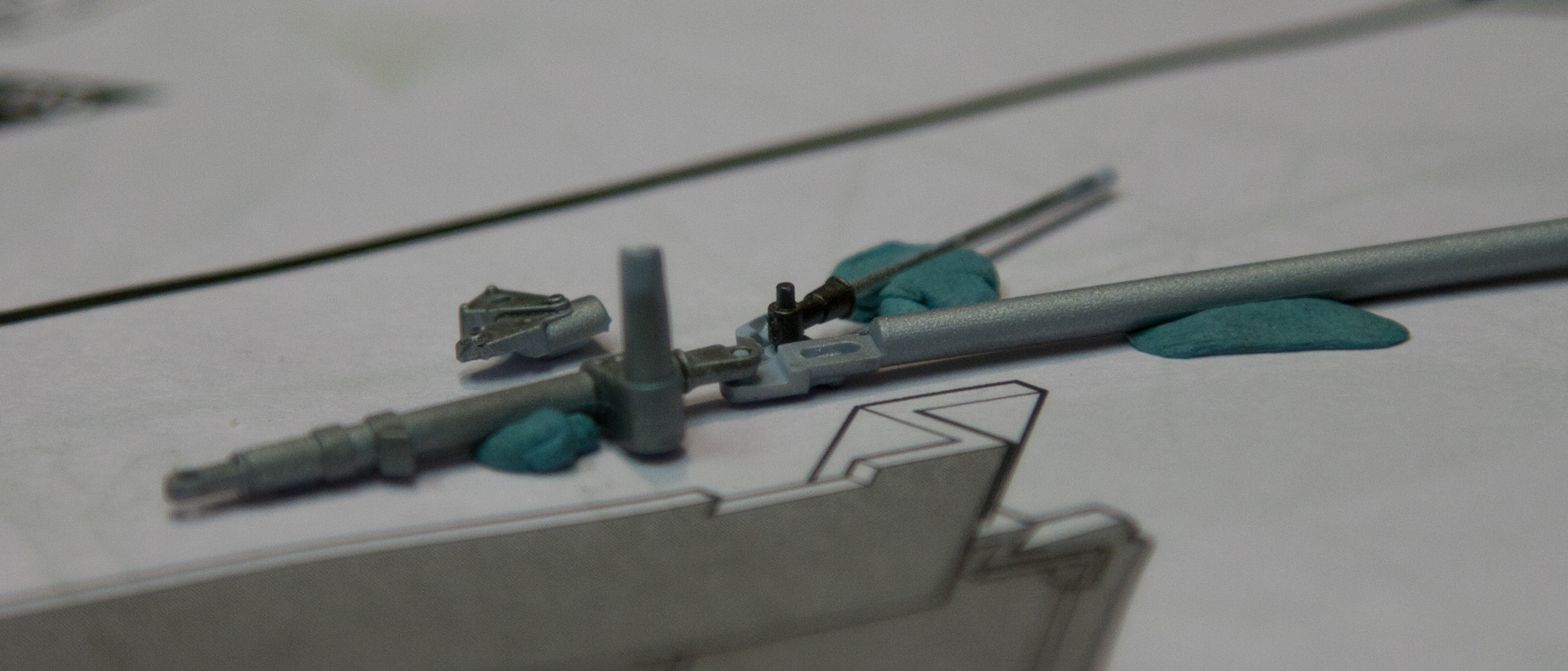
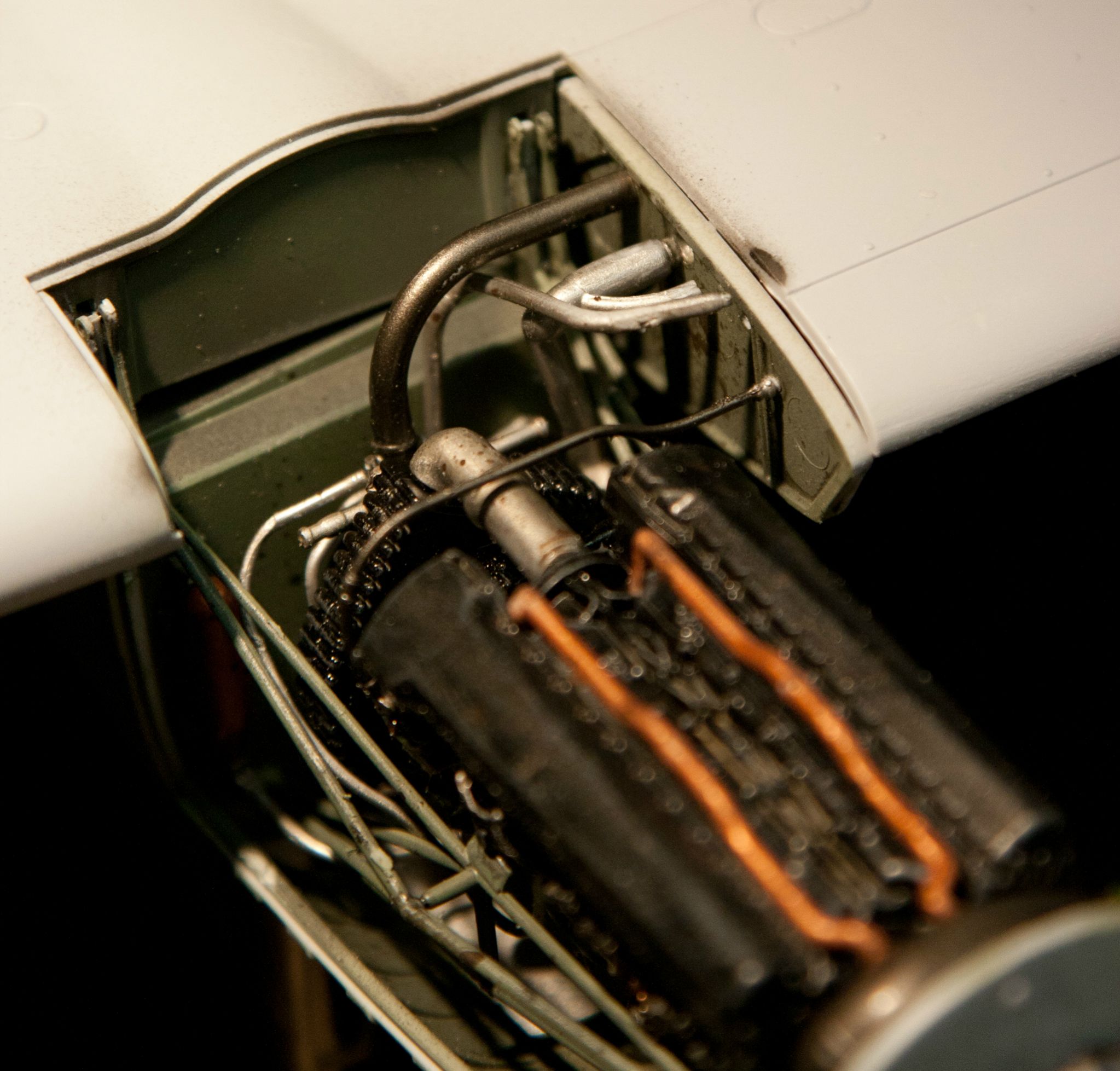
At the top you see the slot, the wide silver pipe far right was the offending one. You can see the two cut ends, one right at the silver coolant pipe and the other down at the bottom of the silver coolant pipe where there's a flange.
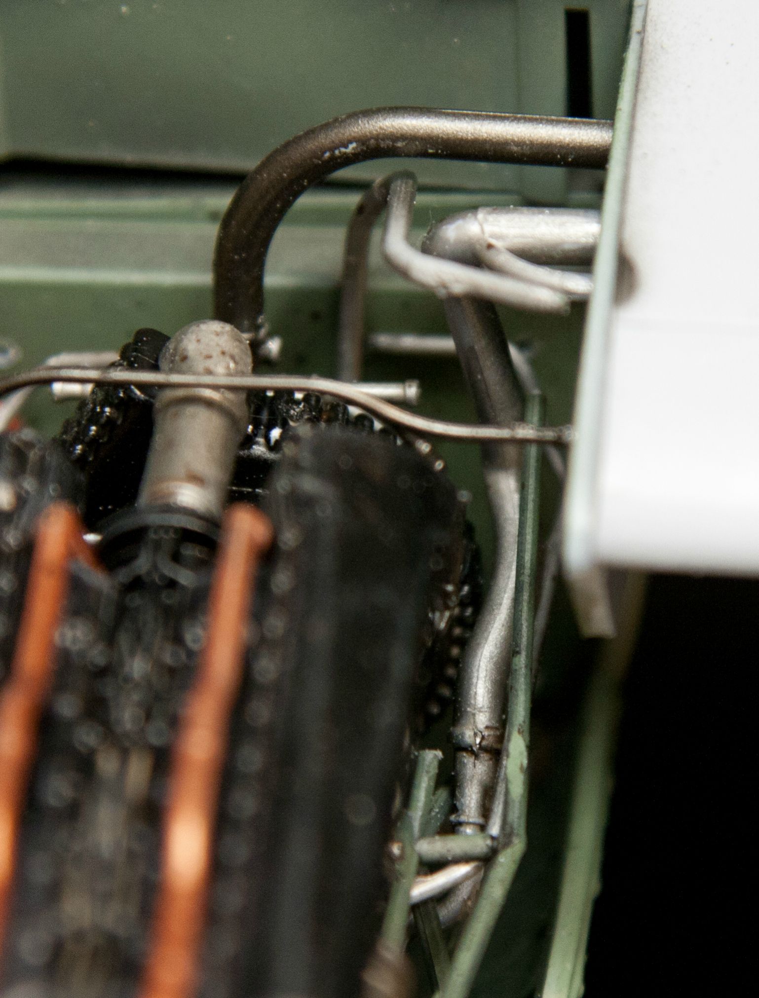
Glued in at the top after being fed down the correct path to approximately where it would mate up with the other side of the cut You get a good idea of how the engine bearers are designed to fit looking at the one on the other side of starboard engine.
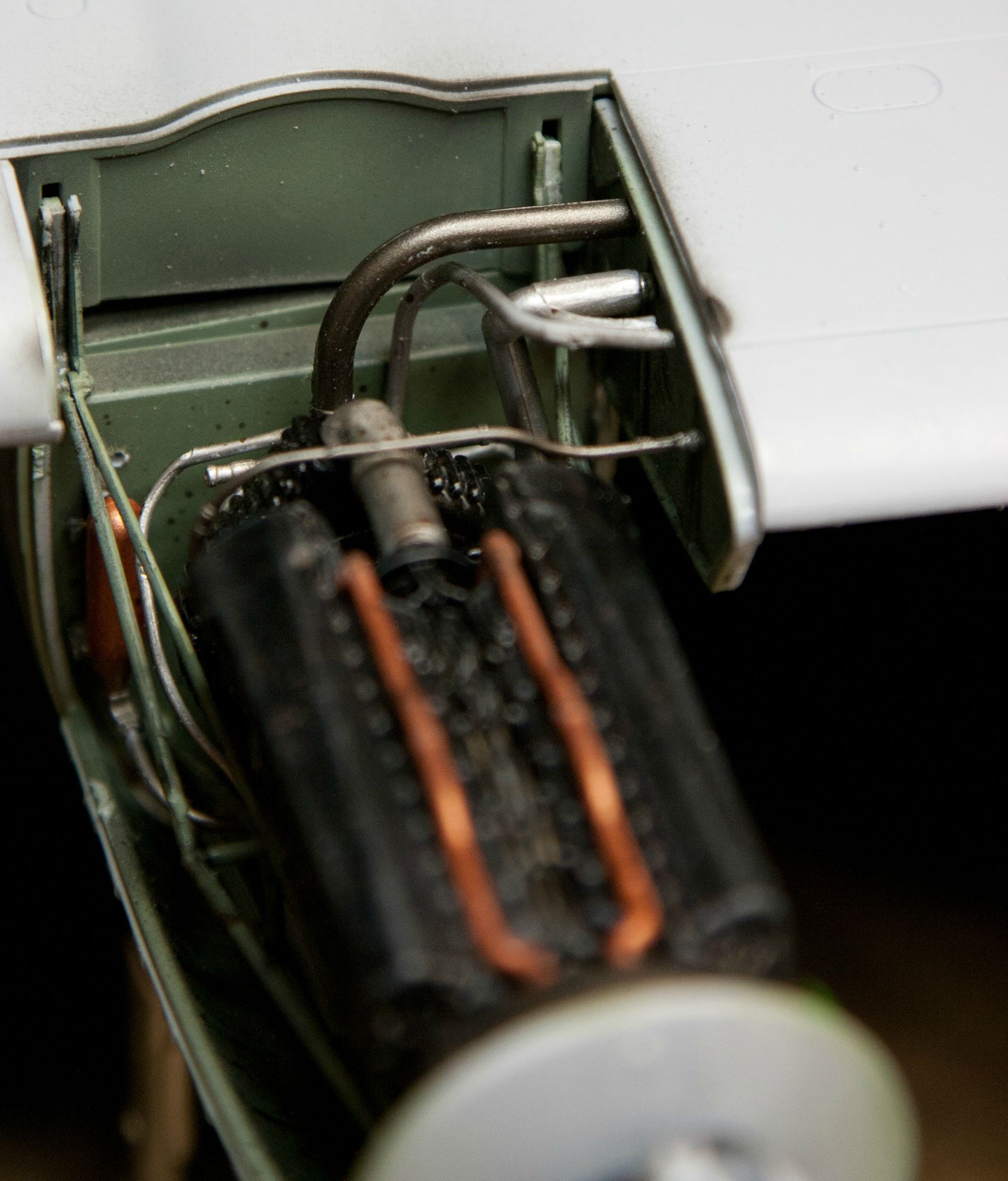
I told you it was almost in line with the frame I cut it off of. needle nose tweezers and the handle an old fine point brush make great tools to place and fiddle until things sit. I had to hold both ends together, put down my brush-prod, find the glue and get it in there without breathing.
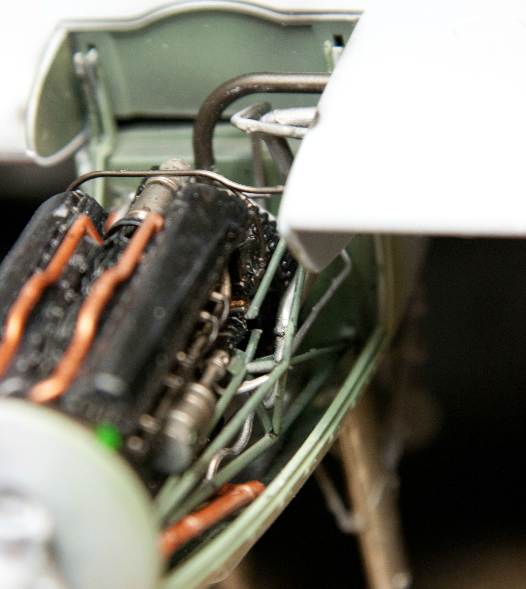
One of two done
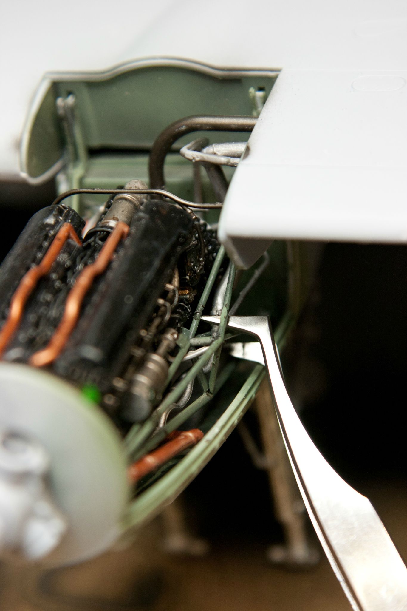
The outside strut fed down through the plumbing to meet up with it's lower half and glued in up top
Sorry I know the lines are small and crude
The green lines are the upper arms now glued back together, light blue is the original offending pipe, darker blue is yet another tube that runs through there, but it's much more obvious how this one fits in. It only runs from the firewall up to that bulkhead.
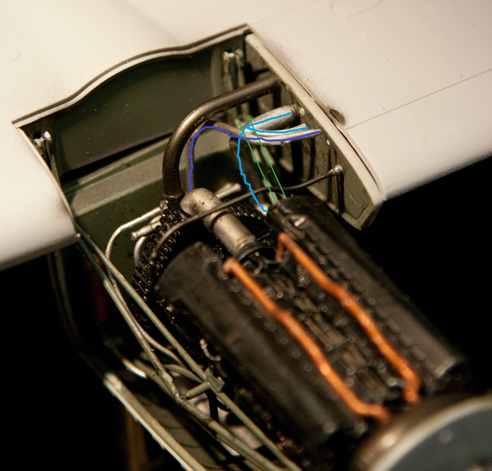
Saved the day. Before I started the green lines curved up inside the thick silver pipe and the mounting block on the end of the frame fell below the curve at the top of the wing, and I couldn't have that.
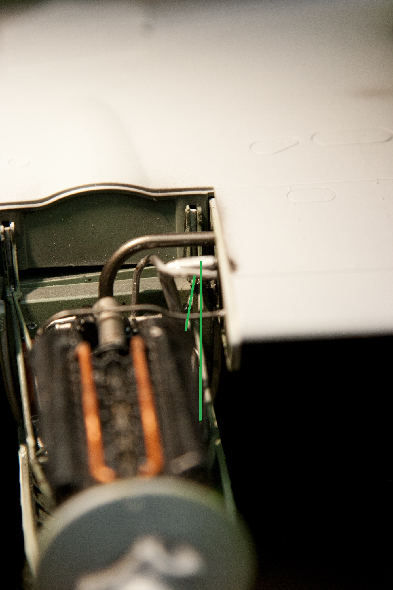
The explanation is much simpler than the problem. I would say go study the instructions and you'll understand, but you wont because they're pretty bad.
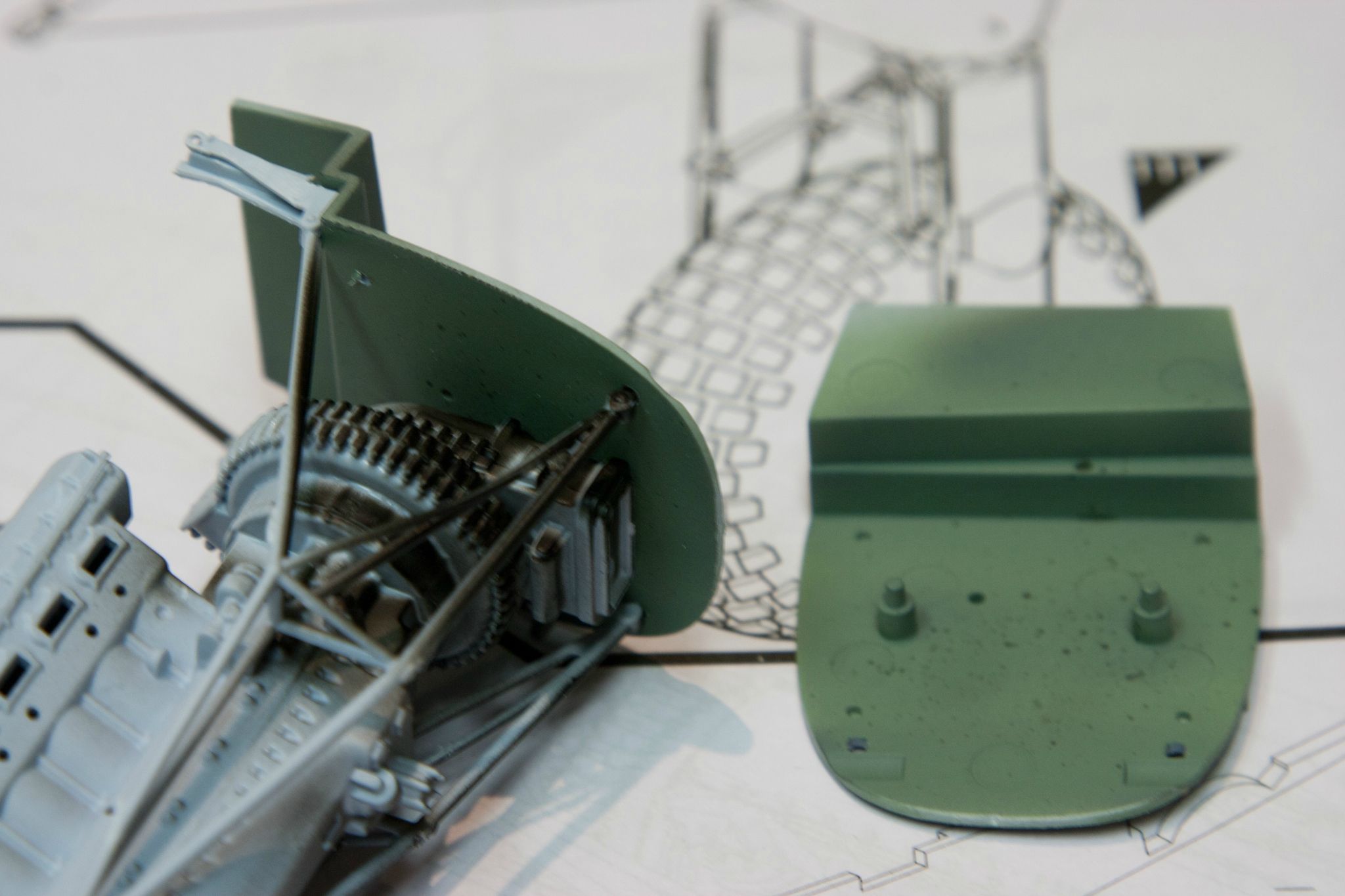
The nacelle which is closed at this point, has the engine in it which is all the way forward, has two mounting pins on the lower arms of the engine cradle which don't fit the firewall, upper arms which just sit above the firewall until you figure out they get inserted to slots in the upper wing AS you attach the nacelles. You have to try and coordinate getting those fragile beams aligned while popping the ungainly nacelle with landing gear in place (but not very secure)into the upper wing - sandwiching the split flaps in place.
That said if this was an engineless kit, the engineering behind the nacelle/wing/flap fit would be genius and rewarding.
I sincerely hope this helps someone when they go to build their Mossie


