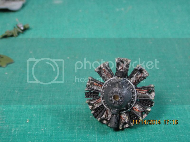
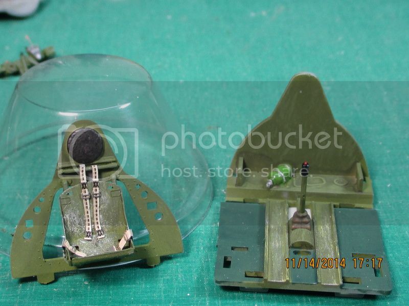
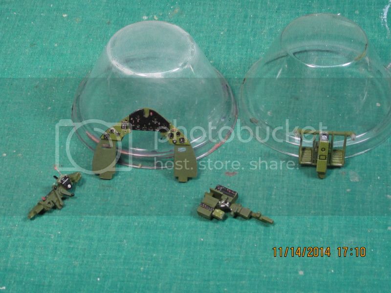
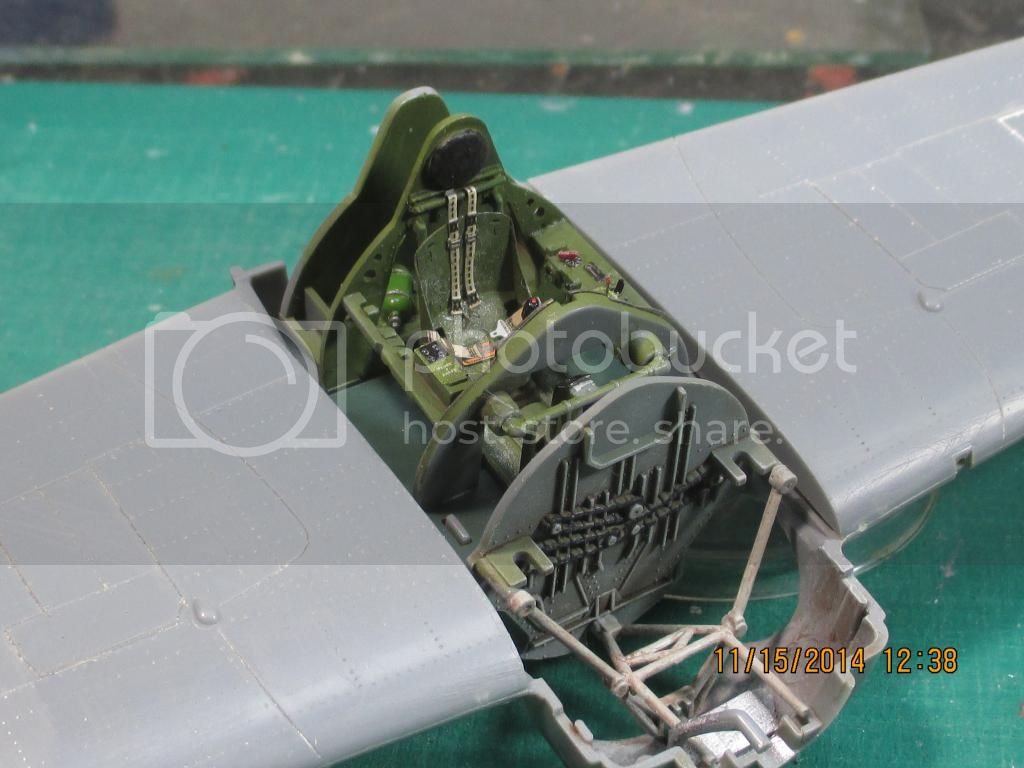
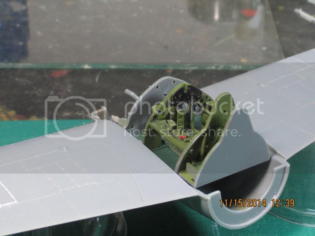
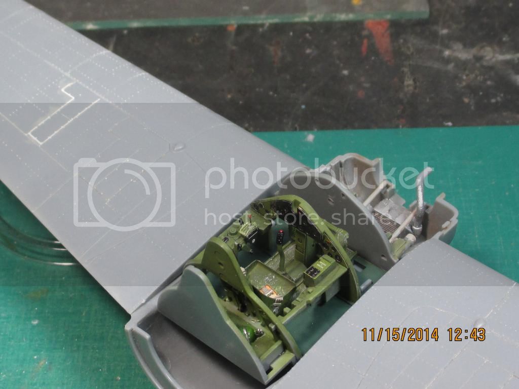
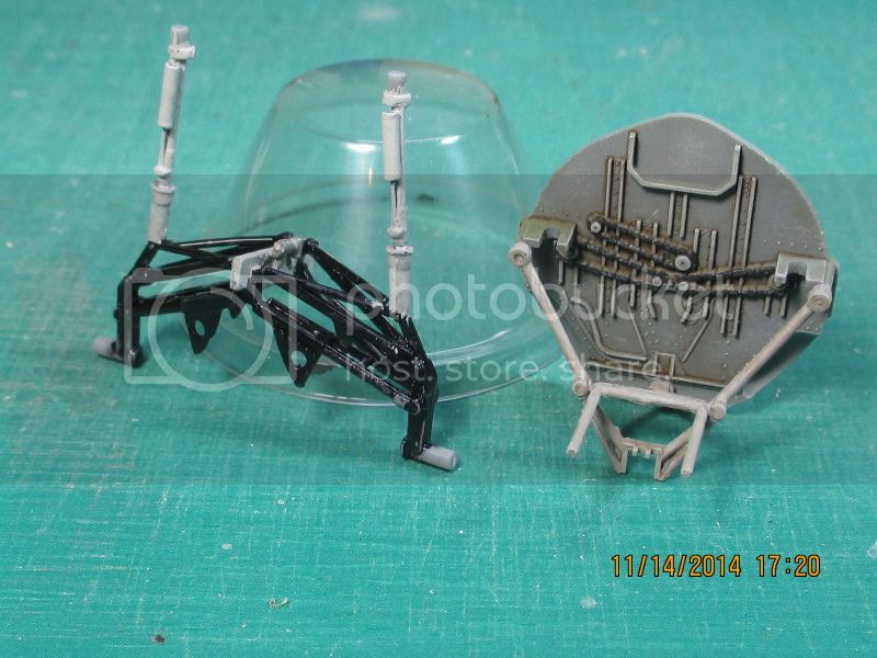
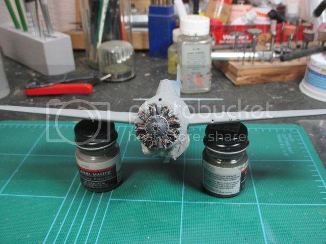
Continuing on with the build, with the cockpit assembly shimmed up to the left upper fuselage half it was time to mate the upper halves to the wing/lower fuselage section. It's a little fussy getting the three sections all in the right place at the right time, but not bad. I think it helps having the cockpit-wheelwell details in the wing section secured and centered as opposed to trying to secure one side and then mate the other, or worse yet, trying to trap misc. parts between two sides. The wing root join in this kit is excellent, even the join with the resin inserts looks good. I ran a strip of masking tape from wingtip to wingtip over the fuselage to keep everything snug and let it dry.
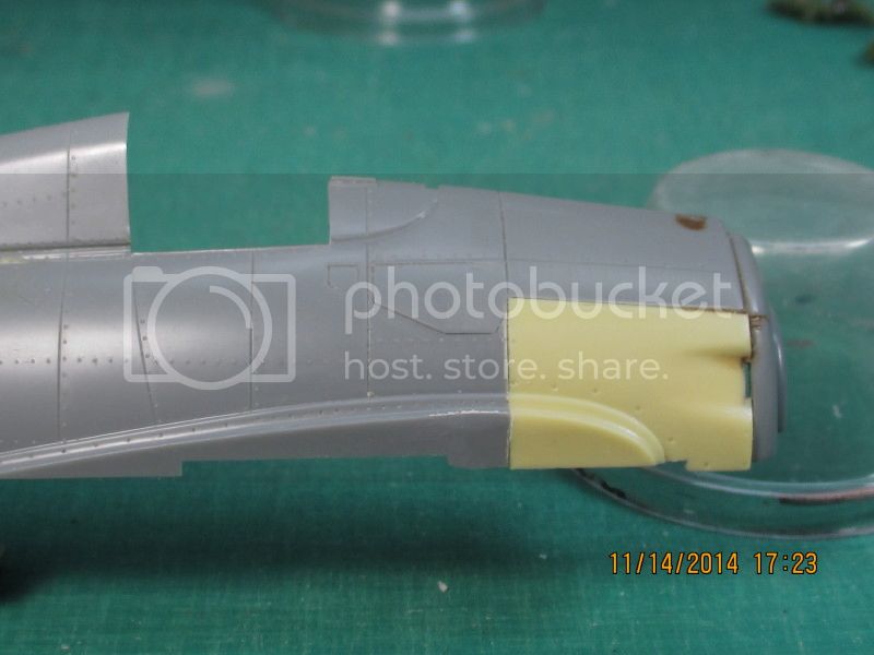
There was a slight gap on the underside where the wing section met the fuselage halves and a slight step just forward of the wing leading edges where the resin inserts met the lower wing section but nothing of import.
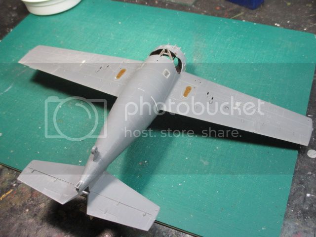
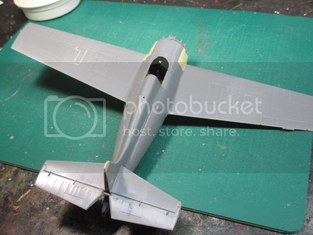
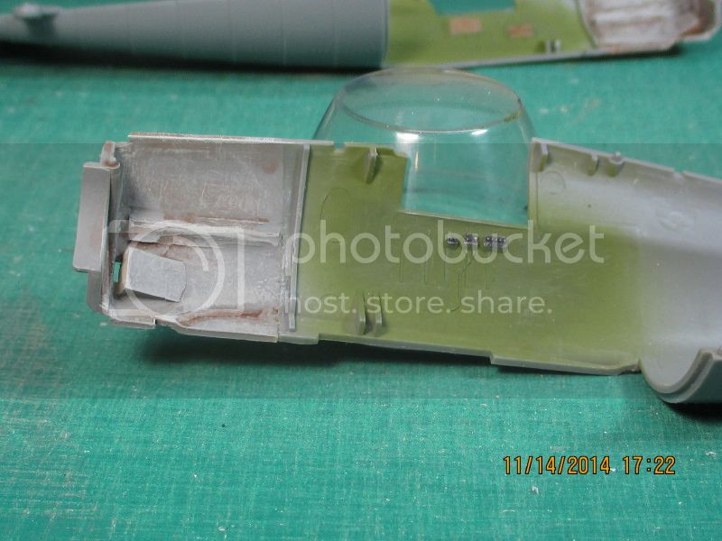
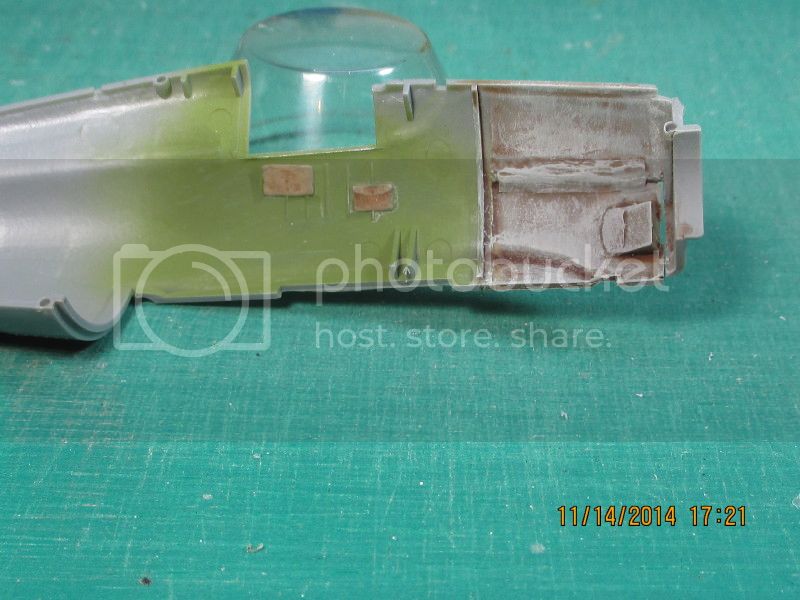
The white arcs in the photo are the fill in the gap between the fuselage sections, as you can see nothing significant. The only downside on this, and it's only a player if your looking for it, is I opted to not rescribe that particular panel line. I used Squadron putty to do my fill because it's easy to sand, flip side is it also chips out easy. I figured my scribing chip the putty out and I'd have to do it all again, best to leave well enough alone. The brownish ovals are the original F4F oil cooler locations which are depressions that require fill since they were removed on the FM-2/ The white rectangles and lines are the outer .50 cal. ejection ports and panel lines. To save weight and boost performance the outer .50's were removed from each wing. Same with the white lines on the top of the wing, fill and sand smooth. I rescribed the major panel lines on the top and bottom of the wings, but still a little detail is lost, a lot of rivets disappeared. With a ponce wheel and say, a major immobilizing injury I might replace those rivets, but not this week. In conjunction with the addition of the cockpit floor, the underside windows were deleted on the FM-2. The kit windows were installed as fillers blended in and sanded smooth.
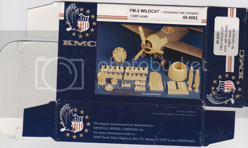
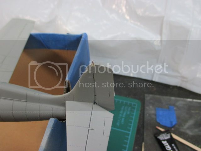
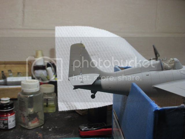
A couple of shots of the resin parts before priming. The cowling and engine are just stuck on at this point (for appearances) but the rudder and tail extension are fixed. The KMC FM-2 rudder and extended tail are one resin piece and meant to be attached as one piece. The resin tail extension is a little thinner than the existing tail top on the Tamiya kit so a little blending is in order here. I did not like the way the combo rudder/tail piece fit on the existing vertical stabilizer, and if feasible I like to offset the rudder on my models slightly to give a more candid appearance. In this case I felt it would help the fit as well. The new problem is, you've got a very small piece that only butt joins to the adjacent piece (can you say fragile!). The extension piece is so thin that drilling a hole for a reinforcing wire would have it's own set of hazards. In the end I opted for the butt join and hoped for the best.


