Air Campaigns
Want to start or join a group build? This is where to start.
Want to start or join a group build? This is where to start.
Hosted by Frederick Boucher, Michael Satin
OFFICIAL: Training / Two-Seater Campaign

Jessie_C


Joined: September 03, 2009
KitMaker: 6,965 posts
AeroScale: 6,247 posts

Posted: Saturday, March 21, 2015 - 09:50 AM UTC
That's an amazing amount of work on that ancient and hollowed kit. The designer would never recognise it 

scribbles101

Joined: May 25, 2013
KitMaker: 137 posts
AeroScale: 103 posts
Posted: Monday, March 23, 2015 - 08:01 PM UTC
Quoted Text
That's an amazing amount of work on that ancient and hollowed kit. The designer would never recognise it
I second that! That AT 11 is barely recognisable from what came out of the box, its a vast improvement! Nice work

Any way, the only after market addition I will be making to the Vampire has arrived
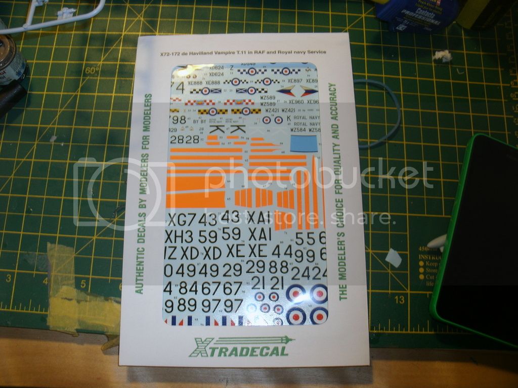
So, I am about ready to make a start on the final leg of the T.11 build!
I have to say that although these decals look very nicely printed, I am dubious about the markings I will be using, they should be red, not fluorescent orange, this is a very similar scheme to the one I want to use

as you can see, there is a marked difference in the colour of the markings ... I will see how I go to start with, but may end up having to do a lot of masking so I can paint the stripes on in red...
Cheers, Simon
RedDuster

Joined: March 01, 2010
KitMaker: 7,078 posts
AeroScale: 118 posts

Posted: Saturday, March 28, 2015 - 03:59 AM UTC
RedDuster

Joined: March 01, 2010
KitMaker: 7,078 posts
AeroScale: 118 posts

Posted: Sunday, March 29, 2015 - 12:22 AM UTC
Posted: Tuesday, March 31, 2015 - 02:40 PM UTC
Posted: Tuesday, March 31, 2015 - 08:43 PM UTC
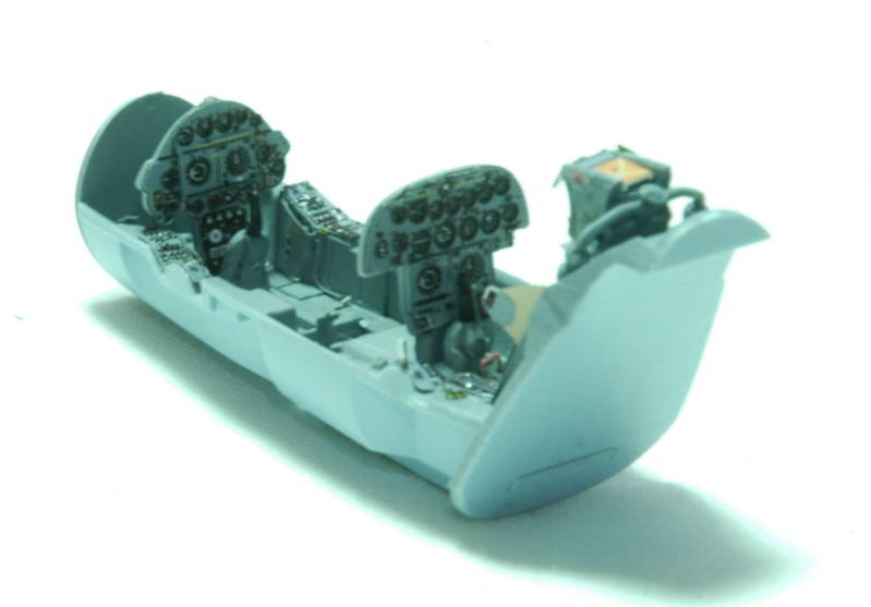
6 hours later the cockpit is done.
Andy
Andy

RedDuster

Joined: March 01, 2010
KitMaker: 7,078 posts
AeroScale: 118 posts

Posted: Friday, April 03, 2015 - 02:16 AM UTC
On with the Tiggy.
The struts are moulded are in pairs, not connected by hevy bars that sit I grooves in the wins, but by a frame designed to be cut away once glued in place.

the links cut away, the struts painted and the upper wing fitted. It worked, aided by the positive fit of the cabane struts to the fuselage this was the easiest fit of upper wing ever!.

rigging next!
Si
The struts are moulded are in pairs, not connected by hevy bars that sit I grooves in the wins, but by a frame designed to be cut away once glued in place.

the links cut away, the struts painted and the upper wing fitted. It worked, aided by the positive fit of the cabane struts to the fuselage this was the easiest fit of upper wing ever!.

rigging next!
Si
Thearmorer

Joined: June 17, 2014
KitMaker: 121 posts
AeroScale: 118 posts

Posted: Friday, April 03, 2015 - 07:11 AM UTC
The AT-11 build continues, although somewhat in fits and starts. Having roughed out the fuselage and gotten the major structural members in place, I've not got to furnish it. My main inspiration for the aft compartment is this shot:

This is the same photo that was used earlier in this build, I tired to enlarge it to show a little more detail, we'll see how it comes out. Looking at the original copy the oxygen bottles are clearly visible in the foreground and the trainee appears to be sitting on a jump seat that probably folds back up against the rear bulkhead behind him. The oxygen bottles weren't a problem, Quickboost does a great little set meant for a 1/72nd scale B-24 that includes these bottles as well as the larger yellow type mounted on large bomber aircraft. On those I made an "L" shaped bracket to hold four of them so I wouldn't have to place each in position separately. That worked pretty well except that even though I measured the bottles with a vernier caliper, I just measured the diameter of the bottle, not the little rings around each. I cut the bracket to fit the bottles, not the bottles plus rings. Hence things are a little crowded in there. These rings aren't 1/10th of mm in height off the bottle, but you pack them in, they sneak up on you. The jump seat is a fabrication of masking tape and 24 gauge craft wire bent on a pair of flat nose pliers.

A square frame was made to hold the tape seat with the excess wire bent back and trimmed to fit. Since this seat looks to be back in the corner, I figured I'd get away with only one leg which is towards the open crew door. The flight deck seats are from the Hobbycraft C-45 kit which are quite a bit better than the ones that are in the AT-11.

The seat on the left is the AT-11 version. The little pegs go into holes on the flight deck floor and it just squats there. The seat on the right is how the instructions with the C-45 want you to install it, sit it on the floor and glue the sides to it. A bit crude perhaps but at least better than ole Peg Leg there. Since I'm being a bit anal on this build anyway, I opted to sand the bottom of the seat down some to get it off the floor, and look a little more to scale, and less like a barka-lounger. The center seat is where I ended up, plus some stiffeners on the back made from stretched sprue. On this type of aircraft, flight crew usually wore the backpack type parachute as opposed to the seatpack type normally seen on fighter type aircraft. With this in mind I opted to make seat cushions out of 20 thousandths sheet styrene and painted leather with a little lighter highlighting to give the seat a little color. The seats themselves were painted interior green with a light dryburshing of Floquil platinum mist to show wear. I thought about painting the seats bronze green, since there are several period photos showing seats that color, but since I went with a bronze green color for the plywood floors, I figured the seats would just blend into the floor at this scale, so interior green it is.


This is the current state of affairs of the interior. The seats are just stuck in-place to test for fit at this stage. I'm presently on hold in the interior as I am AWP (awaiting parts) as we used to say, until my lap-belts arrive. My original plan was to use tape for belts with extremely fiddly little bits of wire for buckles etc. until Airfix by way of Eduard saved me much effort. Eduard put out several PE sheets to go along with Airfix's new C-47 kit, one of which is lap-belts for the troop seats in the cargo compartment. The AT-11's were not known for their aerobatic prowess in flight, they just went up and bored holes in the sky while the trainee's dropped iron in the dirt and went home. With this in mind I suspect everybody just had a lap-belt, which is the way I'm going to play it. I figure one set of lap-belts will suffice for this and several future projects. This is the current state of affairs:


I need the seatbelts on before I can install the seats, which in turn have to be in prior to securing the flight deck bulkhead and floor, which has to be in place to get the instrument panel and console lined up so I can get on with this:


This is the same photo that was used earlier in this build, I tired to enlarge it to show a little more detail, we'll see how it comes out. Looking at the original copy the oxygen bottles are clearly visible in the foreground and the trainee appears to be sitting on a jump seat that probably folds back up against the rear bulkhead behind him. The oxygen bottles weren't a problem, Quickboost does a great little set meant for a 1/72nd scale B-24 that includes these bottles as well as the larger yellow type mounted on large bomber aircraft. On those I made an "L" shaped bracket to hold four of them so I wouldn't have to place each in position separately. That worked pretty well except that even though I measured the bottles with a vernier caliper, I just measured the diameter of the bottle, not the little rings around each. I cut the bracket to fit the bottles, not the bottles plus rings. Hence things are a little crowded in there. These rings aren't 1/10th of mm in height off the bottle, but you pack them in, they sneak up on you. The jump seat is a fabrication of masking tape and 24 gauge craft wire bent on a pair of flat nose pliers.

A square frame was made to hold the tape seat with the excess wire bent back and trimmed to fit. Since this seat looks to be back in the corner, I figured I'd get away with only one leg which is towards the open crew door. The flight deck seats are from the Hobbycraft C-45 kit which are quite a bit better than the ones that are in the AT-11.

The seat on the left is the AT-11 version. The little pegs go into holes on the flight deck floor and it just squats there. The seat on the right is how the instructions with the C-45 want you to install it, sit it on the floor and glue the sides to it. A bit crude perhaps but at least better than ole Peg Leg there. Since I'm being a bit anal on this build anyway, I opted to sand the bottom of the seat down some to get it off the floor, and look a little more to scale, and less like a barka-lounger. The center seat is where I ended up, plus some stiffeners on the back made from stretched sprue. On this type of aircraft, flight crew usually wore the backpack type parachute as opposed to the seatpack type normally seen on fighter type aircraft. With this in mind I opted to make seat cushions out of 20 thousandths sheet styrene and painted leather with a little lighter highlighting to give the seat a little color. The seats themselves were painted interior green with a light dryburshing of Floquil platinum mist to show wear. I thought about painting the seats bronze green, since there are several period photos showing seats that color, but since I went with a bronze green color for the plywood floors, I figured the seats would just blend into the floor at this scale, so interior green it is.


This is the current state of affairs of the interior. The seats are just stuck in-place to test for fit at this stage. I'm presently on hold in the interior as I am AWP (awaiting parts) as we used to say, until my lap-belts arrive. My original plan was to use tape for belts with extremely fiddly little bits of wire for buckles etc. until Airfix by way of Eduard saved me much effort. Eduard put out several PE sheets to go along with Airfix's new C-47 kit, one of which is lap-belts for the troop seats in the cargo compartment. The AT-11's were not known for their aerobatic prowess in flight, they just went up and bored holes in the sky while the trainee's dropped iron in the dirt and went home. With this in mind I suspect everybody just had a lap-belt, which is the way I'm going to play it. I figure one set of lap-belts will suffice for this and several future projects. This is the current state of affairs:


I need the seatbelts on before I can install the seats, which in turn have to be in prior to securing the flight deck bulkhead and floor, which has to be in place to get the instrument panel and console lined up so I can get on with this:

RedDuster

Joined: March 01, 2010
KitMaker: 7,078 posts
AeroScale: 118 posts

Posted: Sunday, April 05, 2015 - 01:40 AM UTC
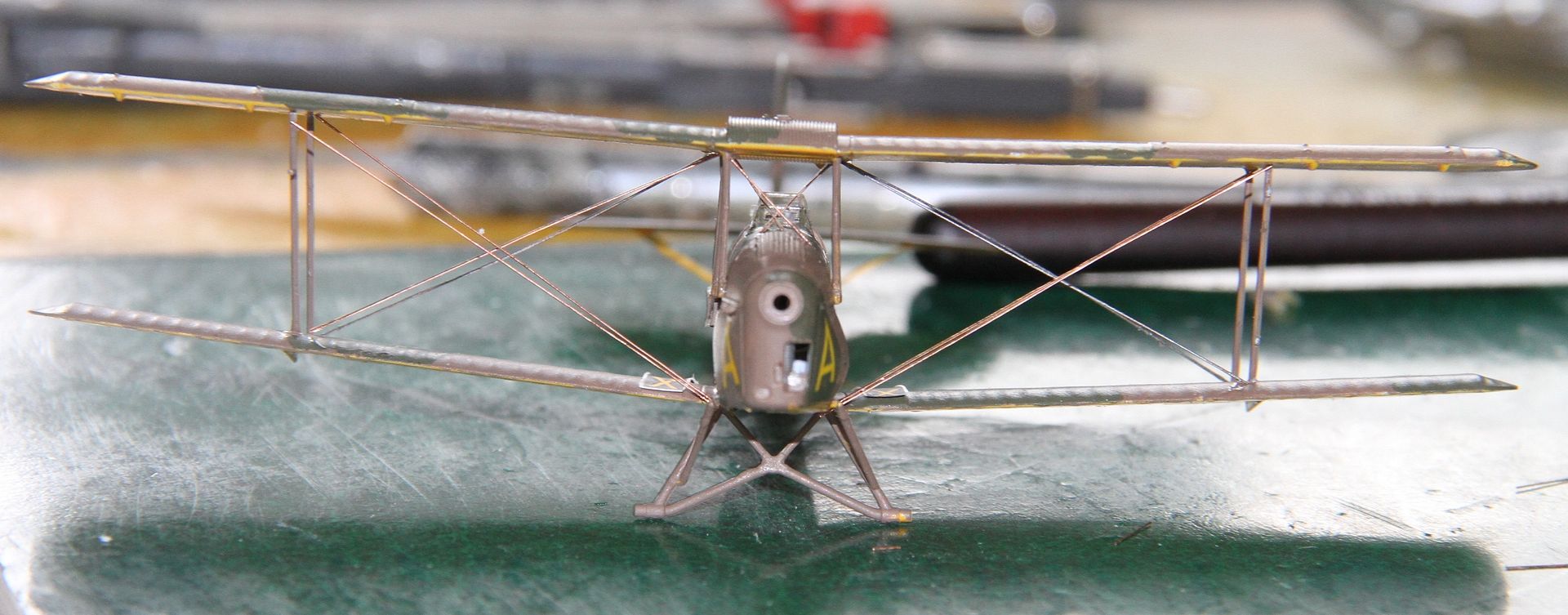
On with the tricky bit, the rigging.
Airfix provide an excellent step by step rigging guide in the instructions.

Steps A and B completed.

Step C, unusually on the Tiger Moth, both landing wires come from the after cabane strut.

Step D, the flying wires.
 ,
,
And finally for today step E, the bracing between the interplane struts,
More soon.
Si
Airfix provide an excellent step by step rigging guide in the instructions.

Steps A and B completed.

Step C, unusually on the Tiger Moth, both landing wires come from the after cabane strut.

Step D, the flying wires.
 ,
, And finally for today step E, the bracing between the interplane struts,
More soon.
Si
Posted: Sunday, April 05, 2015 - 03:52 AM UTC
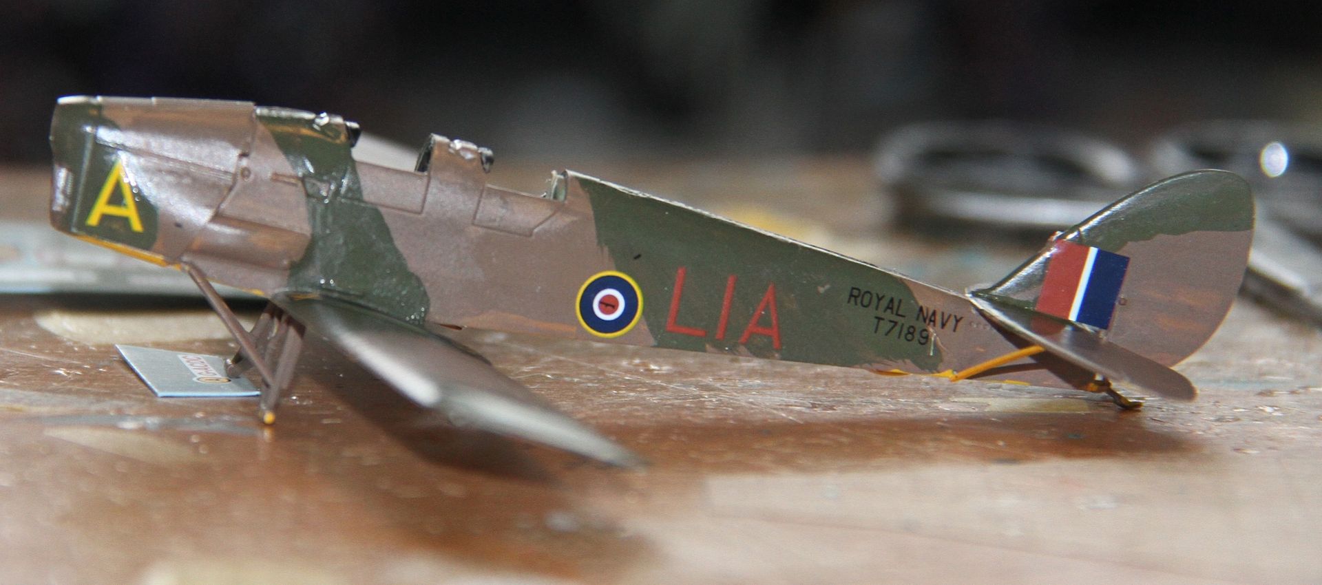
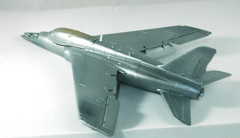
Well the majority of the parts are together, and now concentrating on the paint scheme. The silver has been applied, and the red/orange will go on in the next couple of days.
Andy
Andy

TangoOscarMike

Joined: April 02, 2015
KitMaker: 35 posts
AeroScale: 16 posts
Posted: Sunday, April 05, 2015 - 07:36 AM UTC
RedDuster

Joined: March 01, 2010
KitMaker: 7,078 posts
AeroScale: 118 posts

Posted: Tuesday, April 07, 2015 - 12:13 AM UTC
Stoker

Joined: February 07, 2015
KitMaker: 58 posts
AeroScale: 19 posts

Posted: Tuesday, April 07, 2015 - 05:25 AM UTC
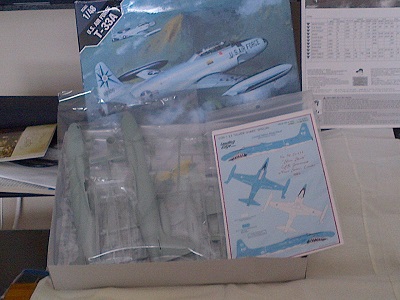
Hi Everybody, I just signed up for this campaign. I'm planning on building an Academy 1/48 T-33 to represent a Canadian CT-133 "Silver Shark" Special using decals from Leading Edge.

RedDuster

Joined: March 01, 2010
KitMaker: 7,078 posts
AeroScale: 118 posts

Posted: Sunday, April 12, 2015 - 01:13 AM UTC

jimb

Joined: August 25, 2006
KitMaker: 2,539 posts
AeroScale: 231 posts

Posted: Sunday, April 12, 2015 - 11:15 PM UTC
Nice job on the Tiger Moth, Simon. What did you use for rigging?
Jim
Jim
Thearmorer

Joined: June 17, 2014
KitMaker: 121 posts
AeroScale: 118 posts

Posted: Tuesday, April 14, 2015 - 10:01 AM UTC
My AT-11 upgrade lumbers on, while my interior work was on hold for seatbelts I decided to attack the wings. Since the C-45 engine cowlings were more to my liking and the C-45 wing was altogether closer to what I was after, that's the route I'm going. The main landing gear mounts further forward in the gear well as shown in this shot:

The AT-11 wing put the gear strut back quite a bit in the gear well. The down side of the C-45 gear well is that it's just a big hole in the bottom of the wing. My solution to that was to cut the boxed in wheel wells on the AT-11 wings and glue them into the openings in the C-45 wings. They fit surprisingly well with a little serious sand paper work, and some notching to accept my home made exhaust stacks. These probably aren't particularly accurate, but since I wasn't able to find any good shots of the AT-11 or C-45 wheel wells they'll have to do. In any event they're better than a big hole in the bottom of the wing.

These are the inserts from the AT-11 and show where they wanted to place the main gear on that kit. I just filled the holes with styrene rod and sanded it off. The holes in the outer wing are for the landing lights (more on that in a bit).

The interior was painted Tamiya metallic gray, which is my current favorite for oxidized aluminum, and a couple of sections of craft wire tubing to busy things up a bit. The hole in the depression in the forward wheel well area is where the C-45 main gears attach, not very convincing but at least they're in the right place.

This is with the engines and nacelles in place. The engines were meant to go with these nacelles but the fit was poor, the engines were too small for the cowling (especially since I did some surgery to add the cowl flaps) and getting them in and aligned required epoxy and some strong anglo-saxon incantations. Under the right wing is a landing light, one of the AT-11 clear parts. For a fuselage window these things are useless, but for a light with a bulb in it they aren't bad. The AT-11 kit had only one light and under the right wing as shown. The C-45 kit had two smaller holes under each wing, which I in a profound state of blissful ignorance filled with a piece of styrene rod and sanded smooth. Since the AT-11 kit hasn't been right about much of anything else that's on the real thing, why I decided to follow their lead on this particular feature completely baffles me at this point. Naturally about two days later (after the wings are sealed tighter than a drum), while searching through some tomes of ancient knowledge on a completely different quest I stumble across a great picture of an AT-11 coming in for a landing. There in all their glory are "TWO" landing lights just like the C-45 kit wanted me to do. I'll write it off to a terrible taxi-ing accident (I might even put a scab patch on that side).

This is with the engines in-place and the leading edge air intakes eye-balled for location since neither kit represents them in any way. The oval holes should be a little more rectangular, but I didn't want to take a chance and overdo it. I still have some sanding to do on the cowlings, you'll note on this picture that there is no definitive forward cowl ring on the real aircraft.

The cowl rings on the C-45 kit are quite noticeable and will have to be blended in. This shot also shows to good effect that goofy shaped astro-dome for the navigator trainees. Next back inside.

The AT-11 wing put the gear strut back quite a bit in the gear well. The down side of the C-45 gear well is that it's just a big hole in the bottom of the wing. My solution to that was to cut the boxed in wheel wells on the AT-11 wings and glue them into the openings in the C-45 wings. They fit surprisingly well with a little serious sand paper work, and some notching to accept my home made exhaust stacks. These probably aren't particularly accurate, but since I wasn't able to find any good shots of the AT-11 or C-45 wheel wells they'll have to do. In any event they're better than a big hole in the bottom of the wing.

These are the inserts from the AT-11 and show where they wanted to place the main gear on that kit. I just filled the holes with styrene rod and sanded it off. The holes in the outer wing are for the landing lights (more on that in a bit).

The interior was painted Tamiya metallic gray, which is my current favorite for oxidized aluminum, and a couple of sections of craft wire tubing to busy things up a bit. The hole in the depression in the forward wheel well area is where the C-45 main gears attach, not very convincing but at least they're in the right place.

This is with the engines and nacelles in place. The engines were meant to go with these nacelles but the fit was poor, the engines were too small for the cowling (especially since I did some surgery to add the cowl flaps) and getting them in and aligned required epoxy and some strong anglo-saxon incantations. Under the right wing is a landing light, one of the AT-11 clear parts. For a fuselage window these things are useless, but for a light with a bulb in it they aren't bad. The AT-11 kit had only one light and under the right wing as shown. The C-45 kit had two smaller holes under each wing, which I in a profound state of blissful ignorance filled with a piece of styrene rod and sanded smooth. Since the AT-11 kit hasn't been right about much of anything else that's on the real thing, why I decided to follow their lead on this particular feature completely baffles me at this point. Naturally about two days later (after the wings are sealed tighter than a drum), while searching through some tomes of ancient knowledge on a completely different quest I stumble across a great picture of an AT-11 coming in for a landing. There in all their glory are "TWO" landing lights just like the C-45 kit wanted me to do. I'll write it off to a terrible taxi-ing accident (I might even put a scab patch on that side).

This is with the engines in-place and the leading edge air intakes eye-balled for location since neither kit represents them in any way. The oval holes should be a little more rectangular, but I didn't want to take a chance and overdo it. I still have some sanding to do on the cowlings, you'll note on this picture that there is no definitive forward cowl ring on the real aircraft.

The cowl rings on the C-45 kit are quite noticeable and will have to be blended in. This shot also shows to good effect that goofy shaped astro-dome for the navigator trainees. Next back inside.
Thearmorer

Joined: June 17, 2014
KitMaker: 121 posts
AeroScale: 118 posts

Posted: Wednesday, April 15, 2015 - 01:03 AM UTC
Well the resupply chopper finally made it up here to Festung Millerhaus and included in the haul was the long awaited Eduard seatbelts. I was greatly relieved to see them up-close and personal, in all the on-line catalog shots on my computer all the Eduard belts seem to have this weird pinkish tan color that doesn't match anything I've ever seen on a real aircraft, belonging to anybody. Thankfully the actual color is an off white color which is quite workable in 1/72nd scale.

That is a millimeter scale in the background to give some indication of the size of these things. I'm really glad I decided to go this route and not try to manufacture my own. I've found through much trial and error (emphasis on error) that when working with these sub-atomic size details that one has to secure at least one part being worked on to a stationary object. What I've done here is tape the leather pad parts to a glass sheet then apply superglue to the belt portion and carefully place belt on pad.
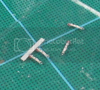
I like the glass sheet because in the event some of the glue finds it's way onto the backing I can still get an x-acto blade under the part an pop it off without having a chunk of my backing material come with it. (does it sound like I'd done that in the past?) That part went fairly smoothly and with a little more fiddling went on the seats in a workable fashion. Naturally the jump seat in the aft section didn't go into the corner as well with the belt attached, but it went with a little persuasion.

And the front.


I knew from previous dry-fitting that the C-45 windscreen part was a little narrow for the AT-11 fuselage in the rear. My first idea was to cut a line from the rear of the windscreen up to the hole for the radio mast which I'd use as a stop-drill and put a styrene wedge in to spread the rear slightly. Upon reflection I figured that was just asking for trouble. The next idea was to purchase the Falcon US canopy set 4 which has a vacuform canopy for the Hobbycraft C-45 which might also be a little small but would be flexible enough to work. The problem with that idea was I'd have to buy a whole set of canopies (for $20+) of which I have no use for the rest in the foreseeable future. I then remembered Franken-Vac! I'd just use the C-45 canopy as a master and home brew a replacement.


It took a couple of tries but I finally got a workable copy.

It's important to note that when trying to vacuform a part you have to keep the part you want elevated above your suction surface, otherwise the plastic will flare out at the bottom of the master and won't snug down. When warping over complex curves there's always a chance of strange folds in the plastic, so have some spare plastic sheets handy.

This is a shot of sort of what the inside should look like:

And this is a couple of shots down the throat of the beast:


And finally a shot in the crew door:

Work progresses on fitting the modified C-45 instrument panel and console into the cockpit, then to attack the nose.

That is a millimeter scale in the background to give some indication of the size of these things. I'm really glad I decided to go this route and not try to manufacture my own. I've found through much trial and error (emphasis on error) that when working with these sub-atomic size details that one has to secure at least one part being worked on to a stationary object. What I've done here is tape the leather pad parts to a glass sheet then apply superglue to the belt portion and carefully place belt on pad.

I like the glass sheet because in the event some of the glue finds it's way onto the backing I can still get an x-acto blade under the part an pop it off without having a chunk of my backing material come with it. (does it sound like I'd done that in the past?) That part went fairly smoothly and with a little more fiddling went on the seats in a workable fashion. Naturally the jump seat in the aft section didn't go into the corner as well with the belt attached, but it went with a little persuasion.

And the front.


I knew from previous dry-fitting that the C-45 windscreen part was a little narrow for the AT-11 fuselage in the rear. My first idea was to cut a line from the rear of the windscreen up to the hole for the radio mast which I'd use as a stop-drill and put a styrene wedge in to spread the rear slightly. Upon reflection I figured that was just asking for trouble. The next idea was to purchase the Falcon US canopy set 4 which has a vacuform canopy for the Hobbycraft C-45 which might also be a little small but would be flexible enough to work. The problem with that idea was I'd have to buy a whole set of canopies (for $20+) of which I have no use for the rest in the foreseeable future. I then remembered Franken-Vac! I'd just use the C-45 canopy as a master and home brew a replacement.


It took a couple of tries but I finally got a workable copy.

It's important to note that when trying to vacuform a part you have to keep the part you want elevated above your suction surface, otherwise the plastic will flare out at the bottom of the master and won't snug down. When warping over complex curves there's always a chance of strange folds in the plastic, so have some spare plastic sheets handy.

This is a shot of sort of what the inside should look like:

And this is a couple of shots down the throat of the beast:


And finally a shot in the crew door:

Work progresses on fitting the modified C-45 instrument panel and console into the cockpit, then to attack the nose.
Thearmorer

Joined: June 17, 2014
KitMaker: 121 posts
AeroScale: 118 posts

Posted: Wednesday, April 15, 2015 - 01:07 AM UTC

WildeSau

Joined: July 01, 2006
KitMaker: 20 posts
AeroScale: 19 posts

Posted: Wednesday, April 15, 2015 - 03:41 AM UTC
I painted the cockpit in silver grey. The norwegian ones were early PT-19 and I hope they hadn't changed the interior color to green then... My plane, my choice, even if it was a bad choice 


SHAKY962

Joined: May 21, 2012
KitMaker: 765 posts
AeroScale: 316 posts

Posted: Wednesday, April 15, 2015 - 04:50 AM UTC
@dmiller: Your work is amazing!!!!
Thearmorer

Joined: June 17, 2014
KitMaker: 121 posts
AeroScale: 118 posts

Posted: Wednesday, April 22, 2015 - 08:18 PM UTC
Jose, thanks for the support, the really amazing aspect of this build is that I've gotten this far based primarily on guesswork and supposition. Now onwards towards the nose (a story of post-nasal drip perhaps?) of this beastie. My fist concern was the fabrication of this rather prominent mount for the Norden bombsight.

My original idea was to use 10 or 20 thousands sheet styrene but at 1/72nd scale that proved impractical, at least at my skill level anyway. The next idea was lead foil, but that had most of the same problems as the sheet plastic, pieces too small and fragile. I then thought maybe I could press the foil into a basic shape I could work with. Nope, I simply punched a hole in it. Then I struck on this idea:

Using the square hole I had made to try and form the foil and a piece of sprue heated over my special sprue-heating device (sometimes referred to as a candle) and then shoved into the hole. The item on the left is my test shot. The middle one is an enlarged version, which comes out rather crude, but with a little file work can be made acceptable at this scale, item on the right. Test fitted:

Who says you can't put a round peg in a square hole? I'm still up in the air on the mount plate for the bombsight that's on top of this thing. With that problem more or less solved it was up to the flight deck and the instrument panel.

This is about what it's suppose to look like. Since the AT-11 kit just provided a vertical slab molded as part of each fuselage half, I used the C-45 which was a separate piece with the center console. Then I went the same route that I expect Beech took, I cut out the right portion under the hood and added a small extension to the top of the pilot's side to cover critical instruments lost from the right side. All of those engine and prop control levers presented the next problem. I originally thought about replacing the kit supplied console with a laminate affair made of 10 thousands sheet to hold the levers, but soon realized that wasn't feasible at this scale. The backup plan was really fine (like 32 gage) craft wire, which was then bent over:

I was quite surprised on how difficult it is to get a really sharp bend in this stuff. A little perseverance and a lot of bad words later did it. Since the back of the instrument panel is open to the clear nose I need to doctor up the back with some busy work. I used some very fine copper wire and a couple of 28 gage craft wire pieces to represent wires and tubes leading to the instruments. Rather than drill my wire mount holes directly into the back of the instrument panel (and most likely through the front as well) I opted to shape a piece of scrap 40 thou. styrene to drill to my heart's content and them mount on the back of the panel.


After much twisting and fumbling, I managed to get Methuselah's bad hair day into some semblance of wire bundles.

The bent craft wire control levers were superglued into the console and given a very small dab of white glue on the end of each, which was then colored with some Tamiya clear Orange, red, and yellow paint. In place:


And a test to fit:

Note: The front does close, I just ran out of hands.
Next step was to busy up the nose section with more wire and sundry other details to give a cluttered impression. As usual nothing wanted to go in place easily and most had to be positioned at least two or three times.


There's still a couple of odd pieces to go, but the lion's share it done. The final bit is the bombsight, or rather my work-around for the bombsight.


This is the Norden Bombsight, a complex mechanical computing device, which if attempted to duplicate at 1 inch = six feet will result in permanent residency in a mental institution. I checked the stash hoping to find a donner 1/72nd kit, like a B-25 that could then have a gun nose, but only a couple of B-17's that would miss it more than this AT-11. Fortunately the US Army Air Forces were positively anal about security on this thing, and for the longest time required that it be covered on the ground when installed on the aircraft.

Case in point. I am tending towards the same approach, and have fabricated a cover from tissue paper treated with diluted white glue for structure and painted. I plan to use a small section of wood dowel or section of sprue to stand in for the bombsight and cover it. I'll see how it looks. Next I've got to tie everything together.

My original idea was to use 10 or 20 thousands sheet styrene but at 1/72nd scale that proved impractical, at least at my skill level anyway. The next idea was lead foil, but that had most of the same problems as the sheet plastic, pieces too small and fragile. I then thought maybe I could press the foil into a basic shape I could work with. Nope, I simply punched a hole in it. Then I struck on this idea:

Using the square hole I had made to try and form the foil and a piece of sprue heated over my special sprue-heating device (sometimes referred to as a candle) and then shoved into the hole. The item on the left is my test shot. The middle one is an enlarged version, which comes out rather crude, but with a little file work can be made acceptable at this scale, item on the right. Test fitted:

Who says you can't put a round peg in a square hole? I'm still up in the air on the mount plate for the bombsight that's on top of this thing. With that problem more or less solved it was up to the flight deck and the instrument panel.

This is about what it's suppose to look like. Since the AT-11 kit just provided a vertical slab molded as part of each fuselage half, I used the C-45 which was a separate piece with the center console. Then I went the same route that I expect Beech took, I cut out the right portion under the hood and added a small extension to the top of the pilot's side to cover critical instruments lost from the right side. All of those engine and prop control levers presented the next problem. I originally thought about replacing the kit supplied console with a laminate affair made of 10 thousands sheet to hold the levers, but soon realized that wasn't feasible at this scale. The backup plan was really fine (like 32 gage) craft wire, which was then bent over:

I was quite surprised on how difficult it is to get a really sharp bend in this stuff. A little perseverance and a lot of bad words later did it. Since the back of the instrument panel is open to the clear nose I need to doctor up the back with some busy work. I used some very fine copper wire and a couple of 28 gage craft wire pieces to represent wires and tubes leading to the instruments. Rather than drill my wire mount holes directly into the back of the instrument panel (and most likely through the front as well) I opted to shape a piece of scrap 40 thou. styrene to drill to my heart's content and them mount on the back of the panel.


After much twisting and fumbling, I managed to get Methuselah's bad hair day into some semblance of wire bundles.

The bent craft wire control levers were superglued into the console and given a very small dab of white glue on the end of each, which was then colored with some Tamiya clear Orange, red, and yellow paint. In place:


And a test to fit:

Note: The front does close, I just ran out of hands.
Next step was to busy up the nose section with more wire and sundry other details to give a cluttered impression. As usual nothing wanted to go in place easily and most had to be positioned at least two or three times.


There's still a couple of odd pieces to go, but the lion's share it done. The final bit is the bombsight, or rather my work-around for the bombsight.


This is the Norden Bombsight, a complex mechanical computing device, which if attempted to duplicate at 1 inch = six feet will result in permanent residency in a mental institution. I checked the stash hoping to find a donner 1/72nd kit, like a B-25 that could then have a gun nose, but only a couple of B-17's that would miss it more than this AT-11. Fortunately the US Army Air Forces were positively anal about security on this thing, and for the longest time required that it be covered on the ground when installed on the aircraft.

Case in point. I am tending towards the same approach, and have fabricated a cover from tissue paper treated with diluted white glue for structure and painted. I plan to use a small section of wood dowel or section of sprue to stand in for the bombsight and cover it. I'll see how it looks. Next I've got to tie everything together.
Thearmorer

Joined: June 17, 2014
KitMaker: 121 posts
AeroScale: 118 posts

Posted: Wednesday, April 22, 2015 - 08:24 PM UTC
Thearmorer

Joined: June 17, 2014
KitMaker: 121 posts
AeroScale: 118 posts

Posted: Saturday, April 25, 2015 - 01:58 AM UTC
I've finally got the last of the fiddly bits in place on the inside of the fuselage and am just about ready to seal it up. I decided to scrap the idea of the bag over the bombsight idea, I think I got enough detail into the mount (at this scale anyway) to let it stand on it's own, and I figured the bag idea would just block some otherwise good busy looking detail in the back of the nose. If anybody's got any ideas to spruce it up, now is the time to bring it up. Once I slap the sides together it's going to the printers.
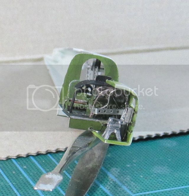


Honest, the fuselage halves really do come together in real life.


Honest, the fuselage halves really do come together in real life.
RedDuster

Joined: March 01, 2010
KitMaker: 7,078 posts
AeroScale: 118 posts

Posted: Wednesday, April 29, 2015 - 11:28 PM UTC
Hi Jim,
Sorry for the delay in reply, the rigging is copper wire, stripped out of electrical cables and rolled straight under a metal rule.
Great builds going on, must remember to look in more frequently.
Just posted a couple of pics of the Tiggie in the Gallery.
Si
Sorry for the delay in reply, the rigging is copper wire, stripped out of electrical cables and rolled straight under a metal rule.
Great builds going on, must remember to look in more frequently.
Just posted a couple of pics of the Tiggie in the Gallery.
Si

Stoker

Joined: February 07, 2015
KitMaker: 58 posts
AeroScale: 19 posts

Posted: Sunday, May 03, 2015 - 05:00 AM UTC
Hi Everybody,
Quick update on my Silver Star, I have the cockpit completed and have started on the main body. All of the landing gear bays have been painted. Started to assemble the body when I realized that I didn't paint the exhaust tube Hope to have more progress by the end of the week
Ron

Quick update on my Silver Star, I have the cockpit completed and have started on the main body. All of the landing gear bays have been painted. Started to assemble the body when I realized that I didn't paint the exhaust tube
 Hope to have more progress by the end of the week
Ron

 |


