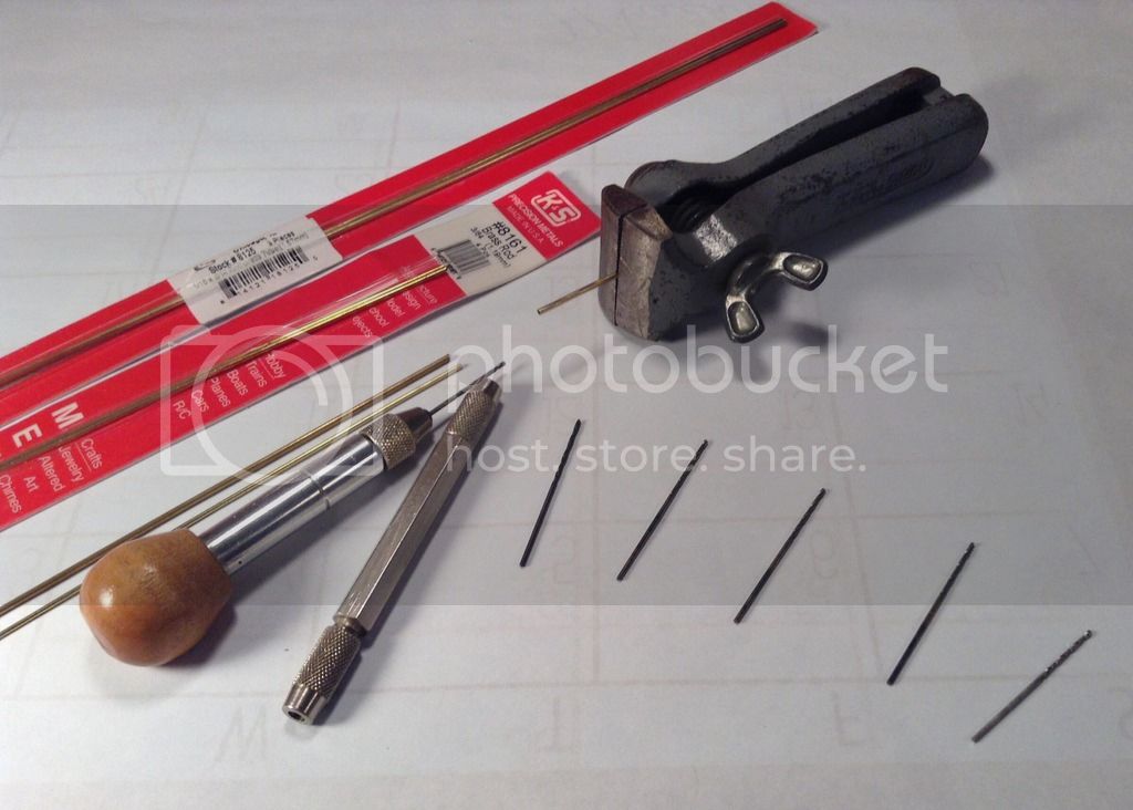
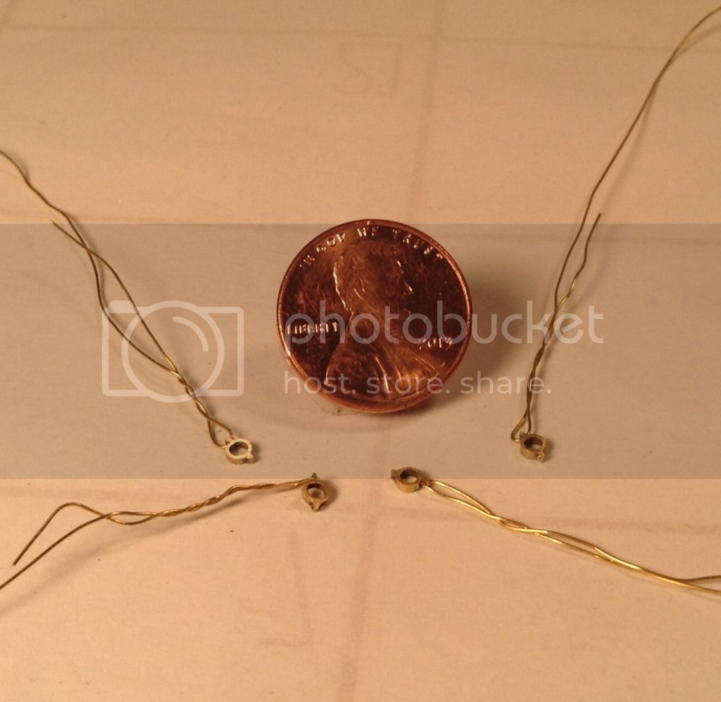
I've begun the next component- the starter shaft . The first pieces I chose to make were the four collars located in pairs at each end of the shaft. Since the shaft itself will be made of 1/16 " o.d. tubing I used a piece of 3/32" o.d. tubing for the collars themselves as the i.d. is 1/16" and slides over the 1/16" tubing. I split one end of the 3/32" tube with a razor saw for a short distance and inserted two small strips cut from a piece of 1/64" x 1/4" brass strip to represent the ears on the collars. A piece of 1/16" tube was inserted temporarily in the tube to prevent the strips from interfering with the bore. The split tube/strip unit was wired together at one end and soldered after removing the temporary tube.
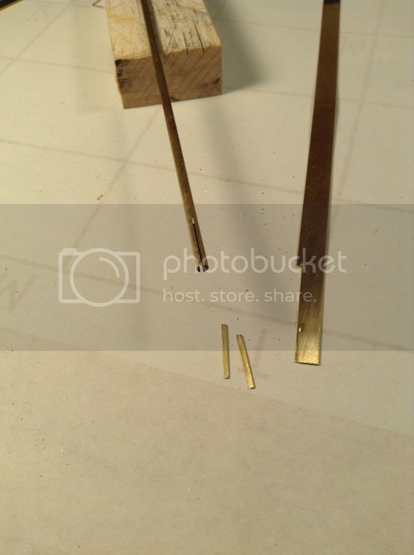
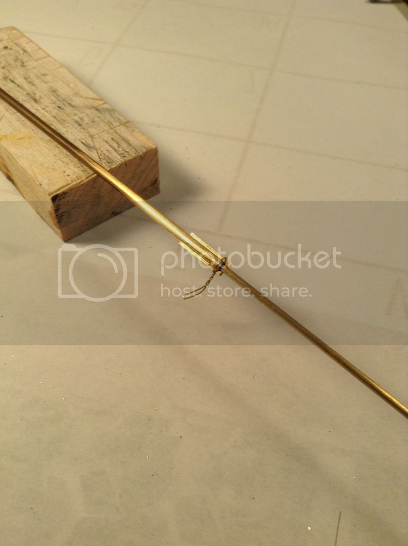
Small holes were drilled in the ears to later accept a piece of wire for bolt detail and then the collars were sliced of with a razor saw and reduced in thickness by rubbing on a piece of 600 grit sandpaper on the glass plate. A short wire tag was threaded through the ear holes on each in an effort to avoid feeding the carpet monster.
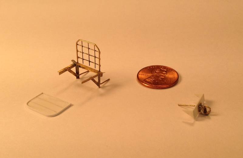
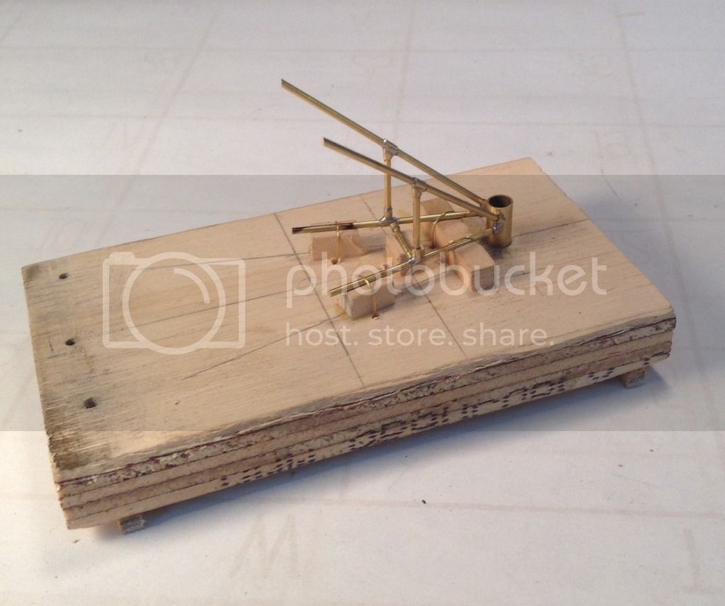
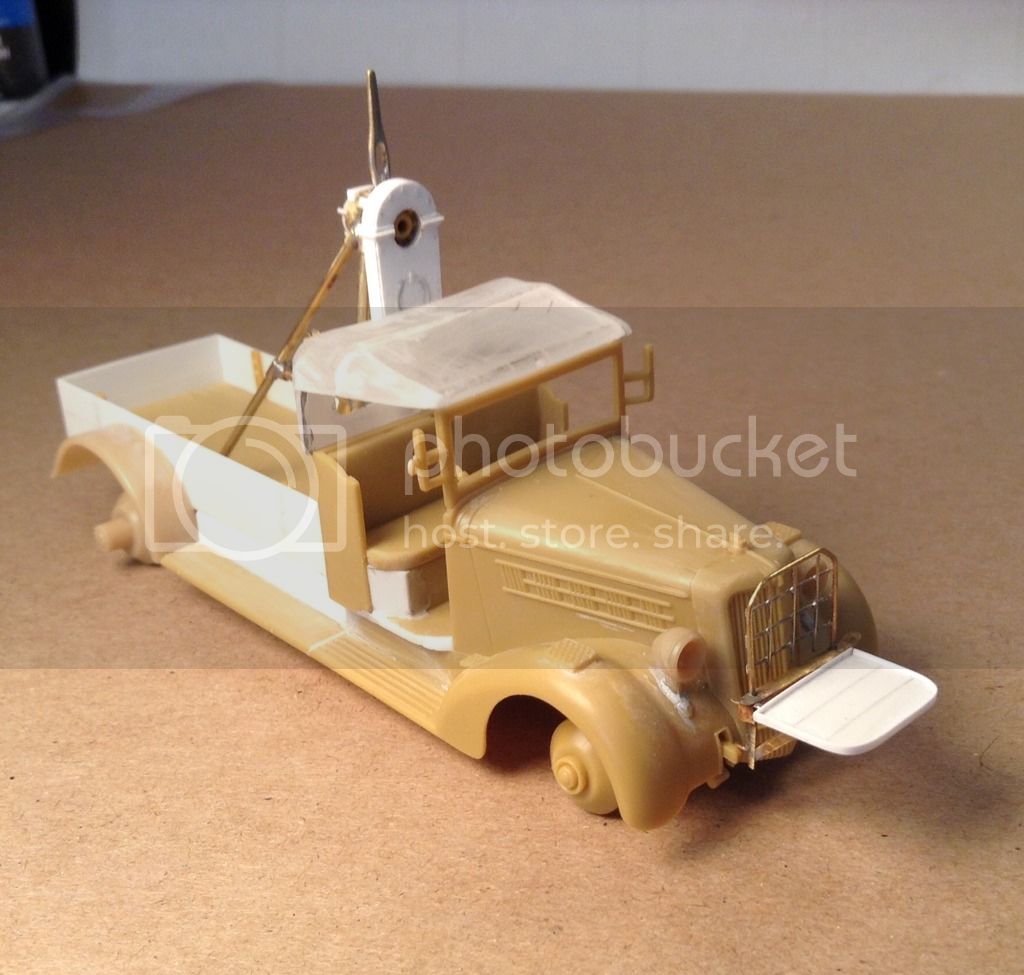
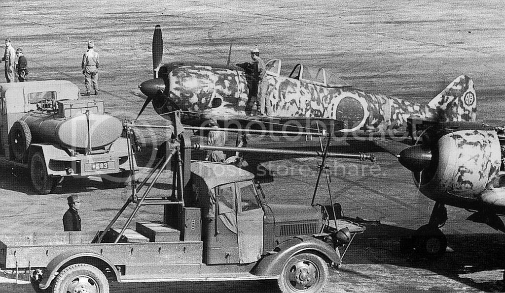
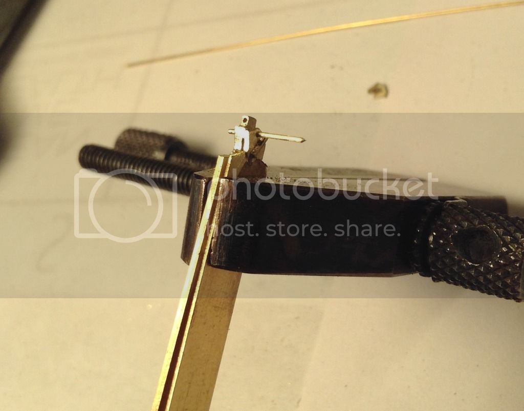
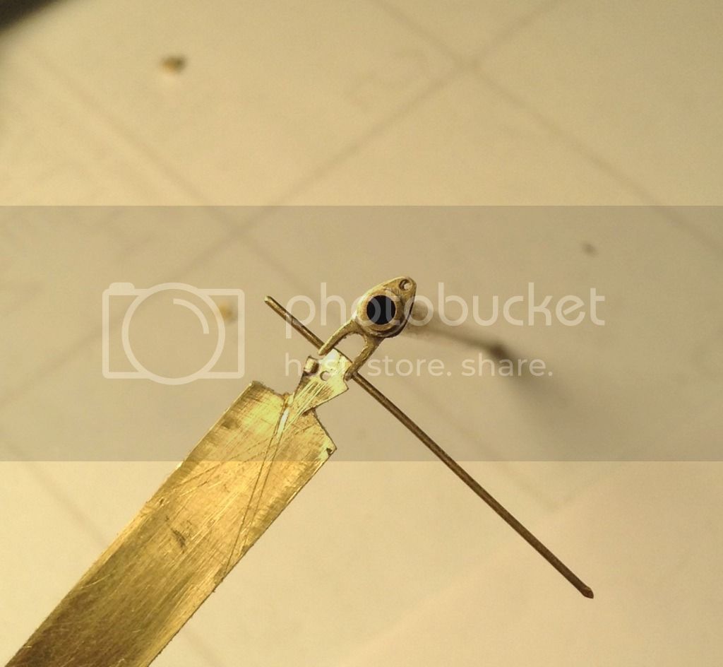
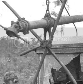
The next piece made was the hanging shaft bearing for the outboard end of the shaft. This component consists of a tube with two pear shaped plates on the top which connect to a chain hanging from the boom and two small legs on the bottom which tie into the two shear poles that stand from the front platform.
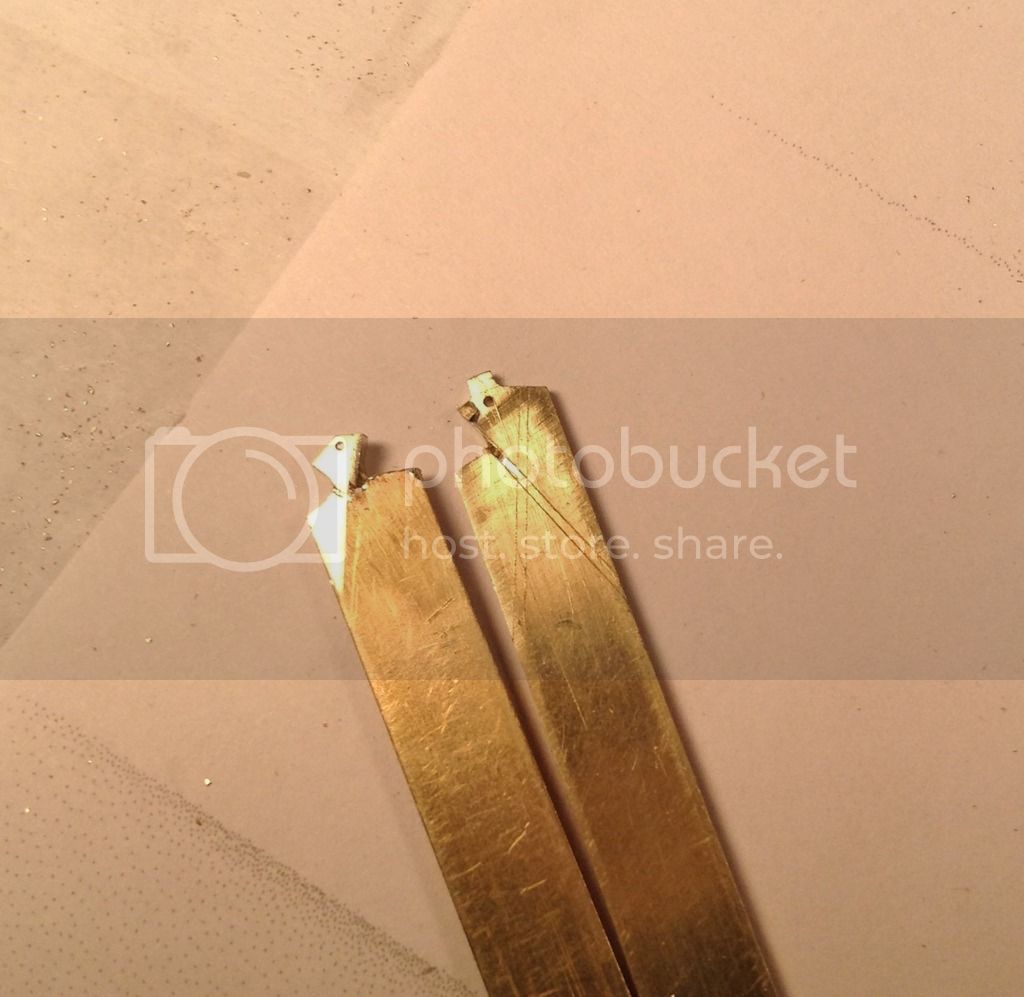
A piece of 1/64" x 1/4" brass strip was crosscut nearly all the way through and folded over itself so that both pieces could be bored and roughed out together to minimize asymmetry.
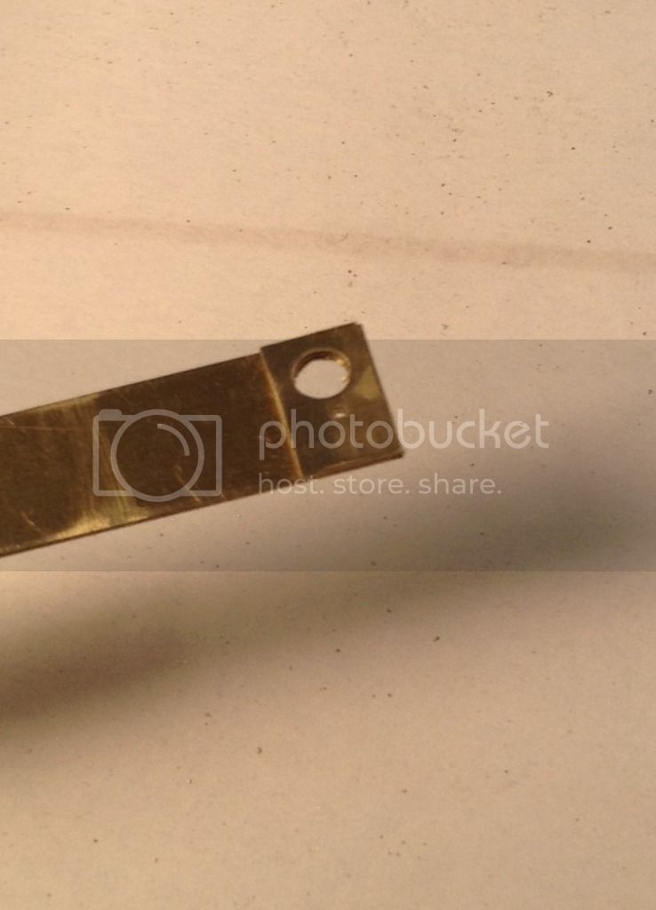
Next a piece of 1/32" brass strip was bored with a 3/32" dia hole to accept a piece of 3/32" tubing, two legs were roughed out with a jeweler's saw and files, and then soldered to the tube.
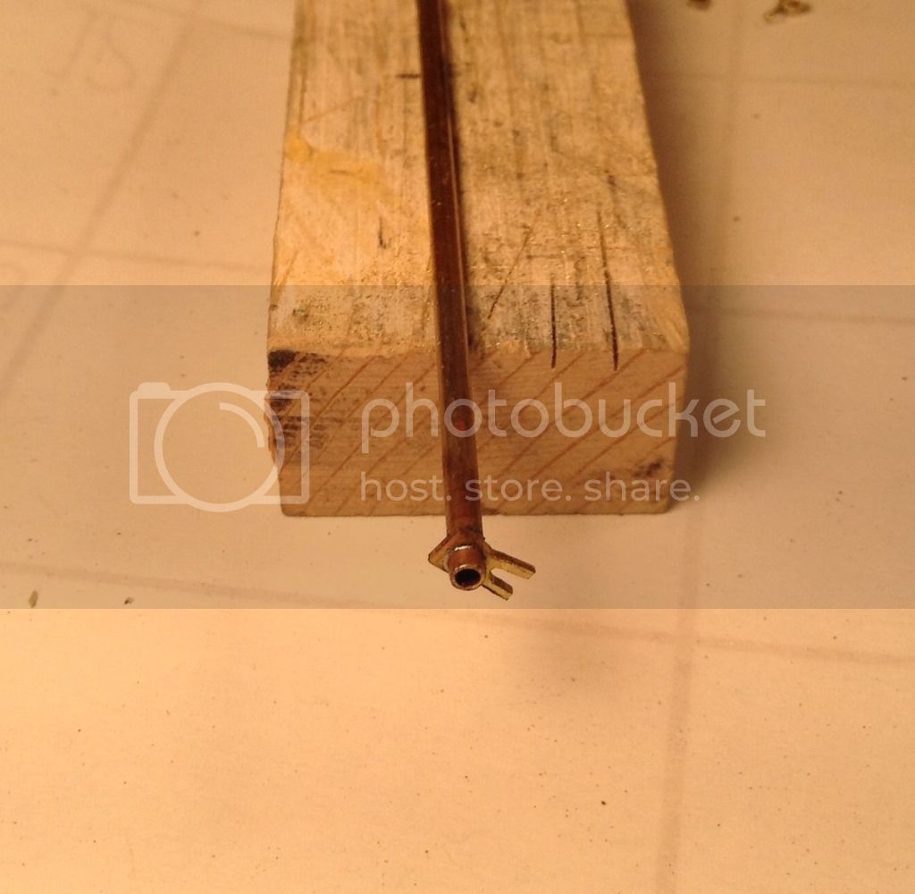
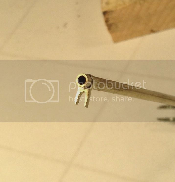
The two pear shaped plates were then roughed to shape, split apart,and then soldered on each side of the leg piece. Final shaping was done with files and sandpaper after soldering to the tube.
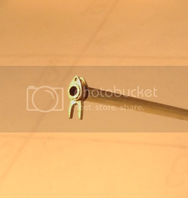
This piece will be sawn off the tubing after the lower end of the legs have their shear pole connections finalized which I am a little in the dark about because I have't found a clear photo of the back side of this piece.
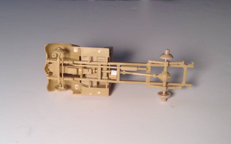
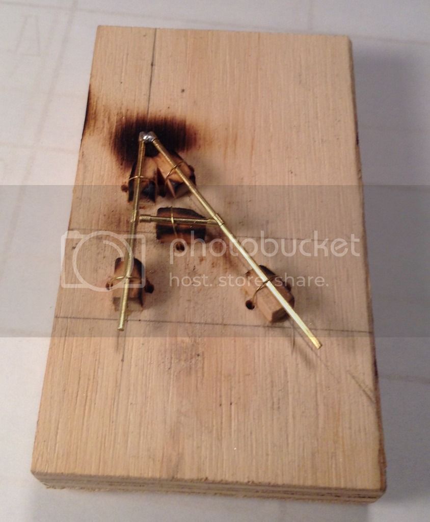
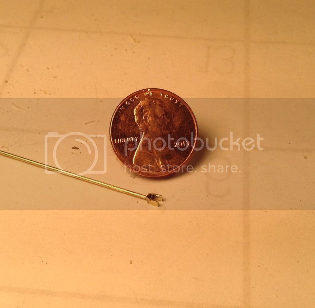
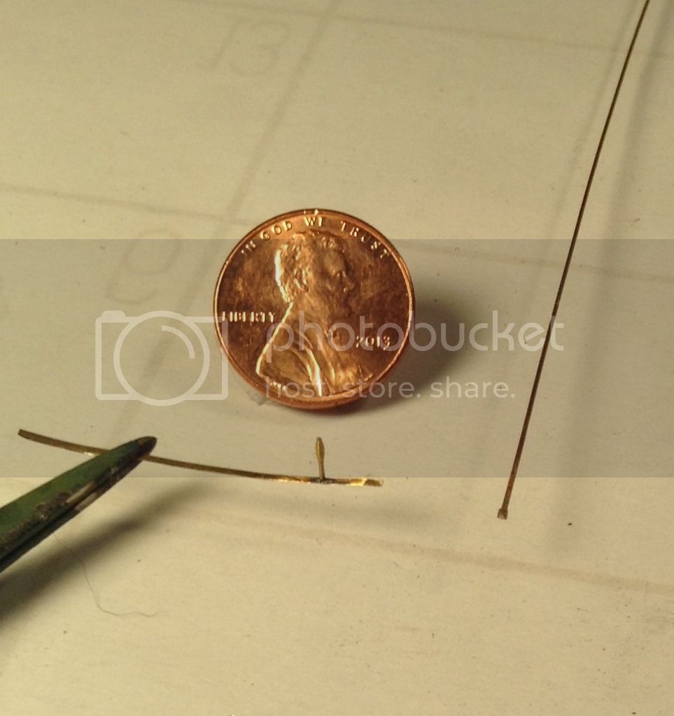
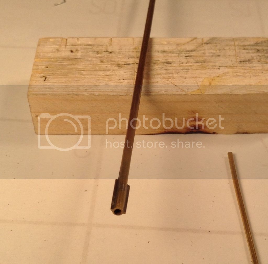
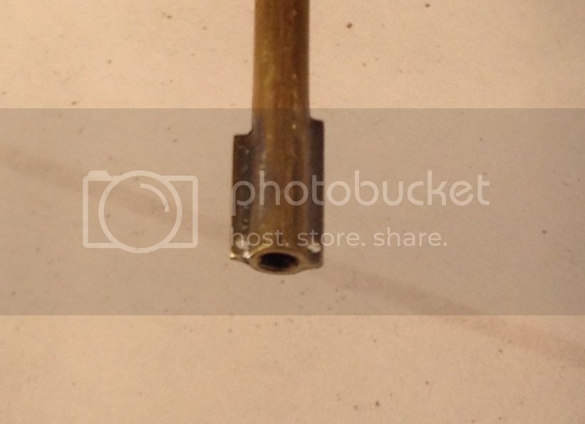
The last piece made was the shaft itself which is simply a piece of 1/16" o.d. tube cut to length with a piece of brass rod inserted in the back end and soldered and then chucked in the lathe to have the slight taper filed to shape on the inboard end. Here are all the shaft components so far-
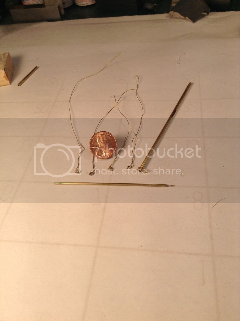
Next will be the telescoping shaft with it's universal joints and coupler that inserts into the outboard end of the shaft. Hopefully the photo fairy will come and clear up the shear poles connection- till then all comments welcome and Thanks for looking- Cheers ! Richard