

Hi Richard,
I'm at a loss for words!! You sir, have some incredible skills! The amount of detail and the minute size of the part you are creating continues to amaze me.
I eagerly await the next update. Keep up the amazing work - and thank you for sharing.
Regards,
Kobus
General Aircraft
This forum is for general aircraft modelling discussions.
This forum is for general aircraft modelling discussions.
Hosted by Jim Starkweather
Hucks type starter truck build

Kilo_Uniform

Joined: July 03, 2015
KitMaker: 280 posts
AeroScale: 141 posts
Posted: Thursday, May 05, 2016 - 09:57 AM UTC
rdt1953

Joined: February 06, 2015
KitMaker: 1,098 posts
AeroScale: 900 posts
Posted: Friday, May 06, 2016 - 02:11 AM UTC
Kobus - thank you yet again for your compliments. Sharing this has been great fun so far ! Richard
rdt1953
Joined: February 06, 2015
KitMaker: 1,098 posts
AeroScale: 900 posts
Posted: Saturday, May 07, 2016 - 07:55 PM UTC
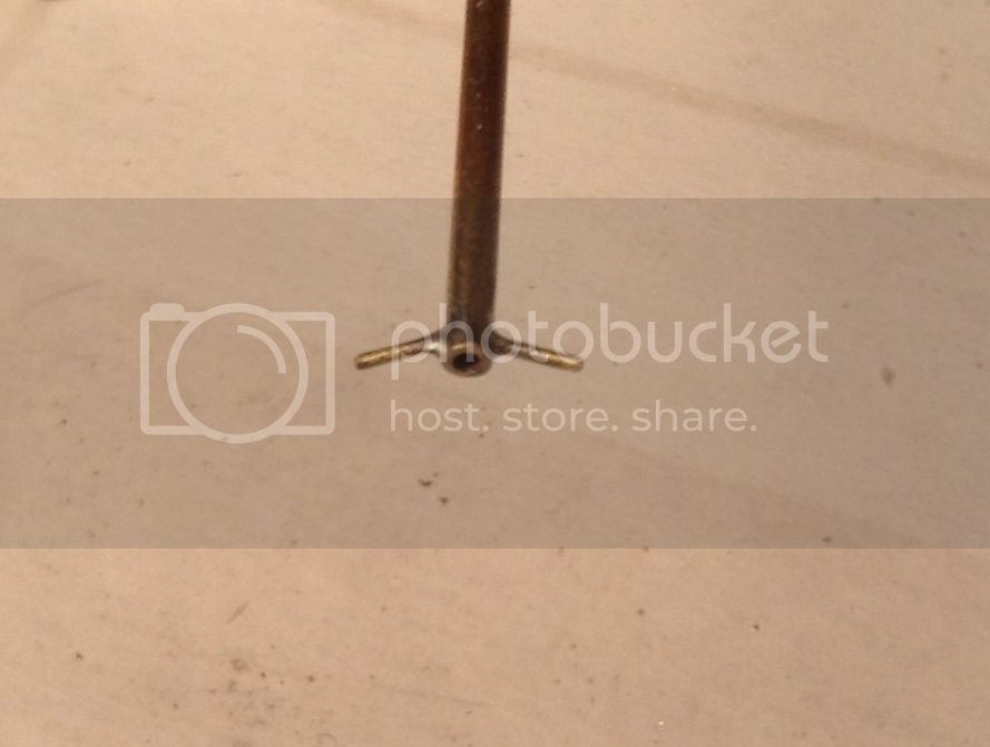
I have been granted a brief tme out from Mother's Day duty to post this progress update. I have completed the shear pole clamp fixtures and installed the clamp to the hanging shaft bearing. First up is the large wingnut that is situated on the inboard end of the pinch bolt. This is simply a piece of brass tube with a hole bored through one end and a short length of rod inserted. The wings of the rod were bent slightly then soldered.
Next we have the hanging bearing with all the clamp components spread out along the pinch bolt which will be left overlength for the time being.From left to right we see the wingnut, the hanging bearing with the rear clamp plate, the intermediate clamp plate, the small outer clamp dog and the pinch bolt with it's handle.

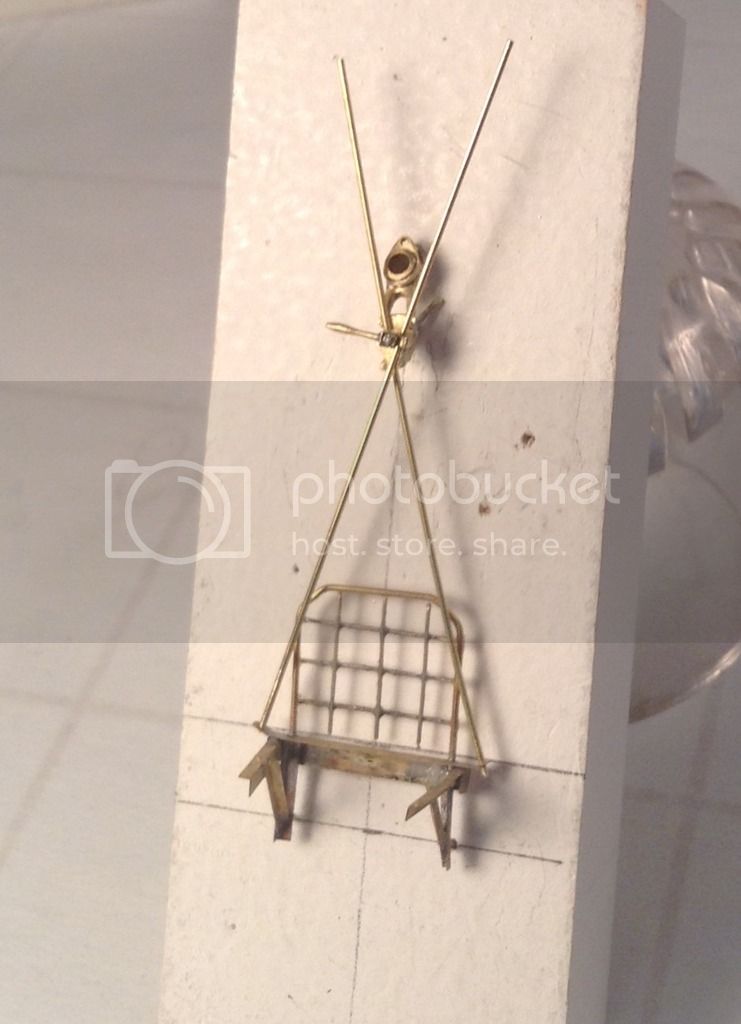
Here are the hanging bearing/clamp fixture, shear poles and front platform framework set in a temporary jig to check progress.
Next will be the completion of the shaft itself with the installation of the four ring clamps, the hanging bearing and three small rings which form thestops for the bearing and the slight bell at the end of the shaft.
Thanks for looking ! Richard
Next we have the hanging bearing with all the clamp components spread out along the pinch bolt which will be left overlength for the time being.From left to right we see the wingnut, the hanging bearing with the rear clamp plate, the intermediate clamp plate, the small outer clamp dog and the pinch bolt with it's handle.
Here are the hanging bearing/clamp fixture, shear poles and front platform framework set in a temporary jig to check progress.
Next will be the completion of the shaft itself with the installation of the four ring clamps, the hanging bearing and three small rings which form thestops for the bearing and the slight bell at the end of the shaft.
Thanks for looking ! Richard

Redhand

#522
Joined: January 20, 2013
KitMaker: 1,460 posts
AeroScale: 1,443 posts
Posted: Saturday, May 07, 2016 - 09:00 PM UTC
Your metalwork continues to amaze. I'm in awe.
chukw1
Joined: November 28, 2007
KitMaker: 817 posts
AeroScale: 729 posts
Posted: Saturday, May 07, 2016 - 11:43 PM UTC
I'm sadly late to this party! Brilliant work, Richard- I'm impressed! Forgive me if you know this tip already, but you can protect joins from nearby soldering with bit of wet paper towel. I learned that and a few other nifty ideas here: http://www.modelersalliance.com/forum/yasuyuki-watanabe

rdt1953
Joined: February 06, 2015
KitMaker: 1,098 posts
AeroScale: 900 posts
Posted: Sunday, May 08, 2016 - 01:53 AM UTC
Quoted Text
Your metalwork continues to amaze. I'm in awe.
Brian - Thank you again for the kind words . This type of work is really within the capabilities of most modelers who have done some scratchbuilding. The working of the brass just takes longer because of its hardness as compared to styrene . I find I use silicone carbide sandpipers backed by flat steel rules or brass shapes or on the glass plate for flattening these days more than files when I can. The brass can be sawn with a jewelers saw or razor saw just as plastic can - it just takes more time. The soldering itself is not that difficult with a little practice- The difficulty lies in keeping the parts in the correct relationship with each other while being torched so you must devise jigs, fixtures etc. The reward is the brass components with their small joint surfaces are much stronger where a similar glued joint in plastic may fail.
Give it a try sometime- looking at what you have created in your build I'm certain you can do it. I use styrene whenever I can because it is faster , easier and even more appropriate in some applications but things like the front platform on this truck would be very difficult to render in plastic and still have a delicate appearance. Horses for courses as they say. Thanks for following . Richard
rdt1953
Joined: February 06, 2015
KitMaker: 1,098 posts
AeroScale: 900 posts
Posted: Sunday, May 08, 2016 - 02:07 AM UTC
Quoted Text
I'm sadly late to this party! Brilliant work, Richard- I'm impressed! Forgive me if you know this tip already, but you can protect joins from nearby soldering with bit of wet paper towel. I learned that and a few other nifty ideas here: http://www.modelersalliance.com/forum/yasuyuki-watanabe
Chuck- thank you for the compliments and the tips. While I have heard of the wet paper towel trick I have not tried it and I think it's time I did. Hard, medium and soft jewelers silver solders are the way to go but I am foolishly too parsimonious to by them. Also, I can no longer get the inbox cylinders for my micro flame torch so I am using an inexpensive butane model which does not have as hot or as fine a flame.I believe it may have been you who did the wonderful Helldiver blog which someone recently posted a link to. If I am correct a tip of the hat to you sir- beautiful work and a very entertaining series. Thanks again - Richard
rdt1953
Joined: February 06, 2015
KitMaker: 1,098 posts
AeroScale: 900 posts
Posted: Sunday, May 08, 2016 - 03:11 AM UTC
Thanks to the curse of autocomplete " by " should read " buy" and " inbox" should read " inox " - Richard
rdt1953
Joined: February 06, 2015
KitMaker: 1,098 posts
AeroScale: 900 posts
Posted: Sunday, May 15, 2016 - 01:21 AM UTC
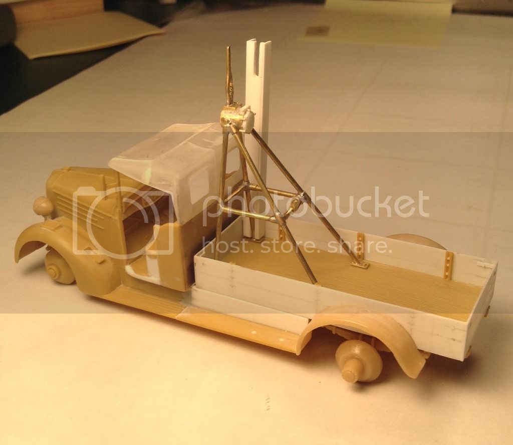
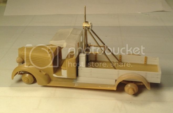
A little more progress to share with everyone. I have completed the starter shaft and the telescoping shaft with it's universal joint and coupler that engages the dog on the propeller hub. Completion of the main part of the shaft entailed simply sliding the previously made collars,etc into position and then fastening all with medium CA with the exception of the hanging bearing which was left unfastened so the shaft will turn and slide axialy.
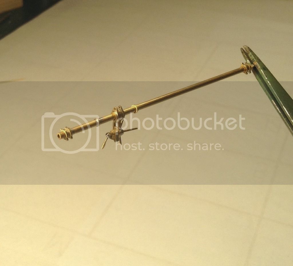
Next the coupler was made by filing two ears on a piece of brass tube. The ears were then cross drilled for the universal joint pin and the corners of the ears radiused. Another hole was drilled through the main body of the coupler oriented 90 degrees to the previous hole to accept the coupler bar/handles. This is shown here with the previously made telescoping shaft and it's yoke.
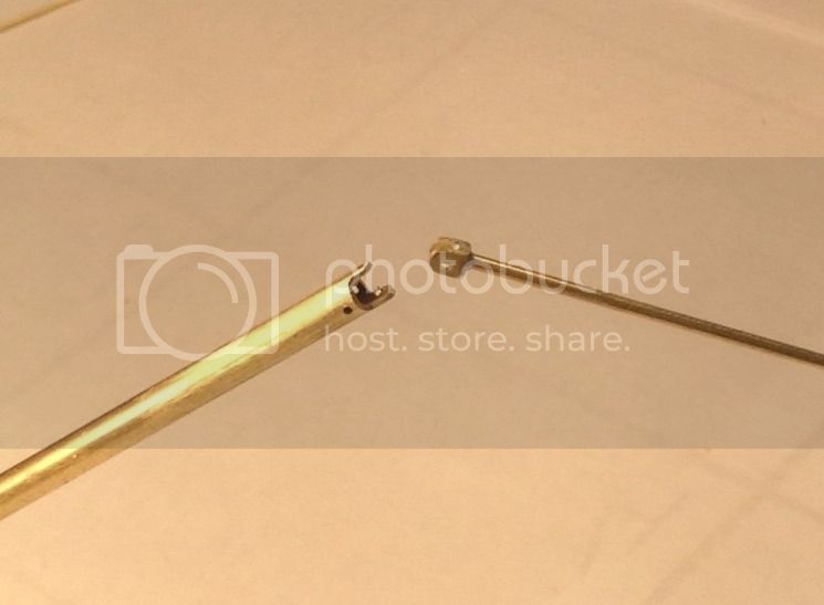
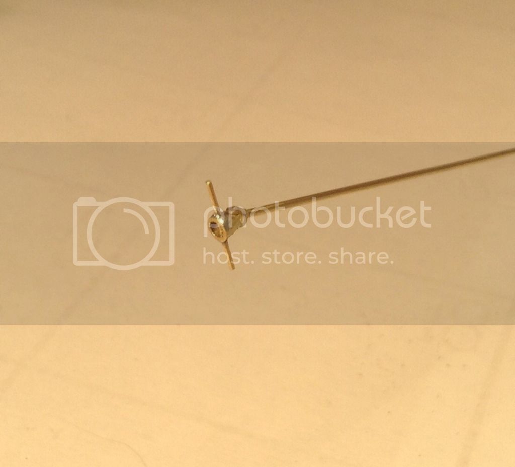
A piece of brass wire was inserted through the coupler and soldered to form the coupler bar/handles. Yet to make are the two small collars seen in the photo at the inboard end of the handles and seated against the coupler body. On the actual truck this bar engages cam type slots in the dog at the prop hub. When the rpm of the starter shaft exceeds the rpm of the prop as it would when starting the aircraft engine the slots assure the coupler will drive towards the prop and keep it engaged. When the aircraft's engine starts and it's rpm exceeds that of the coupler these slots then assure the coupler bar gets ejected back towards the truck. I assume the telescoping shaft and the bore of the main shaft are splined.
A small length of brass tube was cut to fit between the yoke and cross drilled for the pin at the coupler and all were riveted together with brass rod.
Lastly we see the complete shaft assembly.

I will likely start on the boom assembly next but I am approaching the time when the front platform will have to be permanently attached to the truck and this means painting/washing/highlighting the radiator and shell and the back of the platform as it will difficult to do after the platform is attached. Thanks for looking and all comments/input welcome.
Cheers ! Richard
Next the coupler was made by filing two ears on a piece of brass tube. The ears were then cross drilled for the universal joint pin and the corners of the ears radiused. Another hole was drilled through the main body of the coupler oriented 90 degrees to the previous hole to accept the coupler bar/handles. This is shown here with the previously made telescoping shaft and it's yoke.
A piece of brass wire was inserted through the coupler and soldered to form the coupler bar/handles. Yet to make are the two small collars seen in the photo at the inboard end of the handles and seated against the coupler body. On the actual truck this bar engages cam type slots in the dog at the prop hub. When the rpm of the starter shaft exceeds the rpm of the prop as it would when starting the aircraft engine the slots assure the coupler will drive towards the prop and keep it engaged. When the aircraft's engine starts and it's rpm exceeds that of the coupler these slots then assure the coupler bar gets ejected back towards the truck. I assume the telescoping shaft and the bore of the main shaft are splined.
A small length of brass tube was cut to fit between the yoke and cross drilled for the pin at the coupler and all were riveted together with brass rod.
Lastly we see the complete shaft assembly.
I will likely start on the boom assembly next but I am approaching the time when the front platform will have to be permanently attached to the truck and this means painting/washing/highlighting the radiator and shell and the back of the platform as it will difficult to do after the platform is attached. Thanks for looking and all comments/input welcome.
Cheers ! Richard
Redhand
#522
Joined: January 20, 2013
KitMaker: 1,460 posts
AeroScale: 1,443 posts
Posted: Sunday, May 15, 2016 - 04:09 AM UTC
Again, Richard, this work is just amazing. You show enormous creativity in doing this. It just blows me away seeing these delicate parts hand made out of literally nothing but bits of brass.
rdt1953
Joined: February 06, 2015
KitMaker: 1,098 posts
AeroScale: 900 posts
Posted: Sunday, May 15, 2016 - 08:18 PM UTC
Quoted Text
Again, Richard, this work is just amazing. You show enormous creativity in doing this. It just blows me away seeing these delicate parts hand made out of literally nothing but bits of brass.
Brian - Thanks again for your compliments and thanks also for following along - Richard
amegan

#243

Joined: March 21, 2008
KitMaker: 996 posts
AeroScale: 915 posts

Posted: Monday, May 16, 2016 - 04:19 AM UTC
I built a Russian one from a kit to match my Polikarpov I-15
I think I got the kit from Hannants and I still have the truck if you want any detail photos. btw I use PhotoRazor to reduce photo size ti 800x600 before posting
I think I got the kit from Hannants and I still have the truck if you want any detail photos. btw I use PhotoRazor to reduce photo size ti 800x600 before posting
rdt1953
Joined: February 06, 2015
KitMaker: 1,098 posts
AeroScale: 900 posts
Posted: Tuesday, May 17, 2016 - 03:19 AM UTC
Quoted Text
I built a Russian one from a kit to match my Polikarpov I-15
I think I got the kit from Hannants and I still have the truck if you want any detail photos. btw I use PhotoRazor to reduce photo size ti 800x600 before posting
Andrew - Thanks for the offer- I don't know if any of the details on your Russian truck are applicable but I would love to see it anyway ! Cheers - Richard
rdt1953
Joined: February 06, 2015
KitMaker: 1,098 posts
AeroScale: 900 posts
Posted: Sunday, May 22, 2016 - 06:16 AM UTC
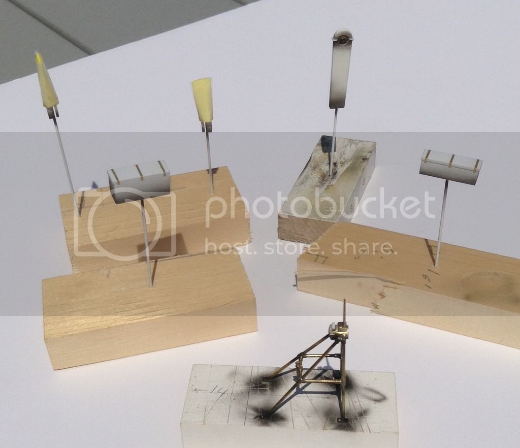
Very little progress this week to report. I have started work on the two chests that sit in the bed beneath the mast assembly. These are simply two boxes of two different sizes built up of sheet styrene and edged with styrene
as well. I have also made up the horizontal angle brackets with bolt detail at the back of the bed- the bolts have yet to be trimmed and the chests need to have strap detail added across their tops. Chests are shown here loosely dry fitted.


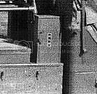
While in chest mode I will also make the two small vertical units that stand on either side of the mast at the forward end of the bed. I believe these may contain fire extinguishers as the copy of Hasegawa's 1/72 Hucks truck instructions which I have call out for these boxes to painted red- If anyone out there can confirm or deny this I would be grateful.
Thanks for looking- Cheers ! Richard
as well. I have also made up the horizontal angle brackets with bolt detail at the back of the bed- the bolts have yet to be trimmed and the chests need to have strap detail added across their tops. Chests are shown here loosely dry fitted.
While in chest mode I will also make the two small vertical units that stand on either side of the mast at the forward end of the bed. I believe these may contain fire extinguishers as the copy of Hasegawa's 1/72 Hucks truck instructions which I have call out for these boxes to painted red- If anyone out there can confirm or deny this I would be grateful.
Thanks for looking- Cheers ! Richard
rdt1953
Joined: February 06, 2015
KitMaker: 1,098 posts
AeroScale: 900 posts
Posted: Monday, May 30, 2016 - 06:40 AM UTC
Some more progress to report thanks to a long weekend - not the least of which is to hold in remembrance those who gave all .
I have bored four holes in the flanges at the base of the mast unit and located four corresponding brass pins in the bed.

I next glued up " C " channel of styrene to form the casework for the two upright chests at the front of the bed - these needed slots to clear the forward legs of mast.

I next cut the channel to hieght for the two chests and added tops and doors of styrene.
To create what seems to be ventilation registers of some sort I pierced a piece of brass shim on a block of soft wood with a sewing needle and sanded off the raised portion on the back side- a small steel scale was used to control spacing and keep the holes in line.
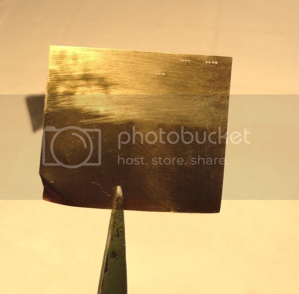
The registers were then cut to size with sharp scissors and cemented to the doors with CA. Small toggle latches were cut from styrene and cemented as well.
Three straps of brass were added to the tops of the two horizontal chests. Here we see all of the chests.

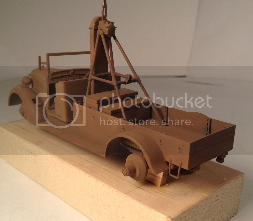
Since the time has come to start adding fragile details to the truck I had to make a base so it could be handled while minimizing the chance of knocking parts off. I first made two bent aluminium strips with holes that correspond with the hubs on the brake drums and in the process of fitting I very clumsily broke the front axle. I hope the repair will hold but if not I will have to replace it with the axle from the second kit. The second try produced something very similar to the soldering fixtures - blocks glued at the axle locations with holes drilled through straddling the blocks. The truck was then wired to the base with brass wire.
Two steps were bent up of brass wire and had their upper ends flattened with hammer and punch. These were cemented to the bed behind the rear fenders.
Here then is all the work to date loosely dry fitted- some components are a little askew but will hopefully be trued up at perminent assembly.


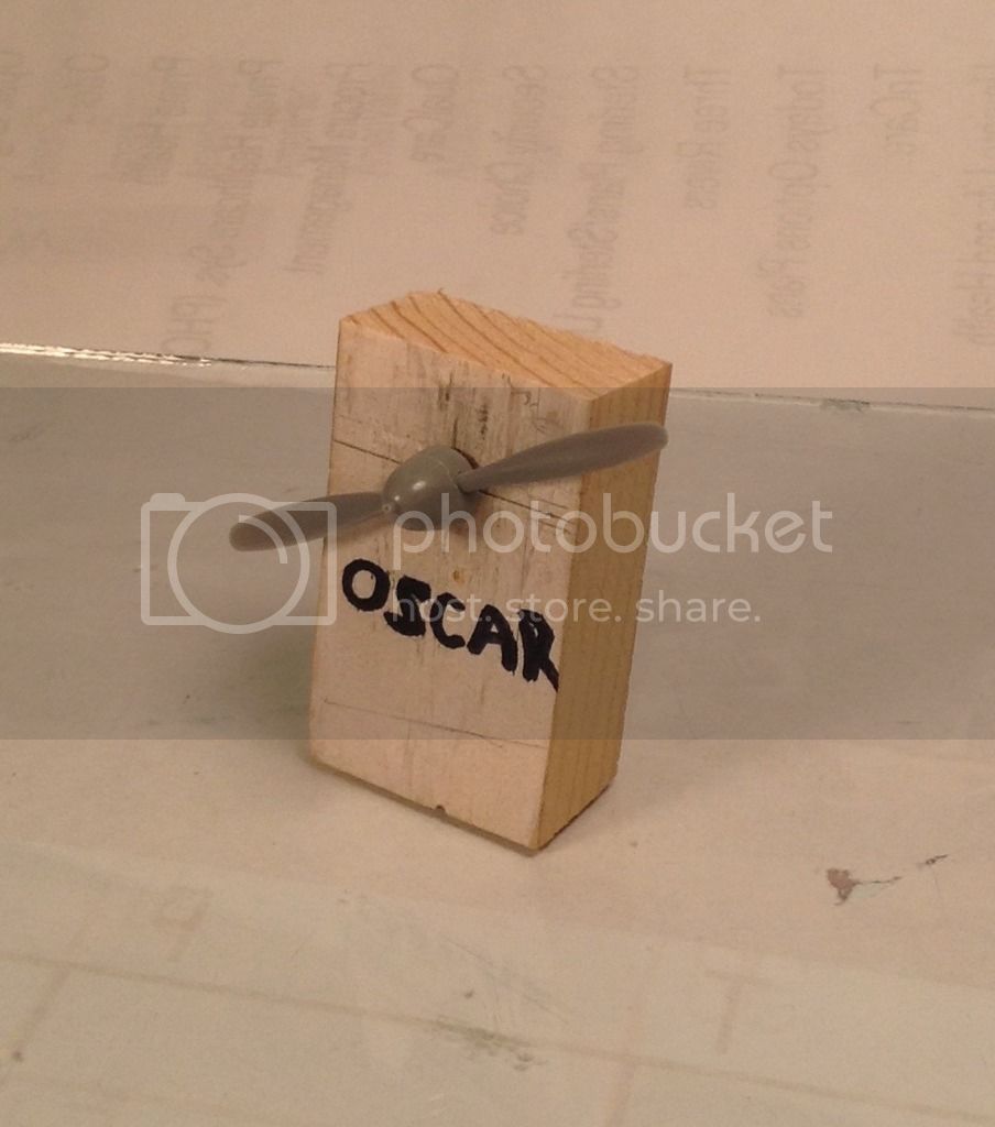
With an eye toward a future diorama I have pulled an Oscar from the stash and will tape enough of it togther to determine the hieght of the prop center so that I may fix the hieght of the starter shaft . Once this is established I will start on the boom system and then will need to start some preliminary paintwork that needs doing prior to permanent assembly of some components- Thanks for looking and as always I welcome all input . Cheers ! Richard
I have bored four holes in the flanges at the base of the mast unit and located four corresponding brass pins in the bed.
I next glued up " C " channel of styrene to form the casework for the two upright chests at the front of the bed - these needed slots to clear the forward legs of mast.
I next cut the channel to hieght for the two chests and added tops and doors of styrene.
To create what seems to be ventilation registers of some sort I pierced a piece of brass shim on a block of soft wood with a sewing needle and sanded off the raised portion on the back side- a small steel scale was used to control spacing and keep the holes in line.
The registers were then cut to size with sharp scissors and cemented to the doors with CA. Small toggle latches were cut from styrene and cemented as well.
Three straps of brass were added to the tops of the two horizontal chests. Here we see all of the chests.
Since the time has come to start adding fragile details to the truck I had to make a base so it could be handled while minimizing the chance of knocking parts off. I first made two bent aluminium strips with holes that correspond with the hubs on the brake drums and in the process of fitting I very clumsily broke the front axle. I hope the repair will hold but if not I will have to replace it with the axle from the second kit. The second try produced something very similar to the soldering fixtures - blocks glued at the axle locations with holes drilled through straddling the blocks. The truck was then wired to the base with brass wire.
Two steps were bent up of brass wire and had their upper ends flattened with hammer and punch. These were cemented to the bed behind the rear fenders.
Here then is all the work to date loosely dry fitted- some components are a little askew but will hopefully be trued up at perminent assembly.
With an eye toward a future diorama I have pulled an Oscar from the stash and will tape enough of it togther to determine the hieght of the prop center so that I may fix the hieght of the starter shaft . Once this is established I will start on the boom system and then will need to start some preliminary paintwork that needs doing prior to permanent assembly of some components- Thanks for looking and as always I welcome all input . Cheers ! Richard
Redhand
#522
Joined: January 20, 2013
KitMaker: 1,460 posts
AeroScale: 1,443 posts
Posted: Monday, May 30, 2016 - 06:27 PM UTC
It continues to have all the makings of a masterpiece. Really.
rdt1953
Joined: February 06, 2015
KitMaker: 1,098 posts
AeroScale: 900 posts
Posted: Tuesday, May 31, 2016 - 05:24 AM UTC
Quoted Text
It continues to have all the makings of a masterpiece. Really.
Brian- Thanks for all the compliments - I'm glad you're following this . Richard
rdt1953
Joined: February 06, 2015
KitMaker: 1,098 posts
AeroScale: 900 posts
Posted: Friday, June 03, 2016 - 07:54 AM UTC
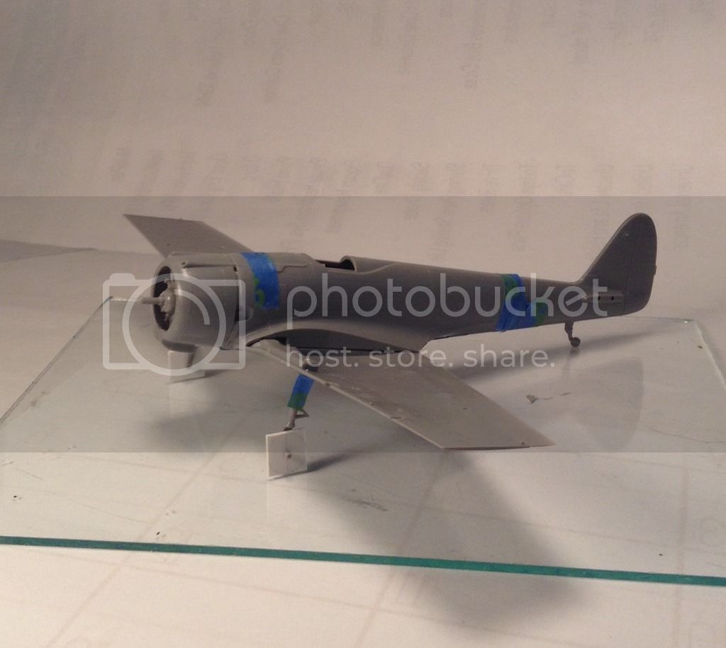
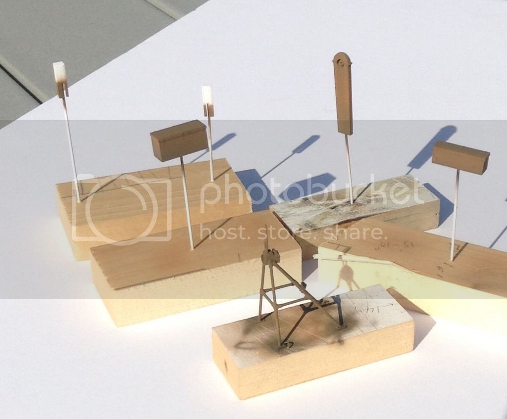
A brief update - I have temporarily thrown enough of Hasegawa's early Oscar together to determine the the propeller's height / thrust angle relative to the ground while in a static three point attitude. The fuselage and lower wing section were simply taped together while the cylinder banks/crankcase assembly were temporarily glued with aliphatic resin ( impressive name for Elmer's white glue ) . The main landing gear oleos and yoke/ spindle units were glued together permanently with Tamiya liquid cement. Hasegawa molded these in two pieces in a clever but structurally weak way so that both the left and right gear could be made from the same moldings- duplicate sprues - with the oleo scissor torque links trailing aft the yoke/ spindle units are rotated 180 degrees and cemented to the oleos with an interlocking cruciform key arrangement. Given the inherent weakness of not much more than a simple butt joint at this critical location I let this joint cure for a few days before continuing.
Each mainwheel and tire are composed of three pieces only one of which-the backing plate- fits tightly around wheel spindle. Since I did not want to permanently assemble these and with the floppy nature of them being only dry fitted I elected to cut two squares of styrene equal to the tire diameter wth a centered hole equal to the spindle diameter to represent the mainwheels.
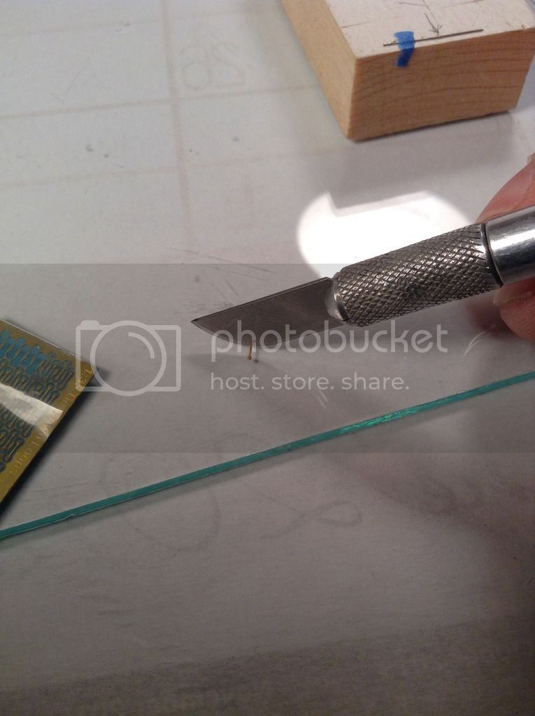
With the Oscar now sitting on it's gear I crosscut a bevel on a block of wood so the face of the block stood perpendicular to the propeller shaft while the bottom edge of the block rested on the glass plate which represents the ground surface. While in this position I marked the center height of the prop shaft on the edge of the block and squared this point across the face. A hole was bored along this line at the center of the face to accept the prop shaft and propeller.
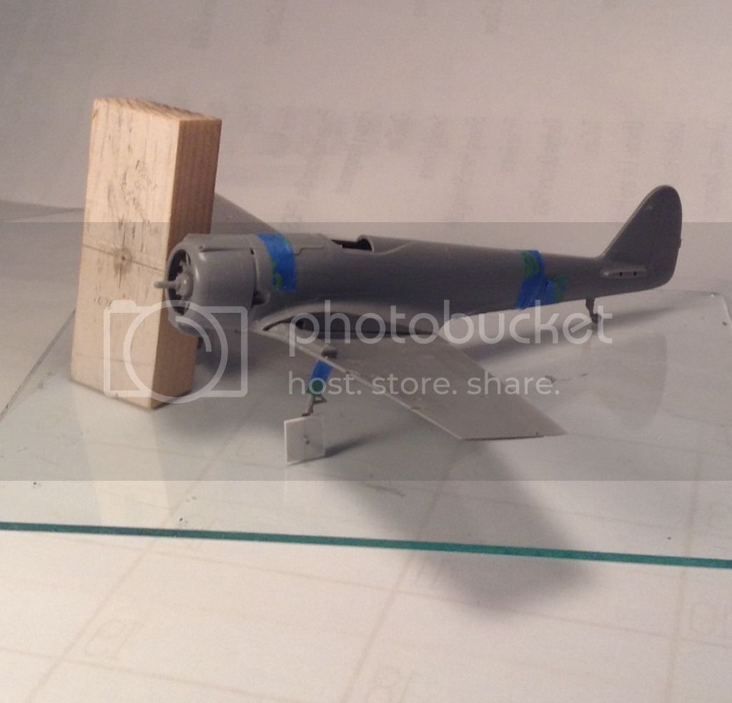
Here we now have a fixture for setting the hieght of the starter shaft.
Thanks for looking ! - Richard
Each mainwheel and tire are composed of three pieces only one of which-the backing plate- fits tightly around wheel spindle. Since I did not want to permanently assemble these and with the floppy nature of them being only dry fitted I elected to cut two squares of styrene equal to the tire diameter wth a centered hole equal to the spindle diameter to represent the mainwheels.
With the Oscar now sitting on it's gear I crosscut a bevel on a block of wood so the face of the block stood perpendicular to the propeller shaft while the bottom edge of the block rested on the glass plate which represents the ground surface. While in this position I marked the center height of the prop shaft on the edge of the block and squared this point across the face. A hole was bored along this line at the center of the face to accept the prop shaft and propeller.
Here we now have a fixture for setting the hieght of the starter shaft.
Thanks for looking ! - Richard
rdt1953
Joined: February 06, 2015
KitMaker: 1,098 posts
AeroScale: 900 posts
Posted: Sunday, June 12, 2016 - 12:17 AM UTC
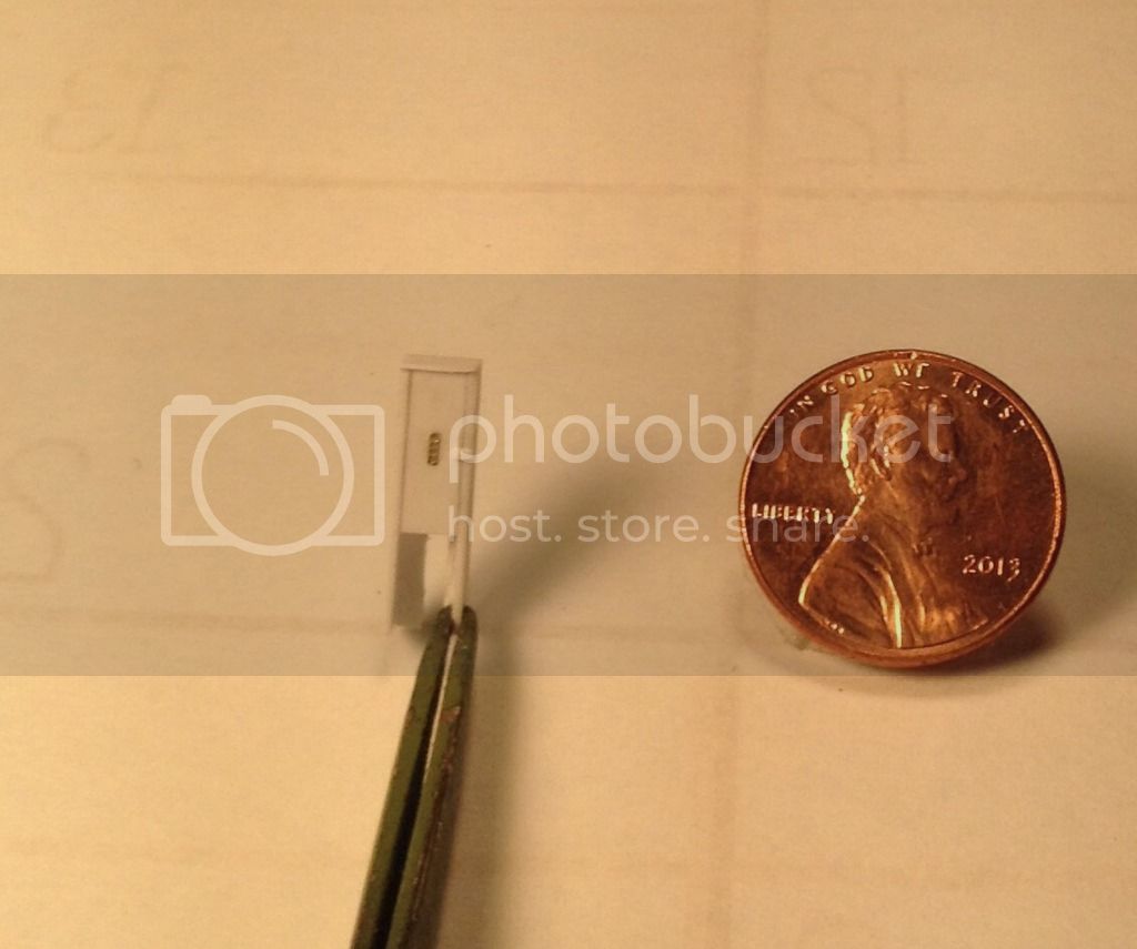
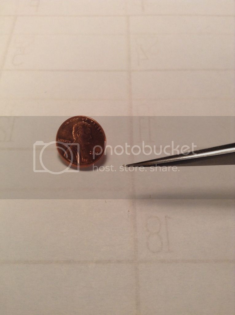
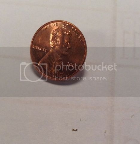
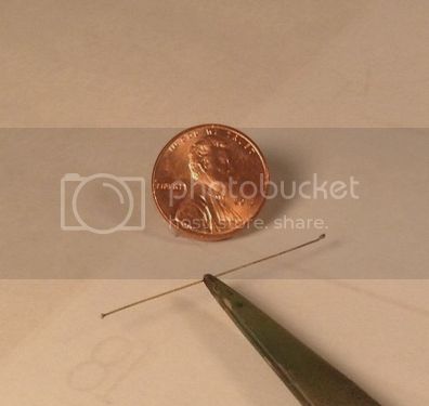
Brief update-A task I have been dreading due to its tedium and repetition is now behind me. I have made the 14 tiny tiedown hooks that surround the bed plus a few spares in anticipation of the inevitable tweezer launch.
I used the fixed end strap brackets from the Alliance Modelworks 1/35 allied tie down set . These have a dogbone shape in their flattened state.

The bolt detail was first cut away from one end leaving a straight strip with bolt detail at the bottom.
I made a bending fixture by taping a # 80 drill bit to a block of wood and drilling a hole in the block along side the bit to accept the bottom end of the tiedown. The hole depth was determined by trial and error until it left just enough of the tie down protruding to bend around the bit 180 degrees.

Here is the finished product-
If the crack team of optical surgeons are able to restore my ruined eyesight I will then seek some professional help to try to regain my lost sanity -
Cheers and thanks for looking ! Richard
I used the fixed end strap brackets from the Alliance Modelworks 1/35 allied tie down set . These have a dogbone shape in their flattened state.
The bolt detail was first cut away from one end leaving a straight strip with bolt detail at the bottom.
I made a bending fixture by taping a # 80 drill bit to a block of wood and drilling a hole in the block along side the bit to accept the bottom end of the tiedown. The hole depth was determined by trial and error until it left just enough of the tie down protruding to bend around the bit 180 degrees.
Here is the finished product-
If the crack team of optical surgeons are able to restore my ruined eyesight I will then seek some professional help to try to regain my lost sanity -
Cheers and thanks for looking ! Richard
rdt1953
Joined: February 06, 2015
KitMaker: 1,098 posts
AeroScale: 900 posts
Posted: Sunday, June 26, 2016 - 04:05 AM UTC
Real life adult stuff and summer fun have limited modeling activity but I have managed to make some more progress. As I have used two kits for the starter truck I had enough spare components to throw together a fuel truck as a study for painting. I had used the treadplate components from the fuel truck for various details on the starter truck so I replaced these with sheet styrene on the study model. I purchased a Tamiya Superfine double action airbrush and as this is my first experience with double action I felt some practice couldn't hurt. I first pre shaded with Tamiya XF 1 Flat Black mixed 50/50 with 91% isopropyl alcohol. I mixed Tamiya XF 49 Khaki with XF 64
Red Brown at a 2 to 1 ratio for the IJAAF brown base color. The first highlight was done with the base color mix lightened with Tamiya XF 60 Dark Yellow sprayed in halo pattern.
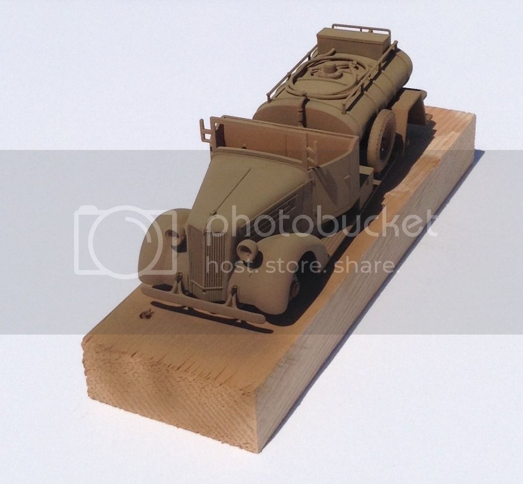
I have pre shaded the Hucks truck -


and the chests and mast/chaincase -
The chests and mast/chaincase have also been sprayed with base color.
next will be some base color at the front of the truck and the bed interior so the chests and mast/chaincase can be permanently attached .
Thanks for looking - Cheers ! Richard
Red Brown at a 2 to 1 ratio for the IJAAF brown base color. The first highlight was done with the base color mix lightened with Tamiya XF 60 Dark Yellow sprayed in halo pattern.
I have pre shaded the Hucks truck -
and the chests and mast/chaincase -
The chests and mast/chaincase have also been sprayed with base color.
next will be some base color at the front of the truck and the bed interior so the chests and mast/chaincase can be permanently attached .
Thanks for looking - Cheers ! Richard
Kilo_Uniform
Joined: July 03, 2015
KitMaker: 280 posts
AeroScale: 141 posts
Posted: Sunday, June 26, 2016 - 09:58 AM UTC
Hi Richard,
Simply awesome! Looking forward to seeing it with some colour.
Regards,
Kobus
Simply awesome! Looking forward to seeing it with some colour.
Regards,
Kobus
rdt1953
Joined: February 06, 2015
KitMaker: 1,098 posts
AeroScale: 900 posts
Posted: Sunday, June 26, 2016 - 11:59 PM UTC
Quoted Text
Hi Richard,
Simply awesome! Looking forward to seeing it with some colour.
Regards,
Kobus
Kobus - Thank you ! I'm glad I did the study model for painting as I am on my 3rd try on it but I am getting closer to what I had in mind - Thanks for following along.
Cheers ! Richard
rdt1953
Joined: February 06, 2015
KitMaker: 1,098 posts
AeroScale: 900 posts
Posted: Saturday, July 02, 2016 - 06:59 PM UTC
A little more progress to report - I have added the two small knobs on each side of the cab on the outside at the base beneath the seat. I believe these may be PTO controls to engage/disengage the starter shaft. Small rectangular plates of styrene were cemented to the cab and then drilled to accept the shaft. The knobs and their shafts were formed by tiny drop of solder on the ends of a piece of brass wire then shaped with sandpaper. The shafts were then cut to length and inserted in their respective holes and fastened wth medium CA.
I have also added the 14 tiny tiedown hooks around the perimeter of the bed. After laying out their locations they were tacked in place with a tiny dot of 5 minuit epoxy and then backed up with thin CA. By some miracle only the first one was sent into the abyss by tweezer launch - the rest went much easier than expected.
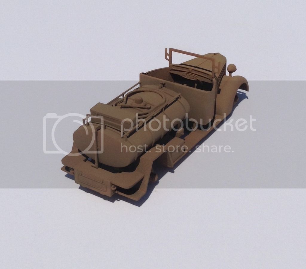
So here then is the truck itself with preshading in black and the first application of the base color.

Here is the study model with 3 different tones added- I'm afraid it does not show well in the photos but looks much better in acctuality.
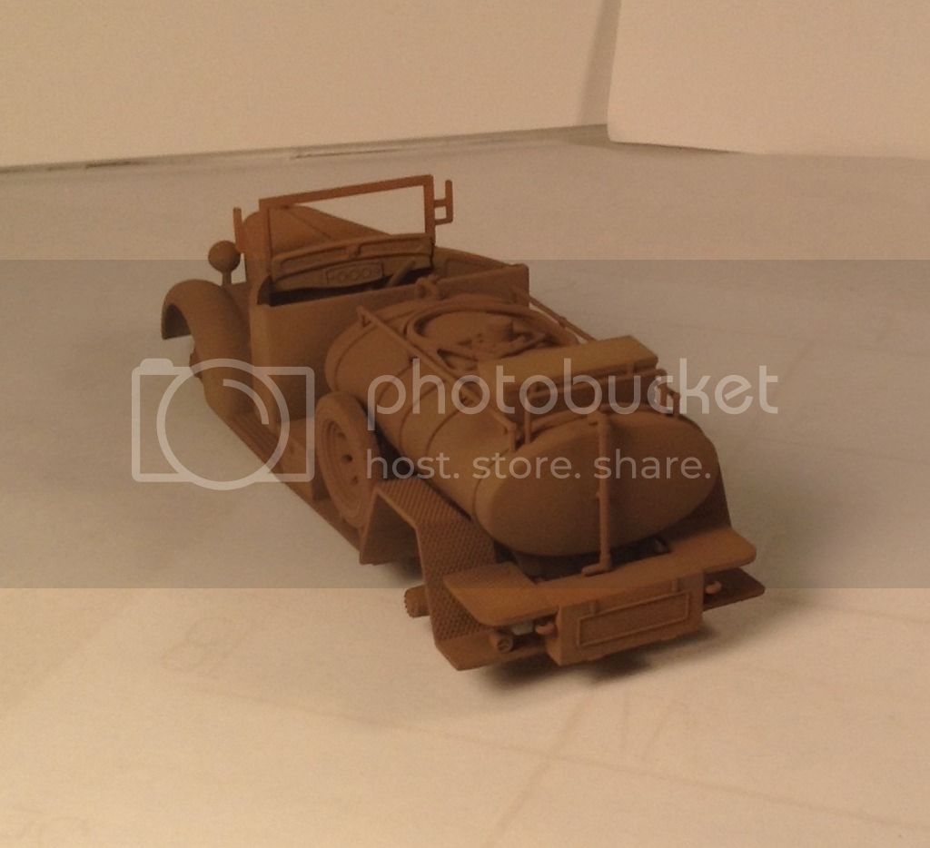
And a few tires to paint- uggh !

Next will be some lighter tones and maybe a pinwash around the grill area in preparation for the mounting of the front platform.
Thanks for looking ! - Richard
I have also added the 14 tiny tiedown hooks around the perimeter of the bed. After laying out their locations they were tacked in place with a tiny dot of 5 minuit epoxy and then backed up with thin CA. By some miracle only the first one was sent into the abyss by tweezer launch - the rest went much easier than expected.
So here then is the truck itself with preshading in black and the first application of the base color.
Here is the study model with 3 different tones added- I'm afraid it does not show well in the photos but looks much better in acctuality.
And a few tires to paint- uggh !
Next will be some lighter tones and maybe a pinwash around the grill area in preparation for the mounting of the front platform.
Thanks for looking ! - Richard
Redhand
#522
Joined: January 20, 2013
KitMaker: 1,460 posts
AeroScale: 1,443 posts
Posted: Saturday, July 02, 2016 - 08:04 PM UTC
I have never seen anyone create and manipulate tiny parts the way you do. Your craftsmanship is extraordinary, like you are a jewelry maker in real life. Can't wait to see the next steps.
heavyjagdpanzer
Joined: February 17, 2013
KitMaker: 173 posts
AeroScale: 108 posts
Posted: Saturday, July 02, 2016 - 09:45 PM UTC
Your work is museum quality, simply amazing!
 |

WEB HOSTING BY


Copyright ©2021 AeroScale and Kitmaker Network, a subsidiary of Silver Star Enterprises
All Rights Reserved. Please read our Conditions of Use and Privacy Policy.
All Rights Reserved. Please read our Conditions of Use and Privacy Policy.