

1⁄32Silver Wings Fairey Flycatcher Build
4
Comments
Fuselage Assembly
Fuselage assembly is covered by steps 21 and 22 in the instructions.Begin the fuselage assembly be deciding if you want your pilot access doors in the open of closed position. Note that the pilot access doors slide down into the fuselage when opened. Silver Wings kindly provides two thinner doors to be used in the open position, and two thicker doors for the closed position. I opted to have the starboard access door closed, and the port access door opened.
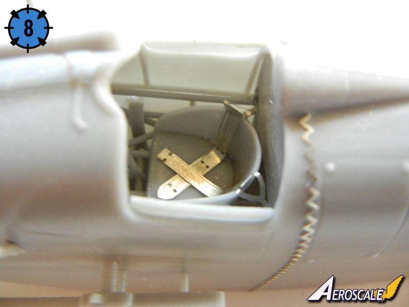
■ Attach the pilot's access doors in the desired position. Photo 8 shows one open and one closed on the completed fuselage assembly.
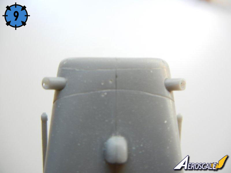
■ Attach the two tubes to the lower forward fuselage as indicated. Photo 9 shows then in the installed position.
■ Dry fit the cockpit and rear cockpit bulkhead into position. Once you are satisfied with the fit, remove the rear bulkhead and attach the seatbelts if you did not do so in step 8 and glue into position.
■ Install the completed cockpit frame to one of the fuselage halves. Push the ammo feed chute into the correct position and secure it to the fuselage side.
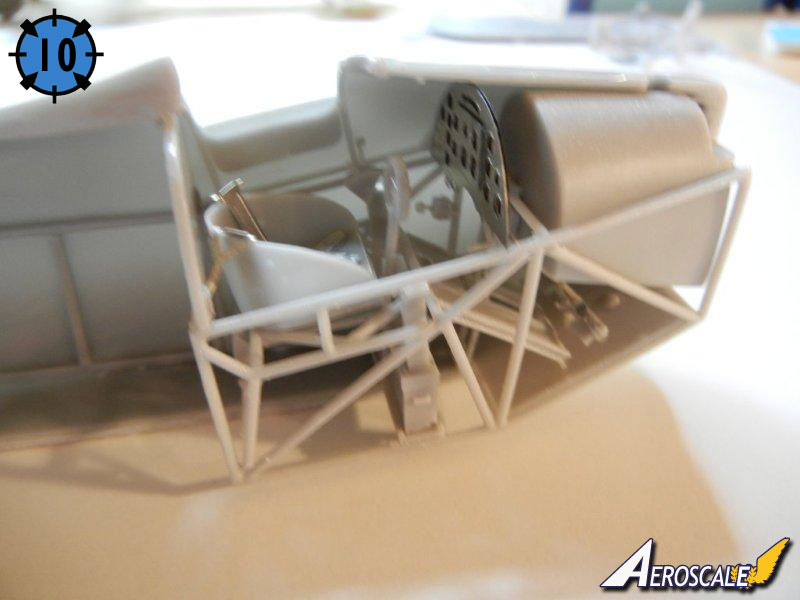
■ Test fit your trimmed IP (or scratch built IP) to the fuselage half, it's position indicated by the bracket on the fuselage half side framing. Glue into position when satisfied with the fit. Photo 10 shows the IP in position.
■ Glue the fuselage halves together, ensuring the cockpit frame and rear bulkhead are in the correct position.
■ Using a piece of rod, styrene, etc. push the remaining ammo magazine feed chute into position and glue in place.
■ Once set, attach the PE stitching in the appropriate positions as indicated in the instructions. I noted that the PE parts were slightly long, so I dry fit and trimmed them as appropriate before gluing into place. As an alternative, both Archer transfers and HGW offer alternative, easy to use, stitching as well.
■ I recommend waiting to install the guns, windscreen, gunsight and tailskid until later in the build.
Engine Assembly
Engine assembly is covered by steps 17 ~ 20 of the instructions. The engine of the Flycatcher is quite visible as there is no cowl, but fortunately Silver Wings gives us a beautiful rendition of the Jaguar III/IV engine. You will need to check your references to see which exhaust your kit should have and use the appropriate parts.■ I began assembly by attaching the back row of cylinders, being sure that each was facing exactly forward.
■ Note that when looking at the engine from the front, the left side pushrod is attached to the engine block in front of the right side pushrod. I cut one of the pushrods and test fit it to the engine block/cylinder head in the rear (right side) position and found that it was too long, so I trimmed one to fit, and then made another 6 to match. I then attached all of the rear (right side) pushrods to the engine block/cylinder heads.
■ I then test fit another pushrod to the left side (front) and trimmed it to fit, and again made 6 to match. I then fit them into position as well. Note that for either side, some pushrods did require slight trimming to ensure a good fit.
■ I added the front row of cylinders to the engine.
■ Once set, I began attaching the intake pipes which fit to the left side of the cylinder heads (when viewed from the front) and to the mounting base. The longer leg of the intake pipes goes to the front row of cylinders. I had to bend mine slightly together to get the proper fit.
■ Once finished, I repeated the process above to attach the pushrods to the front cylinders, again going left over right at the engine block base.
■ I added the two parts that go on the top and bottom of the front of the engine block.
■ Attach the appropriate exhaust pipes for your model.
■ If using the short exhaust pipes, you may want to place the engine temporarily on the taped together fuselage to get the alignment of the two upper section exhausts correct. After that, you can attach all the small tubes pointing upwards and outwards to the remaining positions.
■ If using the long exhaust pipes, you can attach the collectors at this point. You can temporarily place the engine on the taped together fuselage in order to determine the length of spacing rod to attach to the exhaust pipes for mounting to the outer fuselage. I would recommend marking the position of attachment and drilling out a hole, which will allow you to attach a longer rod that can be pushed into the hole and adjusted for optimal fit during the final assembly.
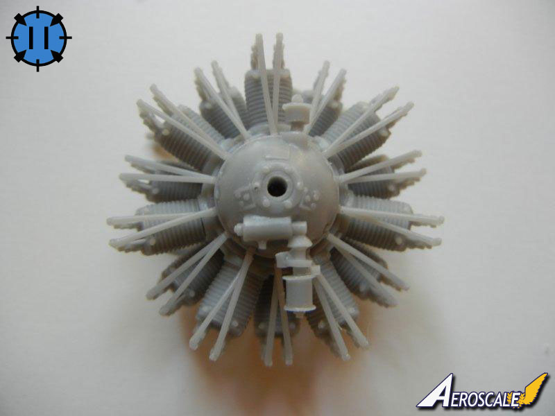
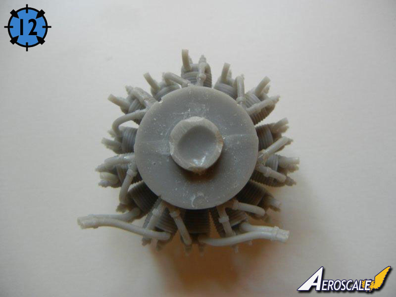
■ Photos 11 and 12 show the completed engine.
About the Author


FROM: GEORGIA, UNITED STATES
I've been modeling on and off for over 40 years. My primary interests are WW1, Interwar and WW2 aircraft, although I do build an occasional WW2 armour kit. I used to build 1/32 kits back in the 80's, but switched to 1/48 in the early 90's when all the nice new kits started showing up. I've sinc...
Comments

Fabulous review Doug and you have just tipped the scales for me in deciding whether or not to buy one of these superb models. The review will be a great reference when it finally gets built.
Off to Paypal we go.....!
Best regards
Gary
FEB 18, 2012 - 05:00 AM


Thank you Doug for this build article, I've been contemplating on this kit and watching Rowan's build. I think my mind is now made up, stop thinking and buy it
FEB 18, 2012 - 04:11 PM
Copyright ©2021 by Doug Nelson. Images also by copyright holder unless otherwise noted. The views and opinions expressed herein are solely the views and opinions of the authors and/or contributors to this Web site and do not necessarily represent the views and/or opinions of AeroScale, KitMaker Network, or Silver Star Enterrpises. Images also by copyright holder unless otherwise noted. Opinions expressed are those of the author(s) and not necessarily those of AeroScale. All rights reserved. Originally published on: 2011-11-12 00:00:00. Unique Reads: 8562

WEB HOSTING BY


Copyright ©2021 AeroScale and Kitmaker Network, a subsidiary of Silver Star Enterprises
All Rights Reserved. Please read our Conditions of Use and Privacy Policy.
All Rights Reserved. Please read our Conditions of Use and Privacy Policy.