

1⁄32Silver Wings Fairey Flycatcher Build
4
Comments
Lower wings
The ailerons and "butt joined" to the lower wings. I left them this way for this build guide to see how they would hold up. I am happy to report they have remained in place without issue with lots of handing (not just by me). However, I would recommend that you mark and drill out holes in the mating surfaces for two or three brass/wire rods. This will give you both the advantage of a stronger join, and the ability to easily deflect the ailerons if desired.■ Begin by drilling out the strut (and rigging if desired) attachment holes in the lower wings as indicated. See the article "Making Templates" in the "Tips and Reviews" section of the Silver Wings website (www.silverwings.pl) for tips on drilling out these holes at the correct angle.
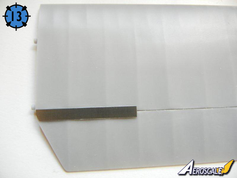
■ Attach the ailerons into position. Once dry, attach the PE plates (PE12) as indicated (see photo 13).
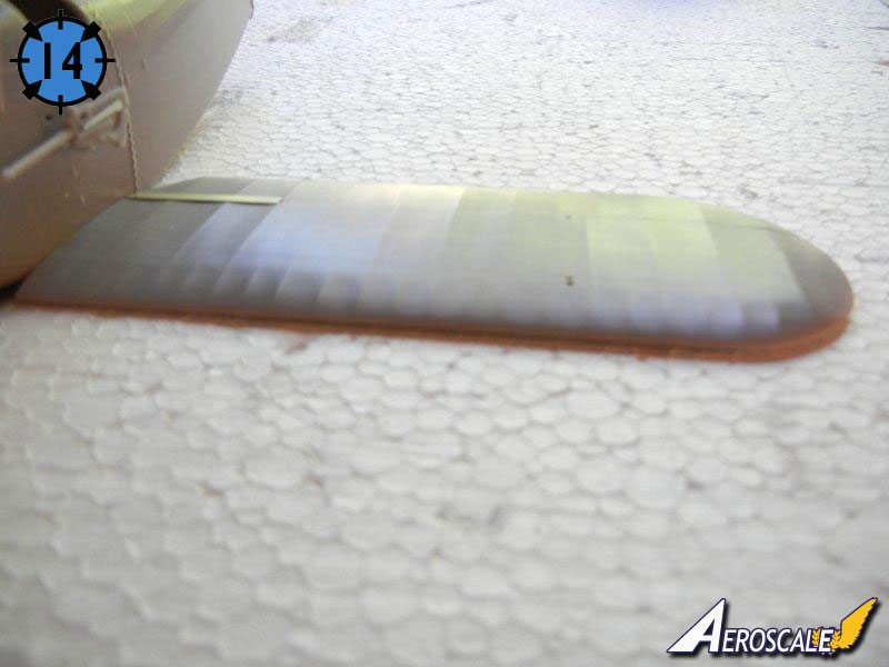
■ When set, attach the wings to the completed fuselage assembly. As the lower wings should have 0 dihedral, you can use a flat surface to help keep them level (see photo 14).
■ I recommend waiting to install the control cable guides to the bottom of the wing until final assembly.
Upper wings and wing attachment
Note that I assembled my kit using the 13mm dihedral indicated in the instructions, and only after the wing was set, did I note that there appeared to be too much dihedral in the top wing and followed up with Silver Wings to determine the correct measurement (11mm).Like the lower wings, the ailerons are "butt joined" to the upper wings. If you used the brass/wire rod option suggested above, you should also do so for these wings.
■ Again, begin by drilling out the holes for the struts (and rigging if desired) in the fuselage, center and outer upper wings.
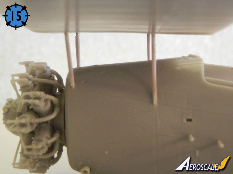
■ Dry fit the cabane (wing to fuselage) struts to the fuselage, and then test fit the upper wing center section (see photo 15). On my example, I found the rear cabane struts (the longer set) to be a little long, and I had to press them down into the fuselage holes to get the proper wing position. However, as the correct 11mm dihedral will raise the center wing section, you may actually find the forward cabane struts to be a tad short. Accordingly, I recommend not trimming the cabane strut wire cores at all until you have been able to dry fit the completed wing with the interplane (wing to wing) struts to determine the needed cabane strut length. Any shortness can be overcome by trimming the wire cores appropriately.
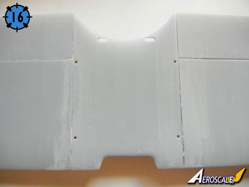
■ Attach the outer upper wings to the wing center section, setting the dihedral at 11mm at the outer tip. Again, see the article "Making Templates" in the "Tips and Reviews" section of the Silver Wings website (www.silverwings.pl) for tips setting the correct dihedral. When dry, my wings had slight gaps on the underside, which were filled by the superglue used to join them (see photo 16).
■ You may want to use a jig for the remaining steps. See the article "Easy Biplane Jig" in the "Tips and Reviews" section of the Silver Wings website (www.silverwings.pl) to create a simple jig for aligning your wings.
■ Once set fit the interplane struts in place, and then test fit the upper wing in position using the interplane struts only. On my example, the center interplane strut was slightly short, but fit fine as I left the wire core long enough to make up for the missing length. However, as with the cabane struts, you may find that the center interplane strut is the correct length and the forward and rear interplane struts are long when fitting a wing with the correct 11mm dihedral.
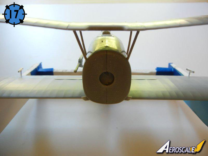
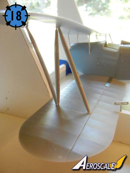
■ Remove the upper wing, dry fit the cabane struts and interplane struts and upper wing (see photos 17 and 18). Trim the wire cores as needed to get the correct strut lengths.
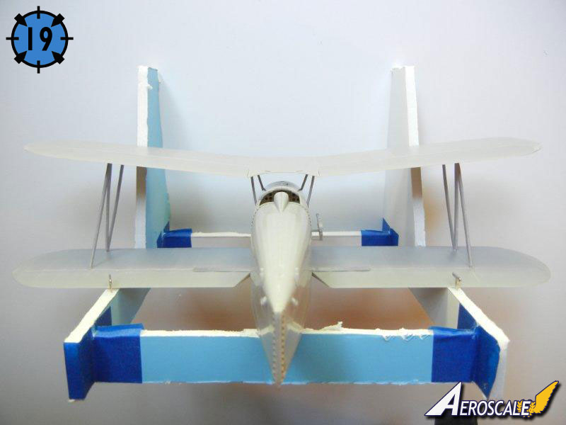
■ Once satisfied with the fit, glue the struts and upper wing in place (see photo 19) using a jig if desired.
■ I recommend waiting to install the control cable guides to the bottom of the wing until final assembly.
Rear Empennage
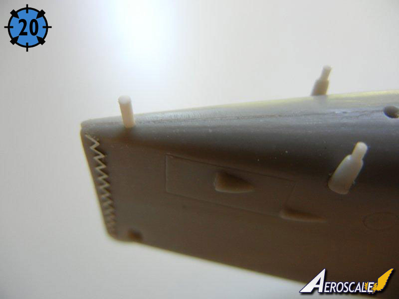
The rear empennage is covered by steps 24 and 26.■ I began by marking the position of the rear support rod and drilling a hole in the fuselage in the appropriate position (see photo 20). This allowed me to use a longer piece of styrene rod, and I could then adjust the rear height as needed to ensure optimum fit.
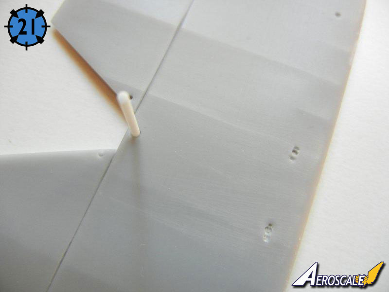
■ I glued the rod into position on the tailplane (and enlarged the fuselage hole fore and aft for easier fitting (see photo 21). I then test fitting the tailplane to the fuselage support rods, which showed that the pre-marked holes in the bottom of the tailplane were in the wrong position. Mark the correct position by placing a small drop of paint on each of the forward support rods, and then placing the tailplane in the correct position. Drill the holes in the appropriate place, which were outboard from the pre-marked holes for my example.
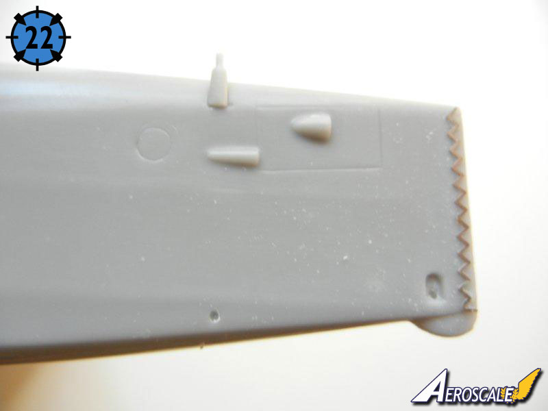
■ Drill out the support brace holes in the bottom of the tailplane and test fit the tailplane to the fuselage. Using the support brace, determine the appropriate forward fuselage attachment position, and mark and drill the attachment hole (there is no pre-sunk hole for this part). See photo 22.
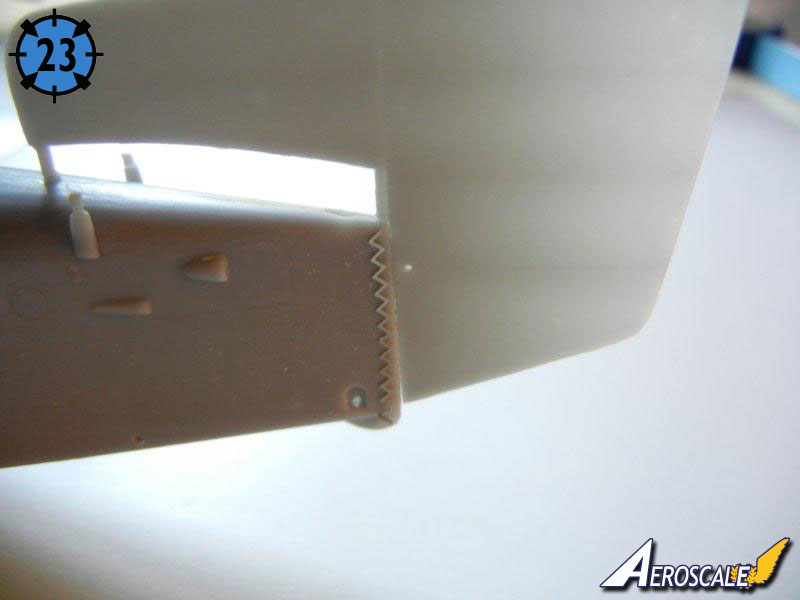
■ Test fit the rudder/vertical stabilizer to the fuselage. I needed to sand the lower portion of the rudder to get a good fit (see photo 23).
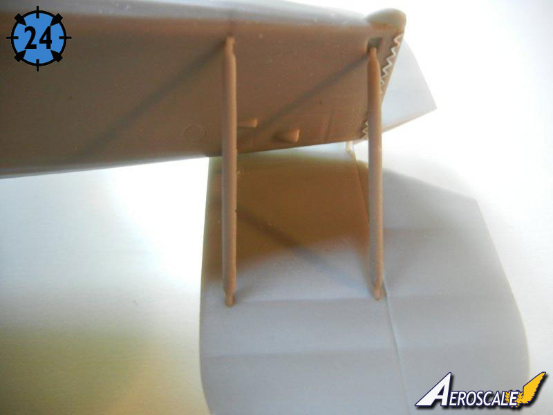
■ Attach the control horns to the bottom of the tailplane and attach the tailplane and support struts into position (see photo 24).
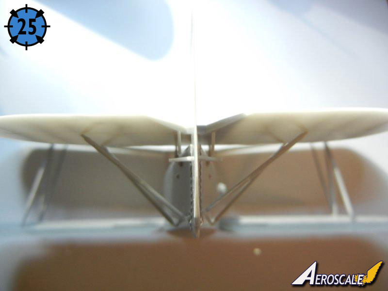
■ Attach the control horns to the rudder/vertical stabilizer into glue into position. Photo 25 shows the completed rear empennage.
About the Author


FROM: GEORGIA, UNITED STATES
I've been modeling on and off for over 40 years. My primary interests are WW1, Interwar and WW2 aircraft, although I do build an occasional WW2 armour kit. I used to build 1/32 kits back in the 80's, but switched to 1/48 in the early 90's when all the nice new kits started showing up. I've sinc...
Comments

Fabulous review Doug and you have just tipped the scales for me in deciding whether or not to buy one of these superb models. The review will be a great reference when it finally gets built.
Off to Paypal we go.....!
Best regards
Gary
FEB 18, 2012 - 05:00 AM


Thank you Doug for this build article, I've been contemplating on this kit and watching Rowan's build. I think my mind is now made up, stop thinking and buy it
FEB 18, 2012 - 04:11 PM
Copyright ©2021 by Doug Nelson. Images also by copyright holder unless otherwise noted. The views and opinions expressed herein are solely the views and opinions of the authors and/or contributors to this Web site and do not necessarily represent the views and/or opinions of AeroScale, KitMaker Network, or Silver Star Enterrpises. Images also by copyright holder unless otherwise noted. Opinions expressed are those of the author(s) and not necessarily those of AeroScale. All rights reserved. Originally published on: 2011-11-12 00:00:00. Unique Reads: 8562

WEB HOSTING BY


Copyright ©2021 AeroScale and Kitmaker Network, a subsidiary of Silver Star Enterprises
All Rights Reserved. Please read our Conditions of Use and Privacy Policy.
All Rights Reserved. Please read our Conditions of Use and Privacy Policy.