

1⁄32Building Silver Wings' Gloster Gladiator
...
Post a Comment
Engine Assembly
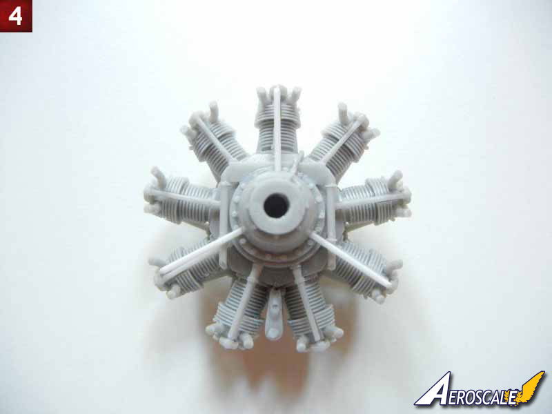
Prior to assembling the engine, you should drill three 1mm (#60 drill bit) holes, one each at the 12:00, 4:00 and 8:00 positions in the gear cover (see photo 4 for location) for the cowl brace (referred to in the instructions as prepare on your own). This brace is actually 3 parts on each brace, one rod from the gear cover to the exhaust collector ring (the front part of the cowl) and two thinner rods from the each side the cylinder head base to the main brace, attaching just below where the main brace meets the exhaust collector. For purposes of this build, I just added the three 1mm rods.Once you have drilled your holes, engine assembly begins with the cylinder heads. Attach each one, making sure it is facing directly forward. You can check your work by putting them up against the exhaust collector ring.
After this, you can attach the pushrods in place; each has a pad on the engine block and the cylinder head to aid in placement. If you are building a Mk1 airframe, you should attach the two downward pointing tubes referred to in the instructions (see photo 4 for location assistance)
Finally, attach the breather tubes to the back of the engine block and cylinder heads.
Interior Subassemblies
- Assemble the throttle as shown in the instructions, the two handles are provided in resin, and just need some careful cleanup.
- Paint the back of the Mk.I or Mk.II instrument film white. On my kit, the Mk.I instrument panel was almost 1mm too wide, so either trim it now, and/or you can thin the cockpit sidewalls where they contact the instrument panel to help ensure a good fit. My references indicate that the panel (either Mk.I or Mk.II) should be black (and it is in many photos), however some preserved airframes show them in a red-brown Bakelite color. Once the white paint is dry, you can attach the film to the back of the appropriate panels. Silver Wings also provides a nice brace for either panel, which makes it much easier to attach to the completed cockpit. The brace should be interior green, and once dry, attach your PE panels in place as appropriate.
- Assemble the ammunition box (two parts to the base plate), but do not attach the chutes until you are ready to close the fuselage in order to get them at the correct angle to meet the gun breeches.
- Assemble the rudder pedals, and attach them to the floorboard. For best results, I bent the PE toe straps around the metal end of a paintbrush, as the PE buckle area does not want to bend as nicely as the rest of it.
- Cleanup and attach the compass pedestal to the floorboard. If you have a decal for a compass, you can apply it after painting for a more realistic look. I left my control stick off until after the cockpit was assembled to make it easier to place the floorboard in the cockpit framing.
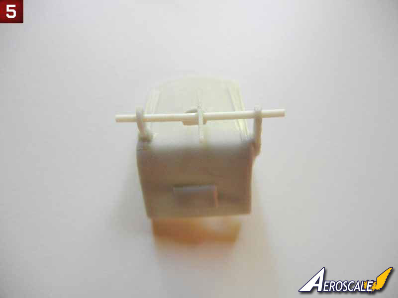
- I found it easier to attach the two brackets to the appropriate sides of the seat, rather than trying to get them in the exact position on the 24mm rod as indicated in the instructions. After the two brackets had set, I put the rod through the appropriate holes, with the bell crank between them. I then centered the bell crank on the rod between the brackets and glued it into position. I did not glue the rod to the seat brackets, as that will allow me to position the seat in the center of the cockpit later (see photo 5). You may also want to attach the seat harness straps to the bottom of the seat before placing it in the fuselage later.
- You can attach the two cylinders and battery to the rear floorboard.
- Photo 6 shows the completed subassemblies (including the cockpit frame and engine)

About the Author


FROM: GEORGIA, UNITED STATES
I've been modeling on and off for over 40 years. My primary interests are WW1, Interwar and WW2 aircraft, although I do build an occasional WW2 armour kit. I used to build 1/32 kits back in the 80's, but switched to 1/48 in the early 90's when all the nice new kits started showing up. I've sinc...
Comments
Copyright ©2021 by AeroScale. Images also by copyright holder unless otherwise noted. The views and opinions expressed herein are solely the views and opinions of the authors and/or contributors to this Web site and do not necessarily represent the views and/or opinions of AeroScale, KitMaker Network, or Silver Star Enterrpises. Images also by copyright holder unless otherwise noted. Opinions expressed are those of the author(s) and not necessarily those of AeroScale. All rights reserved. Originally published on: 2012-01-20 00:00:00. Unique Reads: 9803

WEB HOSTING BY


Copyright ©2021 AeroScale and Kitmaker Network, a subsidiary of Silver Star Enterprises
All Rights Reserved. Please read our Conditions of Use and Privacy Policy.
All Rights Reserved. Please read our Conditions of Use and Privacy Policy.