

1⁄32Building Silver Wings' Gloster Gladiator
...
Post a Comment
Cockpit Assembly
The Gladiator cockpit is primarily interior green with throttle, etc. in black. Assembling the interior for this kit is relatively straight forward, and like other Silver Wings kits, getting the cockpit framing assembled as straight as possible is key. I began building up the interior subassemblies by working on the cockpit framing. For best results, I recommend the following order:- Using square styrene strip, cut two 22mm pieces, one 17mm piece and one 24mm piece.
- Align the two side frames with each other, and glue the center H frame to each side in the position indicated by the instructions.
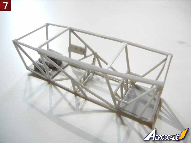
- Immediately glue the V frame to each side in the position indicated by the instructions (note that it should slant back slightly to align with the side frame), followed up the middle-front 22mm styrene piece and the 24mm styrene piece (note that this piece should be fitted immediately behind the sill flange area, otherwise your cockpit will be too wide)
- Double-check your alignment to ensure everything is square (note the cockpit should be narrower at the bottom than the top).
- Next, you can attach the front and rear floor pieces, followed by the two remaining upper styrene pieces (17mm and 22mm). (See photo 7).
- Test fit your completed cockpit frame to the fuselage to ensure it fits properly.
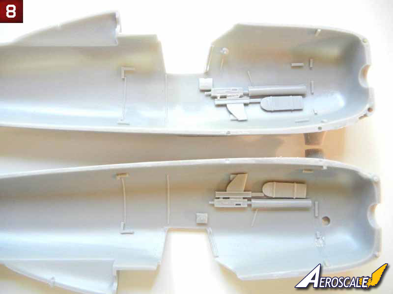
- Now is a good time to attach the required parts to the fuselage side pieces (photo 8) . I elected to omit the front bulkhead as test fitting showed that it was not necessary.
- Next assemble the remaining cockpit components to the frame. Start with the floorboard, which should rest on the V frame in the front, and the tabs on the side frames just above the H frame in the back.
- Attach the bottom seat rod (with the seat) to the cockpit sidewalls, resting it on top of the tabs as indicated. I did not glue the top back part of the seat to the upper frame, allowing it to move forward for the time being (which will be helpful in installing the backplate later).
- Attach the trim wheel and the PE control lever assembly, as well as the throttle and round switch box as indicated by the instructions.
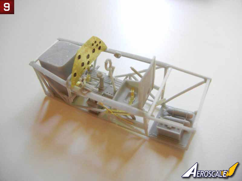
- Attach the fuel tank to the front floor, the ammo bin (dry fit in the fuselage side and use your installed MG's to get the correct fit) and the instrument panel appropriate for your model (see photo 9 and 10).
Fuselage Assembly
Fuselage assembly is straightforward, as one would expect, simply insert the cockpit assembly between the fuselage halves and glue together. There are alignment tabs in the fuselage to help align the cockpit properly. I chose to leave mine "loose" and tacked it in place once the fuselage halves were together.- Once your fuselage glue is set, you can clean up the seams.
- Moving your seat back forward (pivoting on the lower rod), insert the rear backplate, taking care to center it within the fuselage. Once the fit is correct, you can glue it into position, followed by the seat back once the backplate is set.
- If you are going to attach either of your side doors in the closed position, do so now. If either will be open, they can be added later.
- Next, attach the seat harness tray, and the upper seat harness straps (the tip of the harness should be just through the slot in the backplate), then attach the other side strap, and final cap with the small PE attachment plate. Finally, attach the two tensioning springs (PE7) to either side. Mine were a little long, so I trimmed them to fit.
- I then attached the gun sight frame pieces, followed by the gun sight with the appropriate film.
- Attach the front windscreen and rear canopy at this point being sure to center them on the fuselage. If you plan to have your main canopy closed, you should use it to get the proper position of the windscreen and rear canopy to optimize the overall canopy fit.
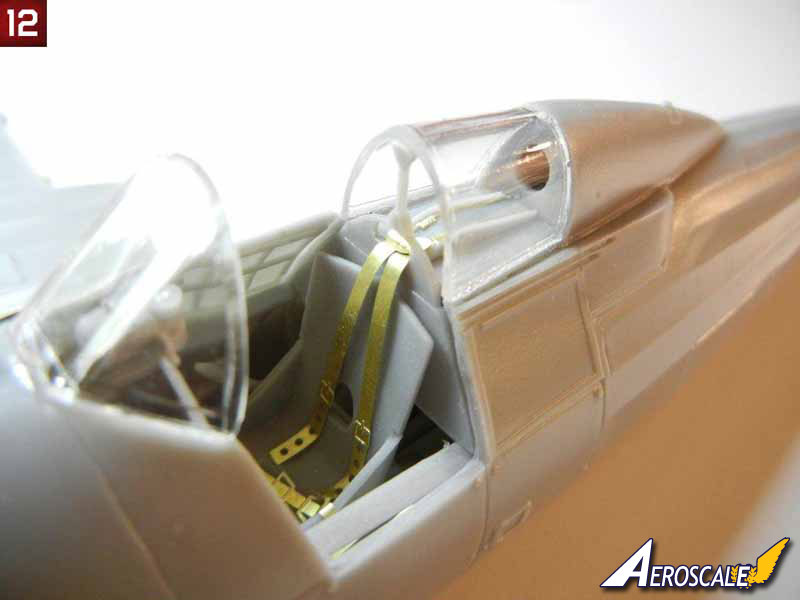
- Once dry, test fit the brace that attaches between the backplate and top of the rear canopy. I needed to sand mine slightly, and then attached it in position. (see photo 11 and 12).
- I then took the opportunity to drill out the cabane strut attachment points, after making a drill guide template (see photo 13).
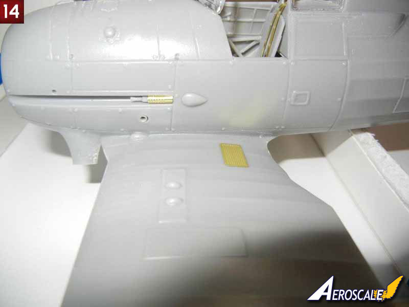
- Assemble the fuselage MG's and attach as indicated in the instructions. I believe that the longer MG barrels should go on the fuselage, but can't be sure (I used the shorter ones on the fuselage for this build - but the longer ones look too long on the wing). Bend parts PE14 into the correct curved shape (I used the handle of a paintbrush, and then bent the inner rear parts in past the vertical for the best fit) and attach as indicated (photo 14). Note that they highest part of PE14 should be just about flush with the fuselage.
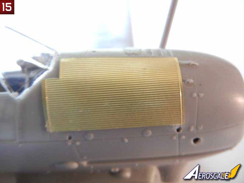
- Bend the radiator mat to fit the curve of the fuselage (I rolled an Xacto handle on mine to get the correct shape). Note that there should be a slight space between the mat and the fuselage. the kit has 4 raised attachment stubs molded to the fuselage. Test fitting the mat showed that these left what I felt was too large of a gap for my tastes, so they were sanded down slightly. I then glued the radiator mat into position. Attach the small rod (vent?) to the hole in the top of the fuselage as indicated in the instructions (see photo 15) .
Cowling Assembly
You may want to pre-paint the interiors of the cowls and exhaust collector ring, and touch up as necessary after assembly. After studying the parts, I came up with the following assembly sequence to get the cowl together:- Attach the lower cowl piece to the exhaust collector ring (the front of the cowl), taking care to get it aligned properly (see photo 16).
- Once dry, test fit the completed engine to the exhaust collector ring. You will likely have to apply some pressure to get a good fit - be careful not to press too hard or you may break some of the cylinder exhaust tubes (ask me how I know this)! Sand any cylinder exhaust pipes that do not fit properly.
- Once you are satisfied with the fit (and the engine is square to the exhaust collector ring), glue the engine to the exhaust collector ring using the exhaust tubes on the cylinders. Note that these pipes were welded to the exhaust collector ring on the real aircraft, so you do not need a perfect attachment, some superglue gel around the pipe to represent the weld is fine :)
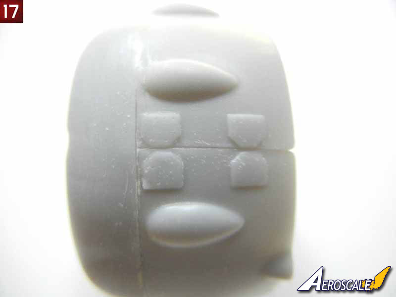
- When dry, you can test fit the upper cowl piece. Mine was too big, so I sanded down each side of the cowl-to-cowl attachment surfaces to the raised bracket points (see photo 17).
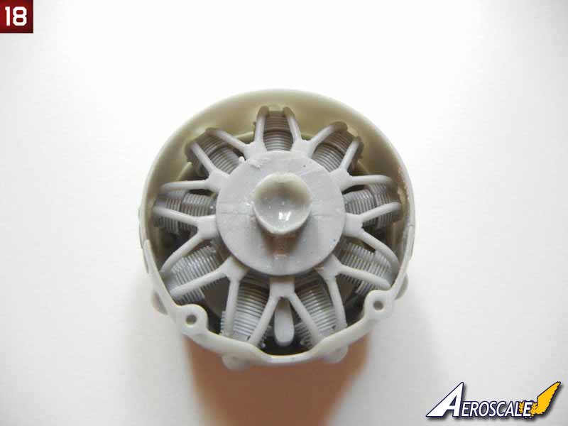
- I then glued one side of the cowl-to-cowl mating surface, let set and then glued the opposite side. I then glued the remaining cowl to exhaust collector ring surface (see photo 18 and 19).
- Attach straps PE16 to each side of the cowl to complete the assembly.
- If desired, you can now paint your cowling and set the completed assembly aside until final assembly


About the Author


FROM: GEORGIA, UNITED STATES
I've been modeling on and off for over 40 years. My primary interests are WW1, Interwar and WW2 aircraft, although I do build an occasional WW2 armour kit. I used to build 1/32 kits back in the 80's, but switched to 1/48 in the early 90's when all the nice new kits started showing up. I've sinc...
Comments
Copyright ©2021 by AeroScale. Images also by copyright holder unless otherwise noted. The views and opinions expressed herein are solely the views and opinions of the authors and/or contributors to this Web site and do not necessarily represent the views and/or opinions of AeroScale, KitMaker Network, or Silver Star Enterrpises. Images also by copyright holder unless otherwise noted. Opinions expressed are those of the author(s) and not necessarily those of AeroScale. All rights reserved. Originally published on: 2012-01-20 00:00:00. Unique Reads: 9803

WEB HOSTING BY


Copyright ©2021 AeroScale and Kitmaker Network, a subsidiary of Silver Star Enterprises
All Rights Reserved. Please read our Conditions of Use and Privacy Policy.
All Rights Reserved. Please read our Conditions of Use and Privacy Policy.