

1⁄32Building Silver Wings' Gloster Gladiator
...
Post a Comment
Lower wings
- ill out the wing strut attachment points using a drilling template (check the "Tips and How To's" section of the Silver Wings website (www.silverwings.pl) for an article on making and using drilling templates).
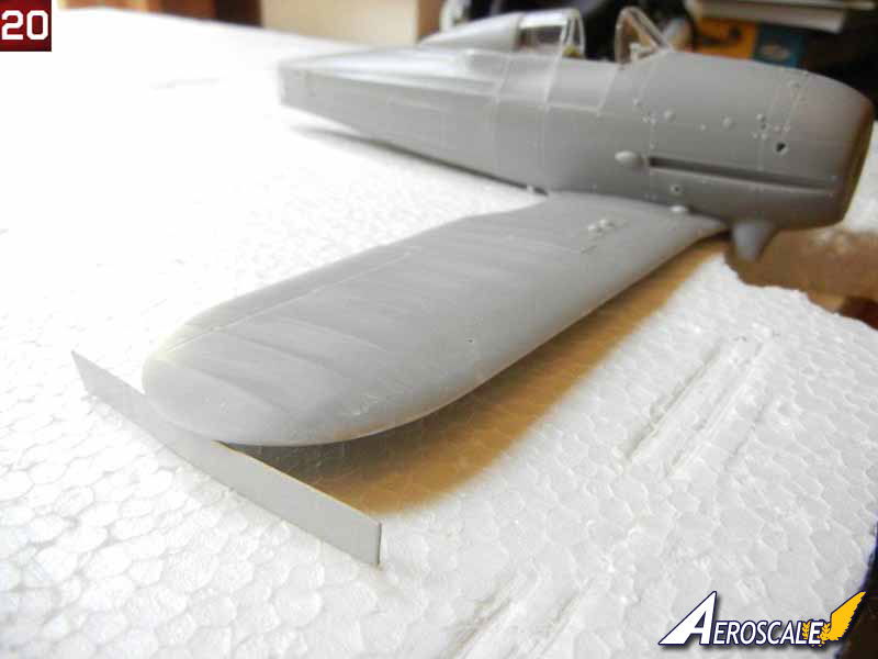
- I placed my model on a piece of styrofoam and gouged out slot for the MG's on the bottom of each wing. Once I had a level surface, I glued the wings to the fuselage, using a 6mm spacer at the tips as indicated in the instructions to achieve the correct dihedral. (see photo 20).
- Attach the anti-skid plates (PE15) to each wing as indicated.
- You can attach the underwing MG barrels, or wait until after painting.
Upper wings
- Before assembling the upper wings, I drilled out the cabane strut holes, and wing strut holes using drilling templates.
- I test fit the wing center section and cabane struts to the fuselage to ensure a good fit (see photo 21).
- Once satisfied with the fit, remove the wing center section and attach the outer wing sections. Place the wing parts on a flat surface, and glue the wings into position, using a 6mm spacer at the tips as indicated in the instructions to achieve the correct dihedral.
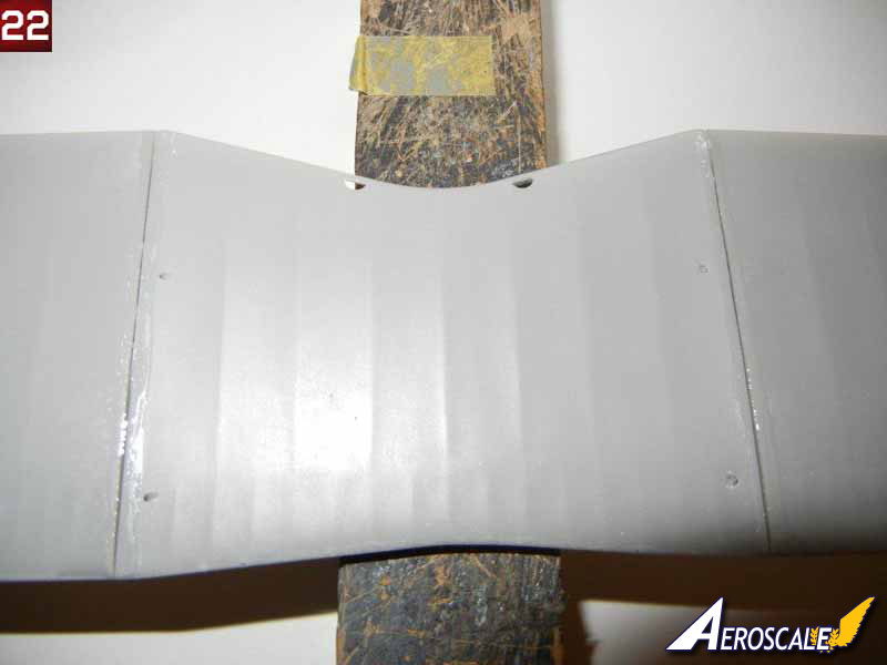
- I had some slight gaps on the bottom of the wing where the center and outer wing parts meet. I filled these with superglue (see photo 22) and sanded smooth once dry.
- I then made a homemade jig (see the Tips & How To's section of the Silver Wings site for an article on making your own simple jig) and began the process of attaching the upper wings.
- I sorted out the interplane struts, and found that one pair was ever so slightly longer than the other. As one of the longer pair has a round bump on the front, and the instructions indicate this one goes on the starboard side front, I was able to then sort out which struts went where (the ever so slightly longer ones in front, and the others in the rear). I did note in test fitting that the curve of the resin part of the interplane struts do not match precisely the curve of the wing surfaces (see photo 23).
- Fit each strut to its appropriate position on each mating surface, and trim the brass rod parts to ensure a good fit.
- When ready, mix up some epoxy and start attaching the struts to the fuselage and lower wings in their appropriate positions. When tacky, place the upper wing in position and secure it using your favorite jig to ensure proper alignment.
- Once the epoxy is dry, you can remove the upper wing and clean up any that oozed out where it should not be. At this point, you will want to use your favorite filler as necessary to get a perfect attachment point of the struts to their fuselage and lower wings.
- Once complete, mix up some more epoxy and attach the upper wing, securing it with your favorite jig (see photo 24).
Rear Empennage
The rear empennage for this kit is very straightforward. The kit does provide the rear bell crank for the elevators, which are barely visible on the finished kit, so you should decide if you want to attach any control cables to them. You can also complete this step at any time after you have glued the fuselage together, depending on what you think will be easiest for you and the painting scheme you have chosen.- Start by attaching the vertical stabilizer to the fuselage.
- Then attach the horizontal stabilizers, ensuring that everything is aligned properly. I noted a tight fit on the port side stabilizer, so I opened the holes slightly to aid in a good fit. Oddly, when I was attaching the horizontal stabilizers, I noticed that if I attached them one way, there was an angle across the backside of them, whereas the other way, the backside was straight. So, be sure to check before gluing that everything is straight.
- Now, attach the bell crank assembly to one of the elevators. Test fit to be sure that the bell crank will be more or less centered when looking at them from the slot in the rear. Then test fit to the other elevator, and trim as necessary to get a good fit while keeping them in the proper position.
- Attach the control horns to each side of the rudder as indicated in the instructions, and then attach the rudder into position as desired (see photo 26).
Final Assembly
Now we are on the home stretch, and we have a model that looks pretty much like a Gladiator :) You should decide at what point you want to paint (and rig if desired) your model, and stop and do so when you have assembled the necessary parts. Now let's get those final bits attached!- I started by test fitting the air intake tubes into the holes provided in the front of the fuselage. When I attempted to fit them with the engine/cowl assembly in place, I noticed the holes needed to be relocated, so I noted the correct position and drilled new mounting holes. Photo 27 shows one hole drilled in the proper position (lower and to the outside) on the left, while the two existing holes can be seen as well.
- Next, I glued the main gear legs in position (be sure to select the proper legs for your choice of skis or wheels). I drilled out the mounting hole in the fuselage to make it deeper, and did not trim any of the brass rod to provide maximum strength. You should trim the brass rod where the wheel or skis will attach to ensure a proper fit.
- I attached the step using the three holes indicated in the port-side bottom of the fuselage, and attached the pitot tube to the port side front strut as indicated in the instructions. If your model was equipped with a radio, you can attach the antennae mounting pins on the rudder and upper wings.
- I trimmed 2mm off the attachment point of the carb intake, and glued it in position in the square hole provided in the bottom of the fuselage.
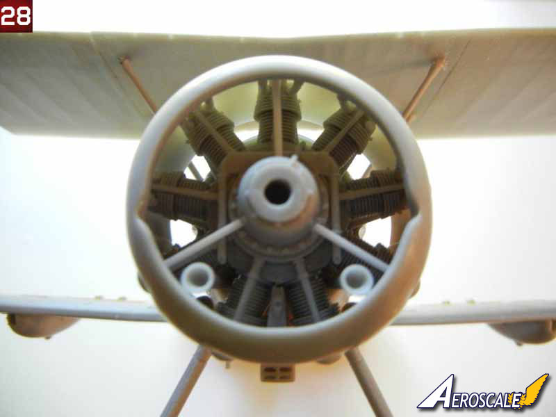
- Now we can attach the engine/cowl assembly to the fuselage. Once positioned, I then attached the two air intake tubes (see photo 28).
- Now we can attach the exhaust pipes. There is supposed to be a mounting pin towards the rear where the bracket is on the pipes. As this is missing, I needed to make my own. I drilled out the two faint holes in the fuselage at the rear of the main gear struts with a 1mm drill, and inserted two small pieces of the same size styrene rod. I then test fit the exhaust pipes to the cowl and sanded slightly until they were in the correct position (see photo 29).
- You can attach your main wheels and tail wheel (or skis) as indicated in the instructions. Note that the wheels should be attached so that the spot where the remains of the pour bock was is at the bottom to ensure the inside detail is in the correct position.
- Attach the wing MG's in place, and attach the appropriate propeller for your model.
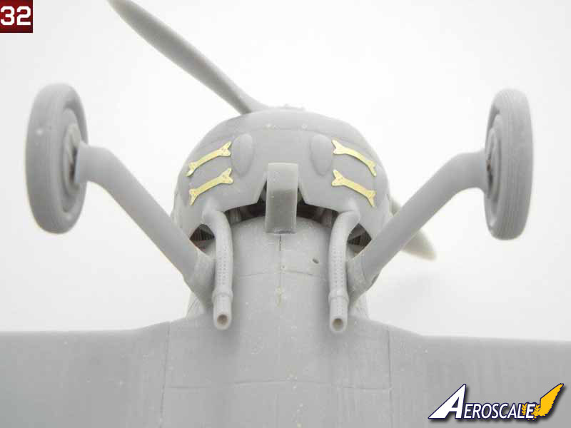
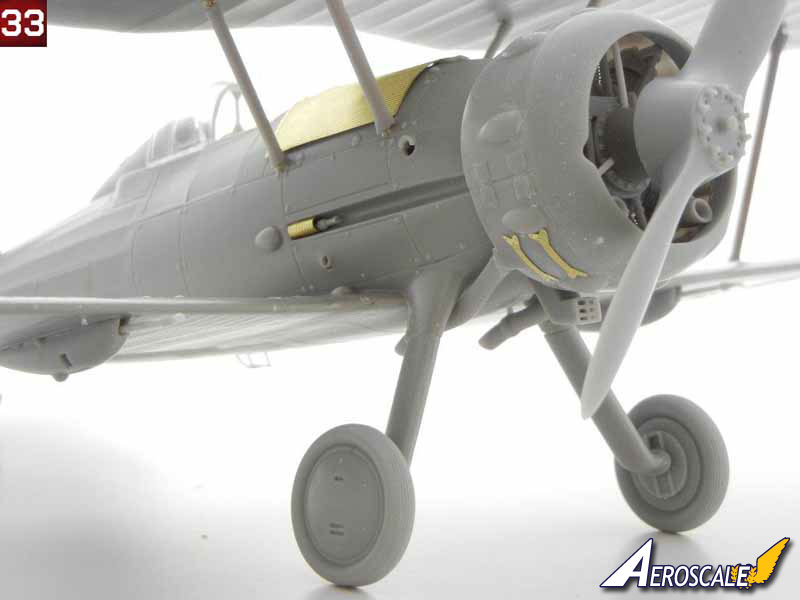
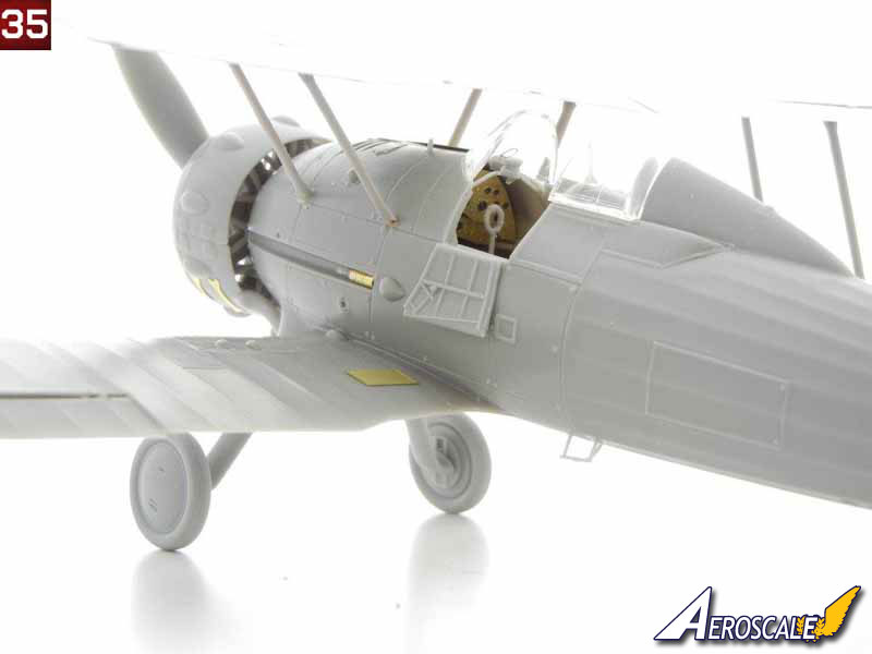
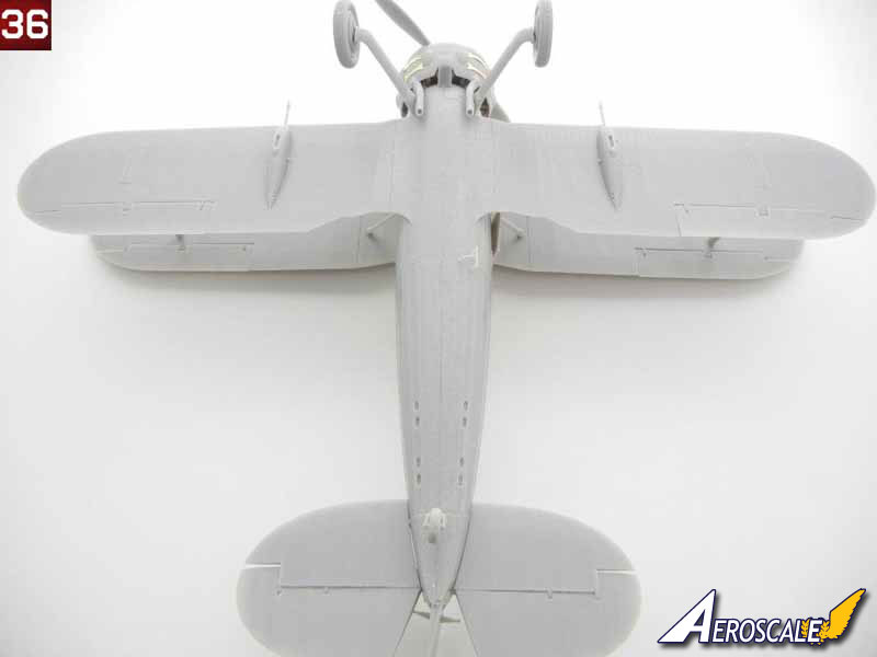
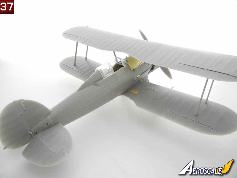
Congratulations on your newly finished model! Photos 30 ~ 37 are of the completed model.


About the Author


FROM: GEORGIA, UNITED STATES
I've been modeling on and off for over 40 years. My primary interests are WW1, Interwar and WW2 aircraft, although I do build an occasional WW2 armour kit. I used to build 1/32 kits back in the 80's, but switched to 1/48 in the early 90's when all the nice new kits started showing up. I've sinc...
Comments
Copyright ©2021 by AeroScale. Images also by copyright holder unless otherwise noted. The views and opinions expressed herein are solely the views and opinions of the authors and/or contributors to this Web site and do not necessarily represent the views and/or opinions of AeroScale, KitMaker Network, or Silver Star Enterrpises. Images also by copyright holder unless otherwise noted. Opinions expressed are those of the author(s) and not necessarily those of AeroScale. All rights reserved. Originally published on: 2012-01-20 00:00:00. Unique Reads: 9803

WEB HOSTING BY


Copyright ©2021 AeroScale and Kitmaker Network, a subsidiary of Silver Star Enterprises
All Rights Reserved. Please read our Conditions of Use and Privacy Policy.
All Rights Reserved. Please read our Conditions of Use and Privacy Policy.