

1⁄32Building the Silver Wings Siskin
...
Post a Comment
Parts Cleanup
As with other Silver Wings kits, parts cleanup is fairly simple, and due to the soft resin they use for their kit, a sprue cutter can even be used to snip most parts from their pour stubs. After that, a few scrapes with the Xacto knife and/or sanding stick and the part is ready for use.With these kits, since there are no part numbers to worry about, I like to clean up all the parts and then begin the build. Any parts can be painted as appropriate after cleanup and before assembly as well. A few things to note when preparing your kit parts for use:
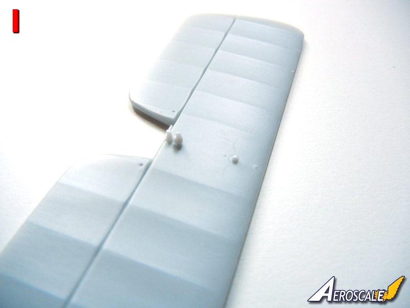
Use caution in removing the tailplane from the clear plastic bag. It should have 3 pins attached to the bottom (see Photo 1), however 2 were broken off on my kit, but were still in the bag, so I was able to reattach them.
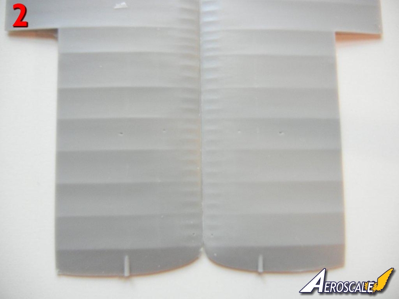
The wings have excess resin rods on the upper tips (see Photo 2), these must be removed as the outer wing should be smooth.
Check your fuselage framing for any breaks before you remove the pour blocks. You should repair any breaks with superglue before removing the pour blocks If you intend to use the kit provided cockpit frame cross brace tubes, be sure to measure them before you remove them from the pour stubs as I found I had to trim carefully in order to not end up with tubes that were too short.
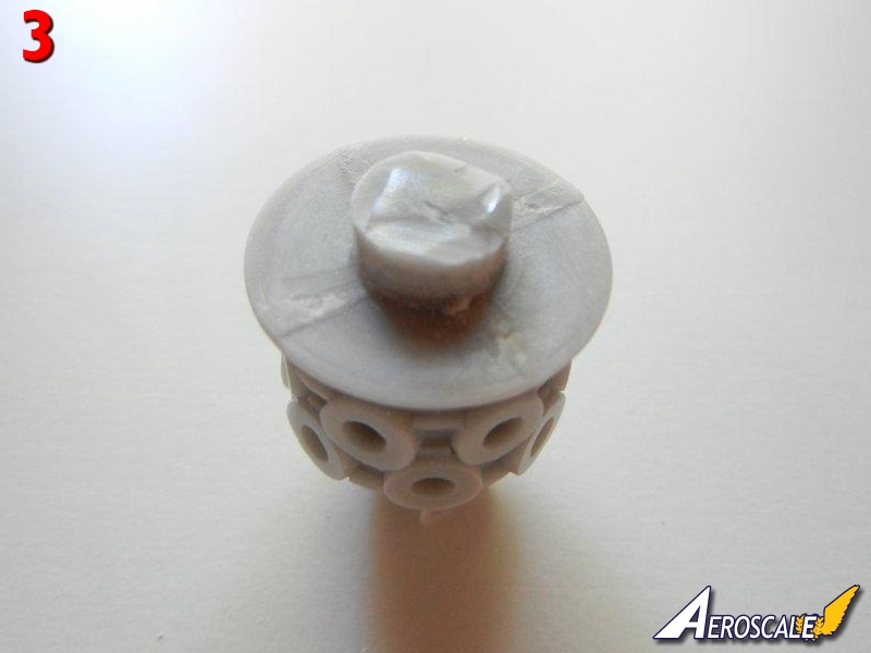
The engine block has a pour block on the backside, and you should only remove the fins, leaving the center round part as this will be needed to attach the engine/cowl assembly to the fuselage. (Photo 3) Some of the engine cylinders may have some slight seams on the sides that require cleanup, however any that you "miss" during cleanup will likely not be visible on the finished model without searching really hard for them.
Test fit your propeller to the engine block and enlarge the hole as necessary to achieve a good fit. The seat has a square that sits proud of the seat itself on the underside. This is used for positioning the seat on the support framing and should not be removed. The remaining parts on the bottom of the seat should be removed (although they may look like seat mounting brackets).
Interior Subassemblies
There are a few items that can be assembled before installation in the cockpit, as indicated on page 2 of the instructions. I'll review them here:Center Floor Brace (control column/rudder pedals/compass): I used a paintbrush handle to bend the PE rudder straps. Attach the completed rudder pedals to the center floor brace as it will be easier to do so now than after the floor brace is installed in the cockpit frame. Attach the compass as indicated in the instructions, being sure to get it at the proper angle and install the film compass dial after painting. I tried to use my punch set to punch out the compass from the clear film, but the film is somewhat brittle and the printing got damaged doing it that way. The control column should fit onto the flat area in the center rod of the center floor brace as indicated in the instructions with any difficulties. I recommend waiting until after you have the rest of the interior installed before permanently attaching the control column to avoid breaking it. Be sure to install it so that the triggers are on the side facing the seat.
Instrument Panel: Cut out the instrument backing from the clear film and paint the back white, and install in in position on the PE instrument panel. After assembly, you'll need to paint the back of the panel black as some of it may be seen through the gun troughs if you look hard enough. Also don't forget to cut out and install the "map" provided before installation - I did and it was a a little difficult to get it into position later.
I recommend leaving the barrels off the machine guns, and installing them after you've assembled and painted the fuselage. This will make it easier to get them into the correct position, and if they are not centered on the breech, it will not be visible. Accordingly, attach the PE parts as indicated to each machine gun breech.
Wait to assemble the oil cooler until after you have the fuselage completed and painted. You'll need to attach the two posts provided making sure that the attachment bracket detail is oriented the correct way before assembling the PE leaves.
I recommend leaving the PE propeller blades off the three generators until after they have been test fit to the model.
I also recommend leaving the shell ejection chutes off the shell ejection ports until they have been installed in the fuselage, and the cockpit with machine guns test fit to ensure proper placement. Although not shown on page 2, you should paint the seat and install the PE seatbelts prior to installation (you'll note it magically appears with seatbelts installed on page 3).
Cockpit Assembly
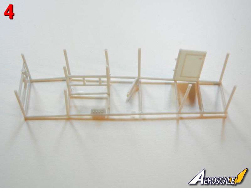
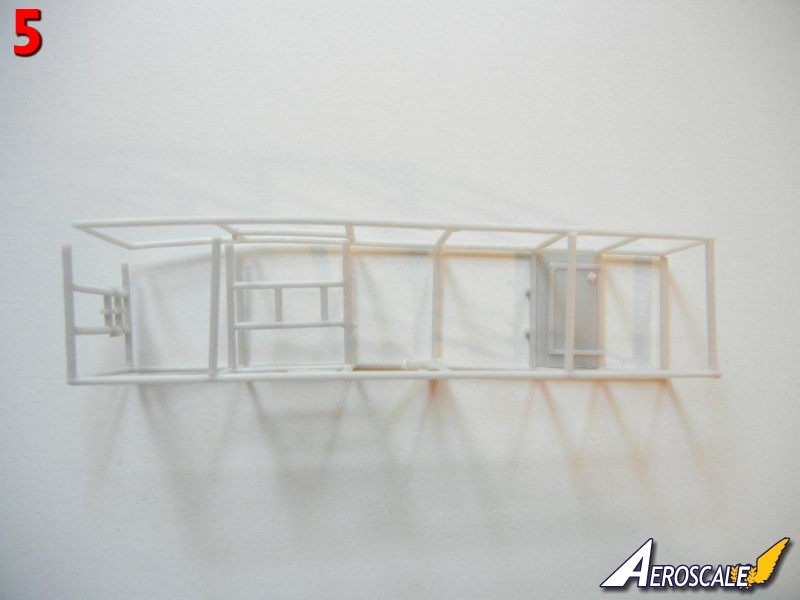
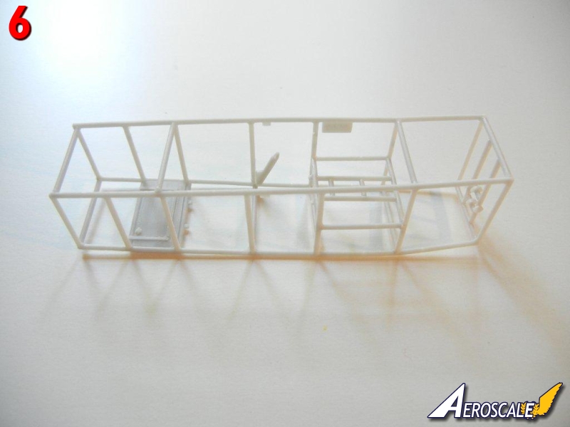
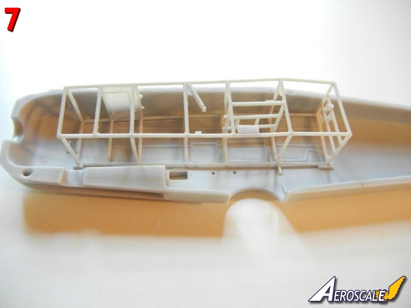
Cockpit assembly starts on page 3 of the instructions. If you've built any other Silver Wings kits, assembly should be familiar to you. I started my assembly by cutting the provided resin cross-braces to the appropriate lengths as indicated (you may find it easier to use plastic or metal rod). I then attached the rods, front floorboard and "cat's cradle" to one side of the framing (see Photo 4). I then attached the opposite side framing piece, starting at one end and moving towards the other to ensure the best alignment (see Photo 5/6). Once complete, test fit the frame into the fuselage to be sure everything is lined up properly (see Photo 7).Next, attach the heel boards on either side of where the center floor brace will attach Once complete, attach the center floor brace assembly (with rudder pedals and compass) - tabs are provided on both attachment frames to help with alignment. I then attached the seat to the center of the "cat's cradle" and the cylindrical oil(?) tank, trim wheel and throttle control as indicated in the instructions.
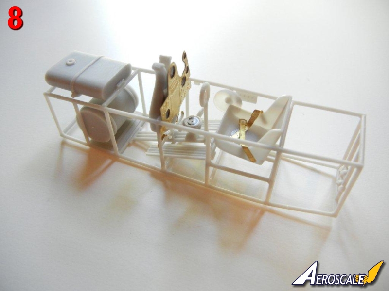
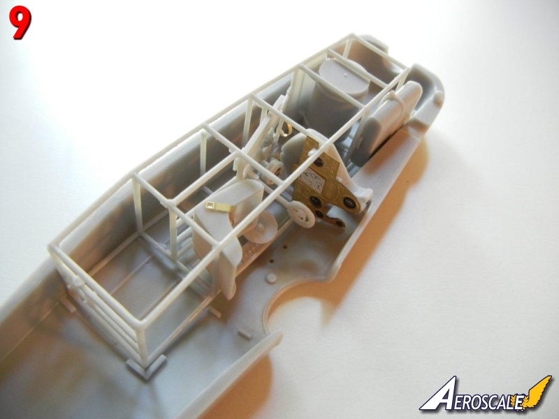
Attach the fuel tank and the ammo magazine in position as shown (see Photo 8) and test fit the assembly in the fuselage (Photo 9).
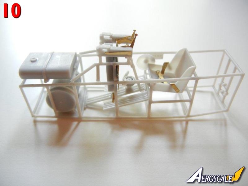
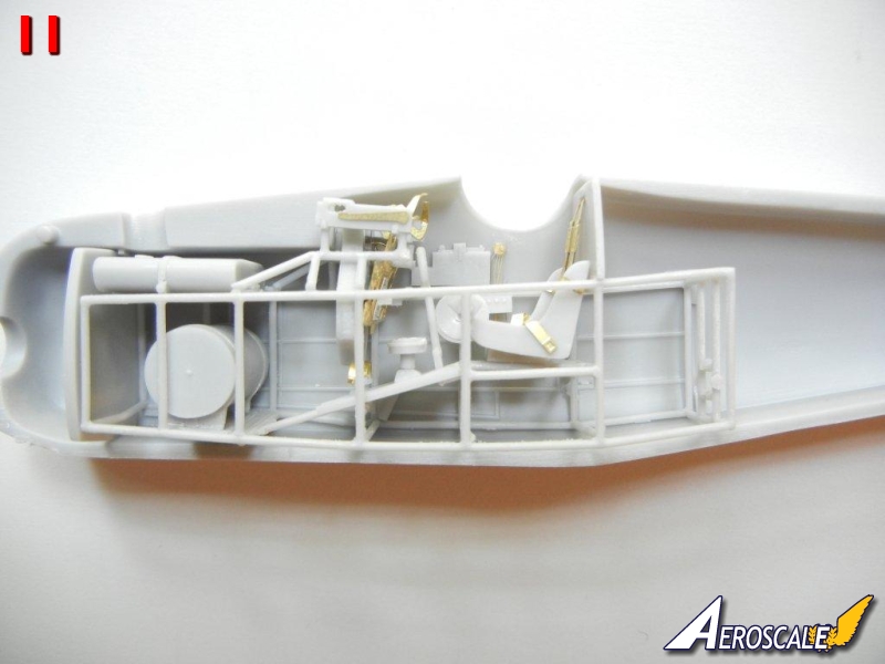
Now comes the only part that might be challenging, which is attaching the framing that holds the machine guns. First, attach the machine gun breech to the framing part, putting the breech as far towards what will be the rear as possible. I attached them to the position that seems to be indicated in the instructions (see Photo 10) and checked to see that they were approximately 9.5mm apart. Even with this, I found that the breeches of the machine guns were pushed backwards by the area of the fuselage where the gun barrel slots are (see Photo 11). I ended up trimming my fuselage and gun breeches a little in order to improve the fit. You may want to place your framing further towards the rear, so that the first vertical leg is right at the back of the ammo magazine for a better fit. I also had to bend the charging handles down quite a bit so that they cleared the top of the fuselage.
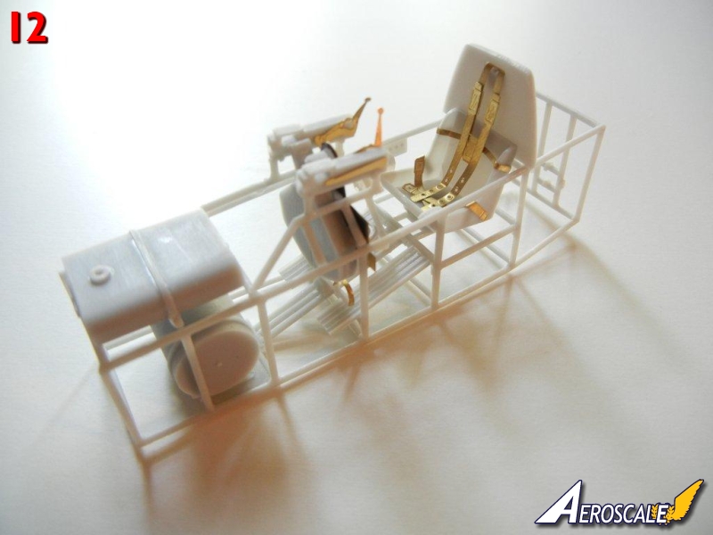
I folded the shoulder harness as indicated, and attached the backplate on top of the cockpit framework behind the seat as indicated on page 4 of the instructions, and when it was dry, I attached the shoulder harness in the slot (see Photo 12).
About the Author


FROM: GEORGIA, UNITED STATES
I've been modeling on and off for over 40 years. My primary interests are WW1, Interwar and WW2 aircraft, although I do build an occasional WW2 armour kit. I used to build 1/32 kits back in the 80's, but switched to 1/48 in the early 90's when all the nice new kits started showing up. I've sinc...
Comments
Copyright ©2021 by Doug Nelson. Images also by copyright holder unless otherwise noted. The views and opinions expressed herein are solely the views and opinions of the authors and/or contributors to this Web site and do not necessarily represent the views and/or opinions of AeroScale, KitMaker Network, or Silver Star Enterrpises. Images also by copyright holder unless otherwise noted. Opinions expressed are those of the author(s) and not necessarily those of AeroScale. All rights reserved. Originally published on: 2012-08-18 00:00:00. Unique Reads: 8122

WEB HOSTING BY


Copyright ©2021 AeroScale and Kitmaker Network, a subsidiary of Silver Star Enterprises
All Rights Reserved. Please read our Conditions of Use and Privacy Policy.
All Rights Reserved. Please read our Conditions of Use and Privacy Policy.