

1⁄32Building the Silver Wings Siskin
...
Post a Comment
Upper wings and wing attachment
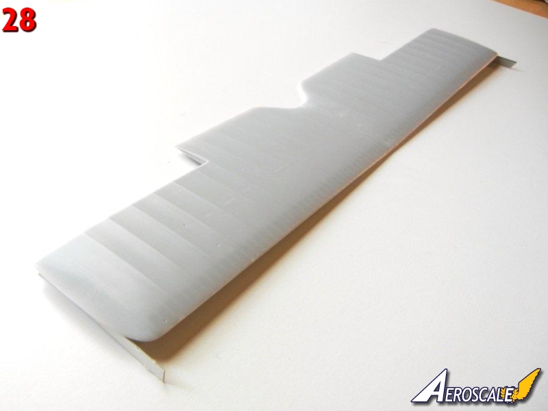
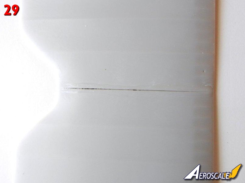
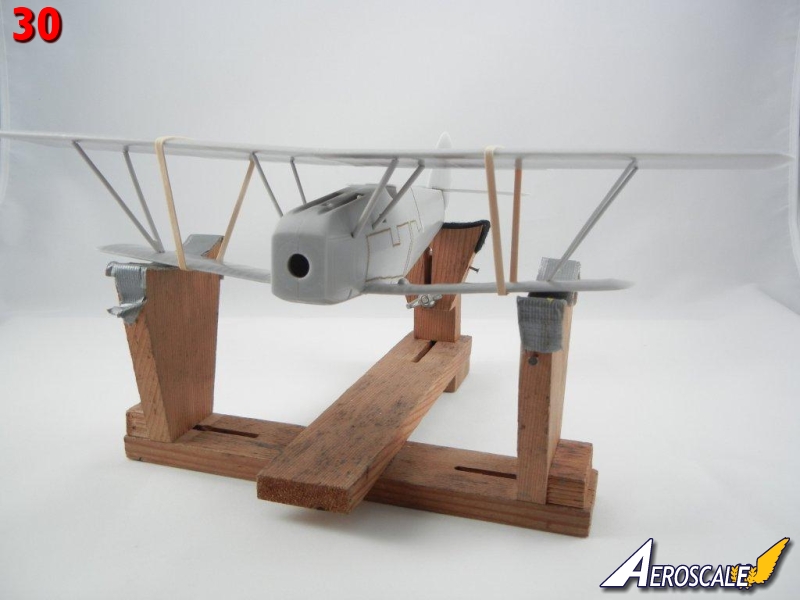
The upper wings should have 5mm of dihedral according to the instructions (page 6). Although not shown, you will need to join both upper wing halves together. As with the lower wings, I recommend you drill out the appropriate holes for the struts and use the full metal rod if possible to provide extra strength.Again, begin by drilling out the holes for the struts (and rigging if desired) in the fuselage and upper wings (see page 8 for proper strut placement). Test fit the upper wings together and check the dihedral, adjust as necessary (the metal rod can be bent of necessary). When satisfied, glue together (photo 28). I had a slight seam on the upper surface of the join, which was filled with the superglue used to join the wing halves (photo 29). I test fitted the struts to the upper wing and adjusted the length of the metal rod to achieve the optimal fit. I then test fit the upper wing to the rest of the aircraft, to see if there were any issues I would need to address. Fortunately, there were none, and the fit seemed quite good. Photo 30 shows the test fit (note rubber bands holding everything together).
At this point, you will want to attach the small parts to the upper fuselage and paint/decal your model taking advantage of the ease-of-access before permanently attaching the upper wing once everything is in place.
When you are ready to attach the upper wing, again test fit to make sure all the struts are in the correct position for optimal fit, and make any final adjustments.
You may want to use a jig for the remaining steps. See the article "Easy Biplane Jig" in the "Tips and Reviews" section of the Silver Wings website (www.silverwings.pl) to create a simple jig for aligning your wings.
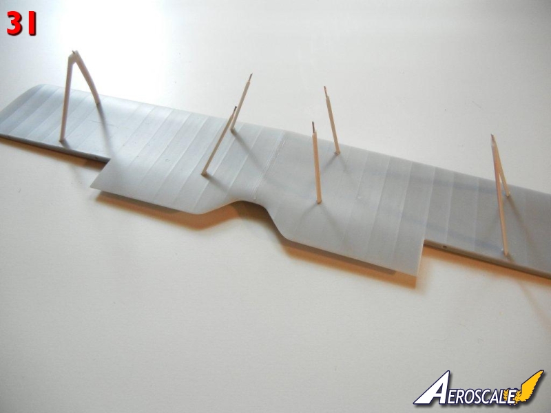
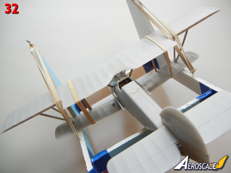
This time, I decided to attach the interplane and cabane struts to the bottom of the upper wing using slow setting superglue (Photo 31).
I then immediately used the same slow setting superglue to begin attaching the struts to the main assembly, starting with the cabane struts, and finishing with the interplane struts. I then placed the model into the jig to make sure the wings were properly aligned (Photo 32).
Main Landing Gear
The main gear appears complex, but it is fairly easy to attach correctly. For the purposes of this Build Guide, we'll separate the main gear assembly into two parts, the rear support structure, and the main axel.Test fit the two "V" shaped support structure braces into the slots on the bottom of the fuselage, as indicated on page 9 of the instructions. You will need to trim the resin "pins" on the end of the support legs to achieve the optimal fit. Test fit the cross brace, and trim the brass rod so that only a slight amount shows when inserted into the holes in the "V" shaped support struts (this slight amount of brass rod is where we will attach the braces that connect the support structure to the main axel).
Attach the support structure "V" braces to the fuselage, trapping the cross brace between them. Test fit the main axel legs (with the shock covers on them) to the fuselage as indicated on page 9, placing the main axel between them, using the mounting flange on the main axel to ensure proper positioning.
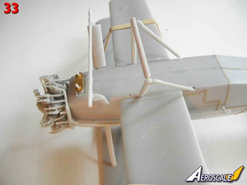
Attach the main axel legs using slow setting superglue or epoxy, and attach the main axel to them (photo 33 shows the assembly thus far).
Attach the small connecting rods to the rear support structure, using the space with the brass rod showing on the cross brace.
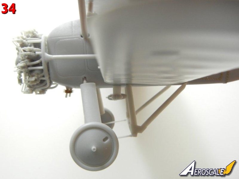
Pull back the main gear to meet the connecting rods and glue in place. Photo 34 shows the rearward angle of the completed gear for reference.
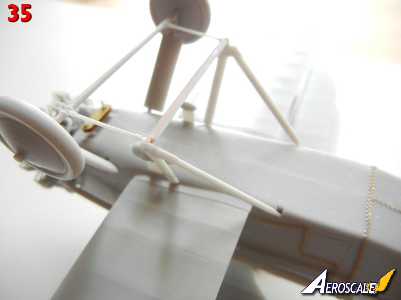
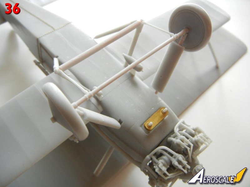
Attach the main wheels when dry. Photos 35 and 36 show the completed landing gear assembly.
Final Assembly
Page 10 provides the rigging and control cable installation guides.Attach the engine, and long exhaust pipes, as well as the PE structure that attaches to the top cylinder.
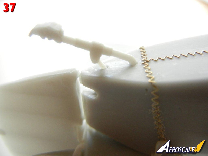
Attach the tail skid to the bottom of the rear fuselage using the holes provided. On my example, the rear attachment rod was missing (and on my other two kits), so I made one from a piece of plastic rod (see Photo 37).
Attach the control cable support guides into position on the ailerons of the top wings. If you are going to attach the control cables, Silver Wings has molded pre-sunk holes for the cables in the wings and ailerons.
Attach the lights on the wing tips and center of the wing.
If your model was equipped with a radio, make two aerial posts out of .020 plastic rod, and attach to the upper wing in the holes provided (drill out for a better fit). Also attach the aerial post on the fuselage behind the cockpit. If your model was not equipped with a radio, you'll want to fill the holes. Finally, attach the pitot to the forward starboard interplane strut.
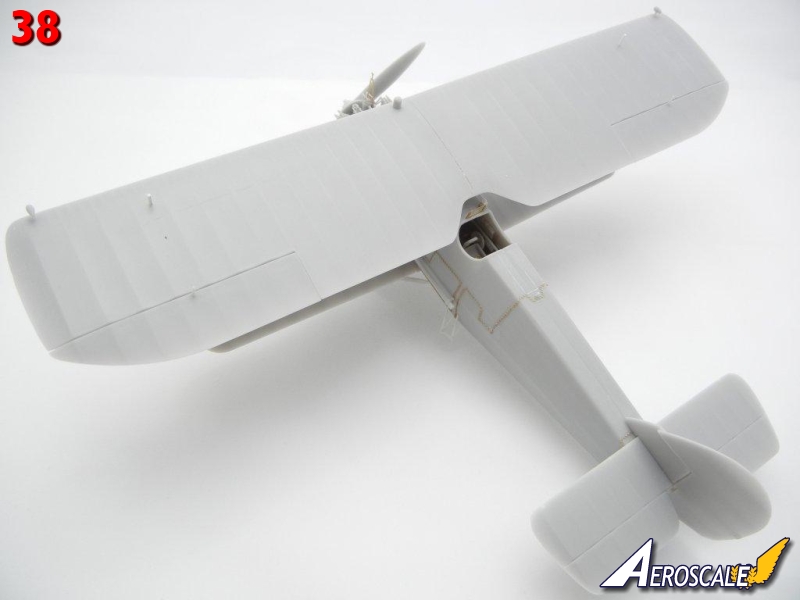
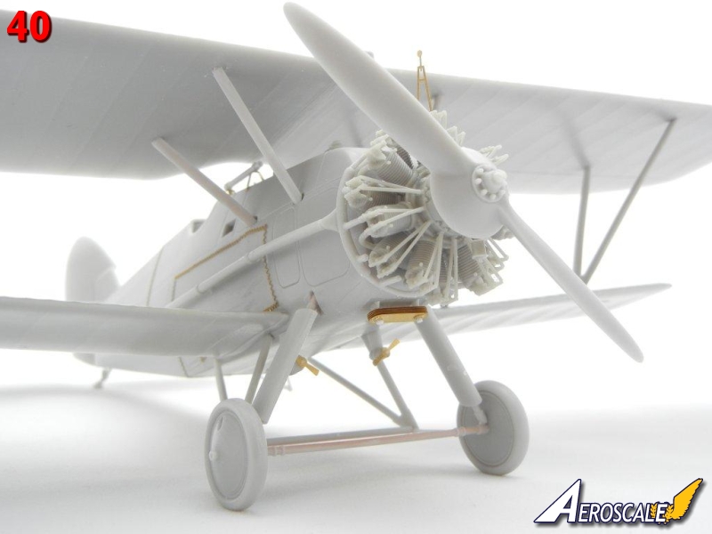
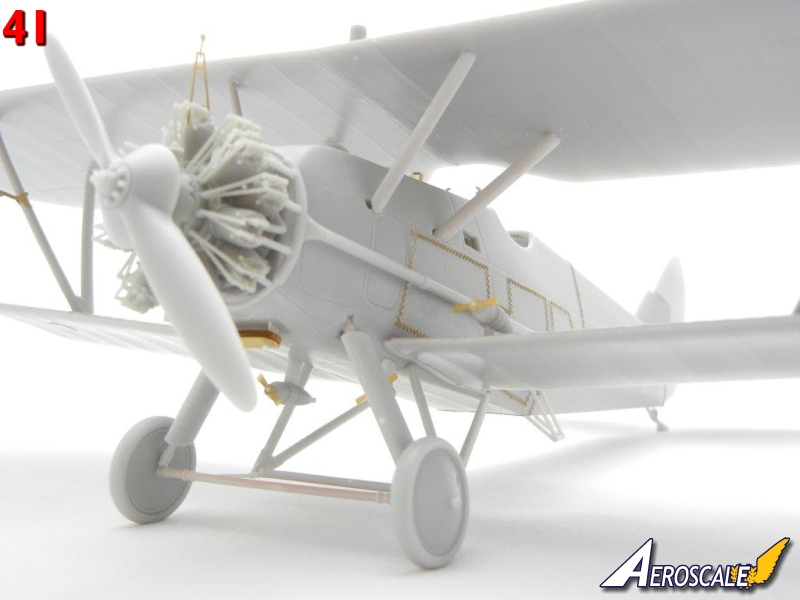
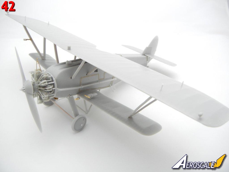
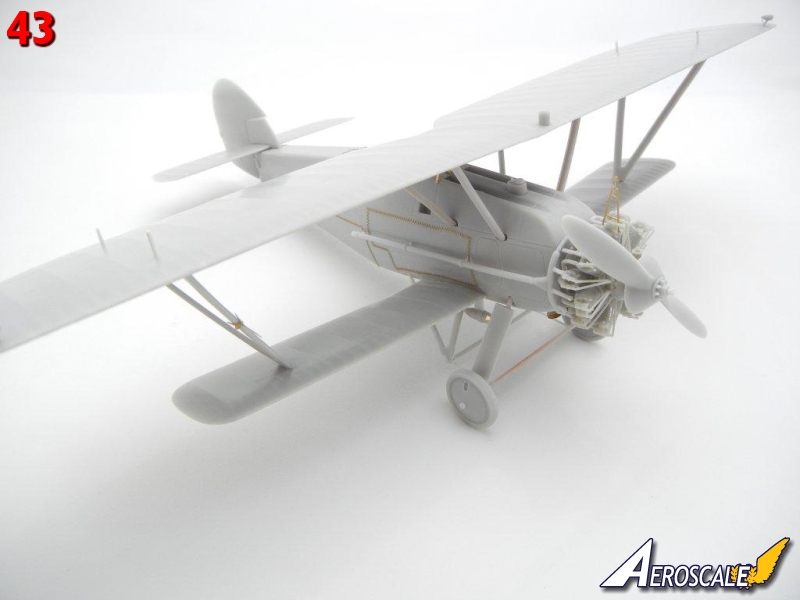
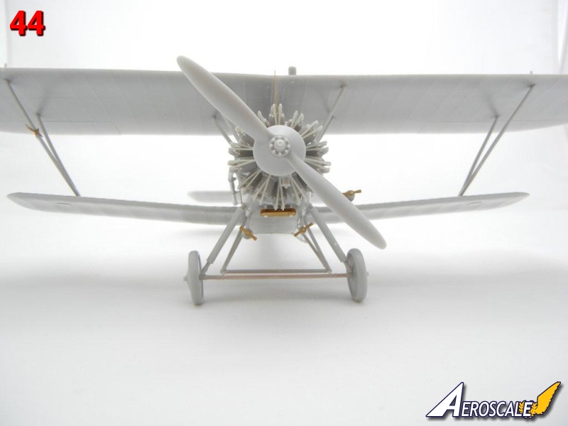
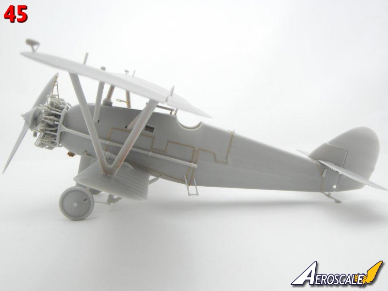
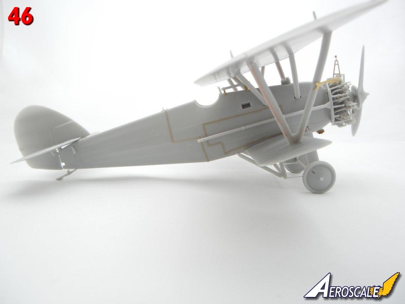
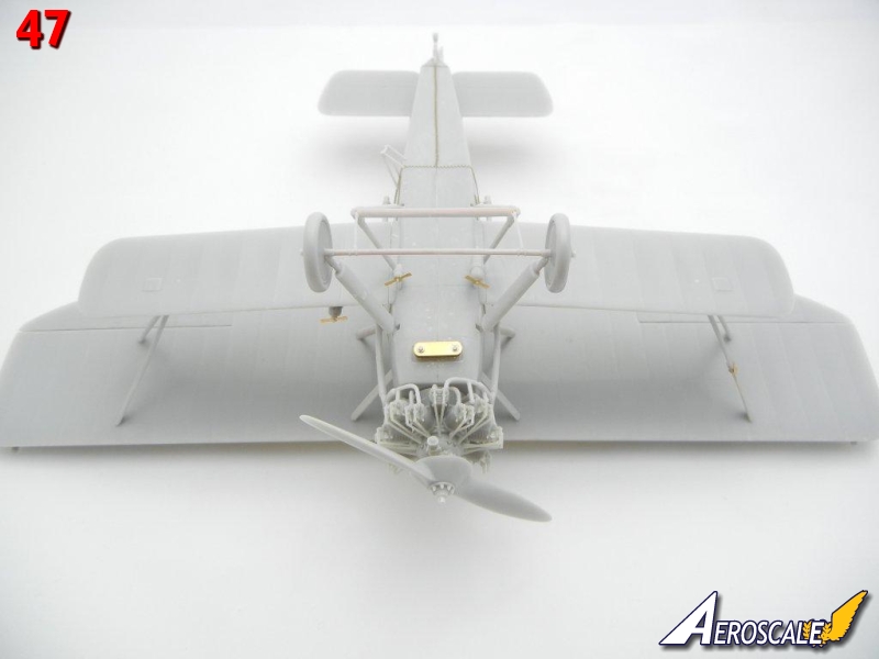
Congratulations on your newly finished Siskin! Photos 38 ~ 47 are of the completed model.
About the Author


FROM: GEORGIA, UNITED STATES
I've been modeling on and off for over 40 years. My primary interests are WW1, Interwar and WW2 aircraft, although I do build an occasional WW2 armour kit. I used to build 1/32 kits back in the 80's, but switched to 1/48 in the early 90's when all the nice new kits started showing up. I've sinc...
Comments
Copyright ©2021 by Doug Nelson. Images also by copyright holder unless otherwise noted. The views and opinions expressed herein are solely the views and opinions of the authors and/or contributors to this Web site and do not necessarily represent the views and/or opinions of AeroScale, KitMaker Network, or Silver Star Enterrpises. Images also by copyright holder unless otherwise noted. Opinions expressed are those of the author(s) and not necessarily those of AeroScale. All rights reserved. Originally published on: 2012-08-18 00:00:00. Unique Reads: 8122

WEB HOSTING BY


Copyright ©2021 AeroScale and Kitmaker Network, a subsidiary of Silver Star Enterprises
All Rights Reserved. Please read our Conditions of Use and Privacy Policy.
All Rights Reserved. Please read our Conditions of Use and Privacy Policy.