

1⁄32Building the Silver Wings Siskin
...
Post a Comment
Engine Assembly
Engine assembly is covered in the upper section of page 7 of the instructions, although you can complete this step at any time during the assembly of your model.The engine of the Siskin is quite visible as there is no cowl, but fortunately Silver Wings gives us a beautiful rendition of the Jaguar III/IV engine. While work on the engine can be repetitious, since you have to do the same thing several times, the results are a worthy engine to be the focal point of the front of your build.
I began assembly by attaching the back row of cylinders, being sure that each was facing exactly forward.
Note that when looking at the engine from the front, the left side pushrod is attached to the engine block in front of the right side pushrod. I cut one of the pushrods and test fit it to the engine block/cylinder head in the rear (right side) position and found that it was too long, so I trimmed one to fit, and then made another 6 to match. I then attached all of the rear (right side) pushrods to the engine block/cylinder heads I then test fit another pushrod to the left side (front) and trimmed it to fit, and again made 6 to match. I then fit them into position as well. Note that for either side, some pushrods did require slight trimming to ensure a good fit.
I added the front row of cylinders to the engine. Once set, I began attaching the intake pipes which fit to the left side of the cylinder heads (when viewed from the front) and to the mounting base. The longer leg of the intake pipes goes to the front row of cylinders. I had to bend mine slightly together to get the proper fit.
Once finished, I repeated the process above to attach the pushrods to the front cylinders, again going left over right at the engine block base. I added the two parts that go on the top and bottom of the front of the engine block.
You can attach the two exhaust collectors at this point. When doing so, I suggest test fitting each one and trimming the attachment points as necessary to achieve the best fit. When attaching them, I find it easiest to attach the ends first, and when set, to attach the remaining pipes pushing them into the correct position.
The two long exhaust pipes provided have small pins on them to help with attachment to the fuselage. I suggest that you temporarily place the engine on the fuselage in order to determine where these contact the fuselage, and drill out small holes. I would then cut off the pins and replace them with some metal or plastic rod, which should make attaching them after the fuselage is painted/decaled easier, as well as make the assembly stronger.
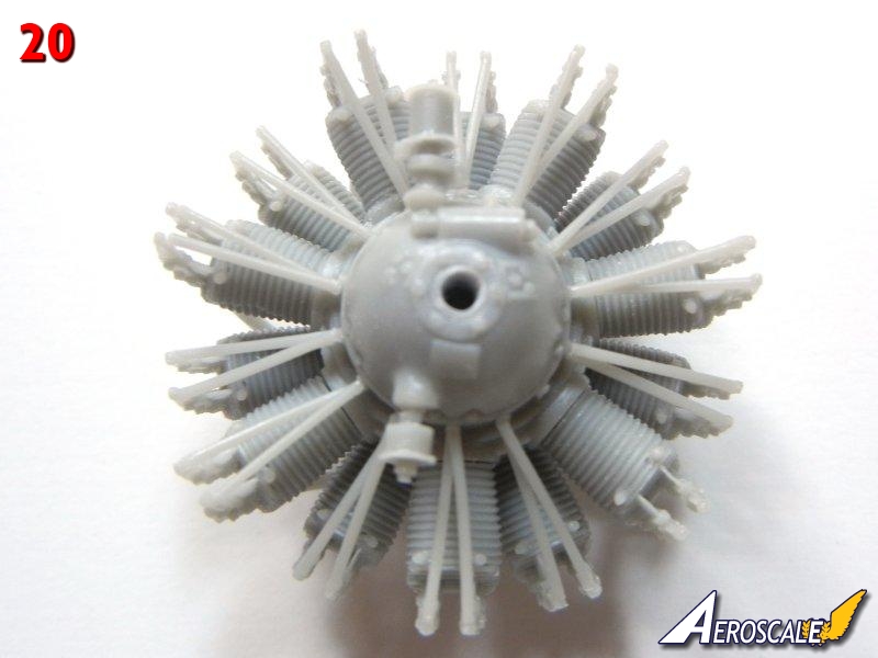
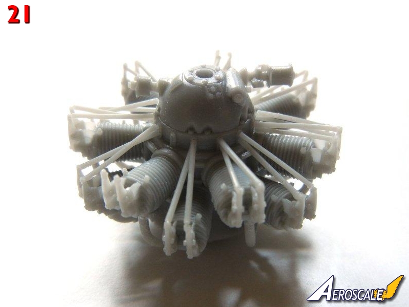
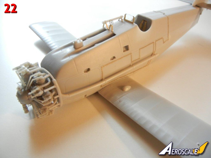
Photos 20 and 21 show the completed engine. Photo 22 shows the completed engine and exhausts in place on the fuselage.
Lower wings
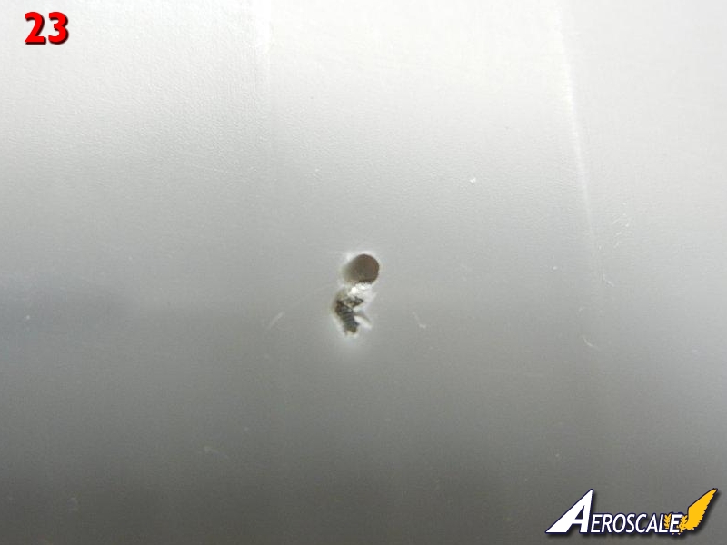
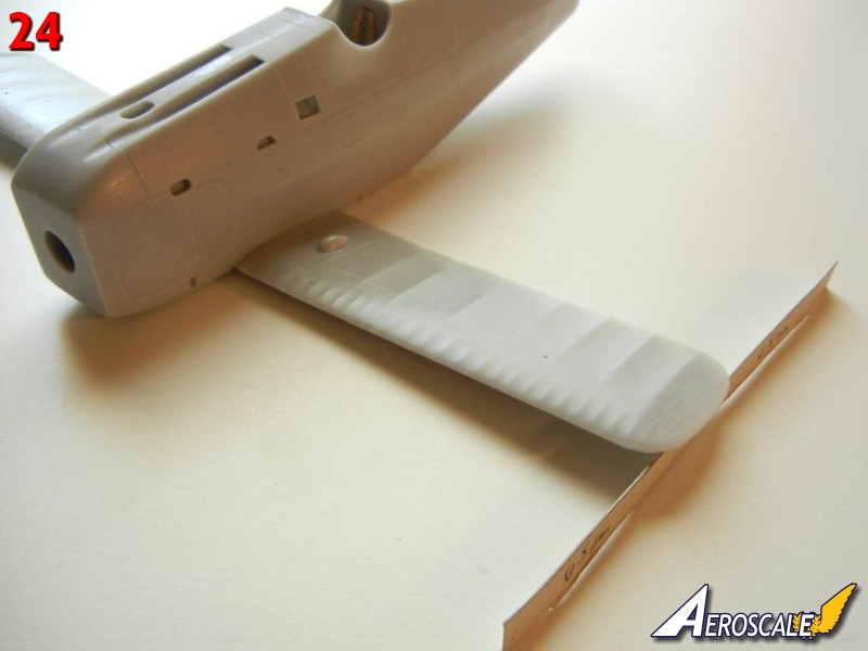
The lower wings have a metal rod inserted for strength, the remains of which can be used for attaching the lower wings to the fuselage. I recommend drilling out the appropriate hole on each side of the fuselage attachment point to accept the entire metal rod.Begin by drilling out the strut (and rigging if desired) attachment holes in the lower wings as indicated. See the article "Making Templates" in the "Tips and Reviews" section of the Silver Wings website (www.silverwings.pl) for tips on drilling out these holes at the correct angle. Note that when I drilled out the attachment point for the interplane strut, I ended up hitting the metal reinforcement rod (see photo 23). I simply drilled behind it, and thanks to the angle of the protruding strut reinforcement wire, it still fit in the correct position and cover the "mess" completely. Attach the wings to the completed fuselage assembly. Note the lower wings should have 6.5mm of dihedral at the tip according to page 6 of the instructions. I use a cardboard spacer to ensure the proper angle (see photo 24).
Empennage
The empennage is covered on page 8. As mentioned in the Parts Cleanup section, make sure that your horizontal tailplane has the 3 pins on the bottom, as these will be needed to properly mount it to the fuselage.I began by attaching the vertical stabilizer to the horizontal tailplane.
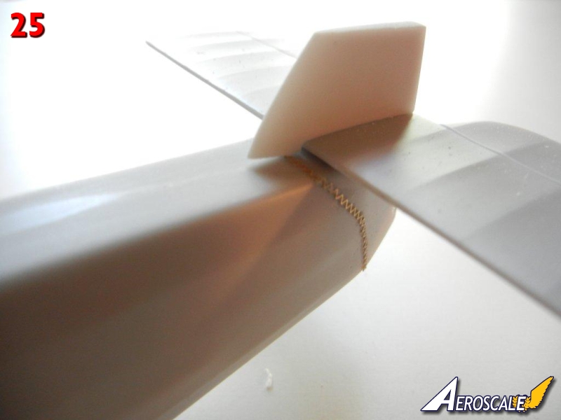
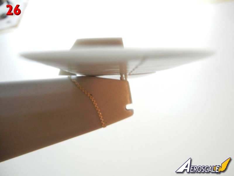
I then attached the assembly to the fuselage using the 3 pins as indicated in the instructions. Photos 25 and 26 show the completed assembly attached. Note that the vertical stabilizer should not touch the fuselage.
You can attach the rudder after it is painted and decaled if you wish.
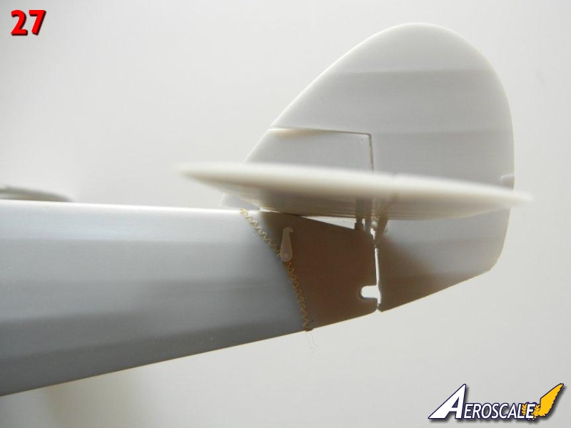
Attach the control horns to the rudder/vertical stabilizer into glue into position. You can add the small control wire crank and control wires between the fuselage and rudder control horns as shown on page 7 of the instructions during final assembly if desired. Photo 27 shows the completed empennage.
About the Author


FROM: GEORGIA, UNITED STATES
I've been modeling on and off for over 40 years. My primary interests are WW1, Interwar and WW2 aircraft, although I do build an occasional WW2 armour kit. I used to build 1/32 kits back in the 80's, but switched to 1/48 in the early 90's when all the nice new kits started showing up. I've sinc...
Comments
Copyright ©2021 by Doug Nelson. Images also by copyright holder unless otherwise noted. The views and opinions expressed herein are solely the views and opinions of the authors and/or contributors to this Web site and do not necessarily represent the views and/or opinions of AeroScale, KitMaker Network, or Silver Star Enterrpises. Images also by copyright holder unless otherwise noted. Opinions expressed are those of the author(s) and not necessarily those of AeroScale. All rights reserved. Originally published on: 2012-08-18 00:00:00. Unique Reads: 8122

WEB HOSTING BY


Copyright ©2021 AeroScale and Kitmaker Network, a subsidiary of Silver Star Enterprises
All Rights Reserved. Please read our Conditions of Use and Privacy Policy.
All Rights Reserved. Please read our Conditions of Use and Privacy Policy.