_GOTOBOTTOM
Early Aviation
Discuss World War I and the early years of aviation thru 1934.
Eduard 1/48 #8482 Fok. D.VII Weekend kit
JackFlash
_VISITCOMMUNITY
Colorado, United States
Joined: January 25, 2004
KitMaker: 11,669 posts
AeroScale: 11,011 posts
Posted: Monday, July 21, 2008 - 08:46 PM UTC
Eduard's 1/48 #8482 Fokker D.VII Weekend kit has arrived here at Aeroscale.


With an extra. The Zoom PE set for the Fokker D.VII.


The decals as described. No white borders to the crosses.
MerlinV
_VISITCOMMUNITY
Victoria, Australia
Joined: November 26, 2006
KitMaker: 608 posts
AeroScale: 602 posts
Posted: Monday, July 21, 2008 - 08:57 PM UTC
Excuse me?
A fret of etch in a weekend kit? Is that the norm from now on?

Tell you what though, Goering not withstanding, the all white scheme could make for some very interesting wheathering.

Cheers,

Hugh
JackFlash
_VISITCOMMUNITY
Colorado, United States
Joined: January 25, 2004
KitMaker: 11,669 posts
AeroScale: 11,011 posts
Posted: Monday, July 21, 2008 - 09:04 PM UTC
Hey Hugh! The etch does not come in the kit . Eduard tossed it in for the review.
Merlin
Staff MemberSenior Editor
AEROSCALE
#017
_VISITCOMMUNITY
United Kingdom
Joined: June 11, 2003
KitMaker: 17,582 posts
AeroScale: 12,795 posts
Posted: Monday, July 21, 2008 - 11:24 PM UTC
Hi Stephen

Great to see the kit and etched accessories reached you safely and so soon after leaving the hanger at Castle Aeroscale in London.

All the best

Rowan
JackFlash
_VISITCOMMUNITY
Colorado, United States
Joined: January 25, 2004
KitMaker: 11,669 posts
AeroScale: 11,011 posts
Posted: Tuesday, July 22, 2008 - 07:50 AM UTC
Greetings all;

I had a request to define the reason there are two weight stencils. The translations are from top to bottom -empty weight, and useful weight and total weight.


880kg = the over compressed 180hp
895kg = (not included here ) 200hp
906kg = 185hp (though the actual hp was often greater than generally rated. BMW IIIa was officially rated at 260 HP at 3200 m )
Repainted
_VISITCOMMUNITY
Östergötland, Sweden
Joined: April 04, 2006
KitMaker: 1,058 posts
AeroScale: 1,004 posts
Posted: Tuesday, July 22, 2008 - 08:02 AM UTC
Hi
i must say that Eduard have a very por woodsimulation on the etched dashboards, otherwise this is the typical good Eduard kit.

Larsa Q
JackFlash
_VISITCOMMUNITY
Colorado, United States
Joined: January 25, 2004
KitMaker: 11,669 posts
AeroScale: 11,011 posts
Posted: Tuesday, July 22, 2008 - 08:14 AM UTC
The following is from Göring's report on the BMW powered Fokker D.VII (Fokker D.VIIF)

"Jagdgeschwader Frhr. v. Richthofen O.U.2.8.1918
Br.Nr. 2053/II

Reports over the BMW IIIa engine.
................................................
The BMW IIIa engine continues to perform splendidly. Apart from some small deficiencies, (which are already remedied), nothing has turned out to be unfavorable. Its superiority, as compared to the other engines, (also the enemy's), is proven daily. As a rule, the "over" gas throttle position is not used under 3000 meters. Not only have we been operating in the "over" gas throttle position almost constantly throughout aerial engagement, but also at low altitude, and without any damage to the engine; (only stronger vibrating becomes apparent). Recently a pilot, who was driven down by some Spads near a balloon and had lost his orientation, flew for over a half hour with the throttle in the "over" gas position and the motor at full revs (1500-1600rpm) at a height of 100 meters pursued by the Spads. It was superior in rate to the Spads. The engine had operated smoothly and had not suffered in the slightest. Again the Geschwader, (Fighter wing), requests it for immediate and extensive delivery and asks for the immediate start of licensed production in as many factories as possible.
gez. Göring****************
Oblt. u. Geschwader-Kommandeur."
JackFlash
_VISITCOMMUNITY
Colorado, United States
Joined: January 25, 2004
KitMaker: 11,669 posts
AeroScale: 11,011 posts
Posted: Tuesday, July 22, 2008 - 09:43 AM UTC
Then here is Lothar von Richthofen's comments
"Jagdgeschwader Fhr. v. Richthofen O.U. 6.8.1918

Br.Nr. 2161/II
Kogenluft durch Kofl 7
Kofl. 7
Flz. A
Flz. B
Kdo. Zak
Baufufsicht BMW
Report on the BMW motor type IIIa.
.................................................
1.) Performance.
.........................

The BMW motor is a great advancement in the design of aircraft motors. Through increased over compression, larger bore of the cylinders, and a first-class carburetor, (which was designed particularly for higher altitudes), the Bavarian Motor factory has succeeded to manufacture a motor which makes our D airplanes, (fighter aircraft), superior to all types of enemy aircraft at higher altitudes.

Up to 2000 meters, the BMW motor operates insignificantly better than the over-compressed 160 HP Mercedes Motor (D.IIIaü 180hp) However, as soon as the "over" gas throttle position is given, the performance of the BMW motor is greatly superior to the over-compressed 160 HP Mercedes.* On average, 5000 meters in 17-20 minutes, and 6000 meters in 23-26 minutes, were achieved.

Of the known enemy aircraft, only the 300 Spads and the 160 HP Nieuport (new type) demonstrate such outstanding performance at high altitude.* Both of these aircraft types are rarely observed at the front.
..........................................................
II. Mode of operation of the BMW motor.
.................................................. .......
The motor vibration; stationary and in the air. The vibration from the over compression is not more violent than in the Alb. D.V airplane with a 160 HP Mercedes. (He is actually referencing the D.Va with the over compressed 180hp) The vibrations could be dampened by using a somewhat stronger motor mount in the Fokker D VII.

In order to not unnecessarily stress the motor, and maintain advantage, the "over" gas throttle position should be used only over 2000 meters with direct climbing or in aerial combat.* It is absolutely necessary that each pilot is informed in the mode of operation of the BMW motor, (in order to avoid unnecessary motor failure).

As soon as whole Stafflens, (squadrons), are equipped with BMW aircraft, I suggest, shipping additional reserve motors in the ratio of 2 motors for every 20 airplanes.

In the position of commander-
gez. Frhr. v. Richthofen
Leutnant and Staffelführer, (squadron leader)."
JackFlash
_VISITCOMMUNITY
Colorado, United States
Joined: January 25, 2004
KitMaker: 11,669 posts
AeroScale: 11,011 posts
Posted: Tuesday, July 22, 2008 - 10:06 AM UTC


Historian Dan San Abbott has written, ". . .D.VIIF 5125/18 was accepted on 11 September 1918. I believe it was painted at the factory, because all markings required BLV were painted on the all white finish. . ."

Oblt. Göring further wrote;
"Jagdgeschwader Frhr. v. Richthofen O.U.1.XI.1918.

Front (line) certification BMW IIIa engine.
.................................................. ....
By production and introduction of the BMW IIIa motor, the German fighter has become equal, or frequently, superior to the best enemy single-seaters. This high altitude motor is a great advancement over all past motors. Instead of diminishing in higher altitudes, its' efficiency, actually, only begins there. The working reliability is likewise satisfying.* The motor worked in each application, excellently. It must be carried out, by all means, to supply the front as rapidly as possible, and to a large extent with BMW motors, in order to keep superiority in the control of the sky. Each fighter pilot requires urgently a BMW motor.


gez. Göring
Oblt. u. Geschwader (group) - Kommandeur.
JackFlash
_VISITCOMMUNITY
Colorado, United States
Joined: January 25, 2004
KitMaker: 11,669 posts
AeroScale: 11,011 posts
Posted: Tuesday, July 22, 2008 - 10:23 AM UTC
Enough of the historical stuff on to the kit. Guess what is not in the box. Well since it is all white you won't need any lozenge right? Wrong. There should be some for the cockpit interior and there is none. Its a good thing I have spare decals.

Question: Ok if it was painted at the factory for Göring would they have used lozenge why not just use plain fabric? They painted it white.

Answer: All components at the factory were covered in lozenge (rudders too) and then the areas requiring it were overpainted white. This included rudders and vertical stabilizer .Exsisting fabric examples prove this.
CaptainA
_VISITCOMMUNITY
Indiana, United States
Joined: May 14, 2007
KitMaker: 3,117 posts
AeroScale: 2,270 posts
Posted: Tuesday, July 22, 2008 - 11:21 AM UTC
I love those BMW Inline 6's.
JackFlash
_VISITCOMMUNITY
Colorado, United States
Joined: January 25, 2004
KitMaker: 11,669 posts
AeroScale: 11,011 posts
Posted: Tuesday, July 22, 2008 - 12:10 PM UTC
Then here is a bit of fun for you Carl.


These are reference images to the real engine and Eduard's version of the BMW IIIa. The Fokker D.VIIF was the specific identifier for the late production BMW powered version. Then why did Eduard say in their instructions to used the parts for the Mercedes D.IIIaü? Can I get a witness here? OOOOOOPPPPPS!


Well at least we know why they provided the other weight table in their decals.
CMOT70
_VISITCOMMUNITY
Victoria, Australia
Joined: August 23, 2007
KitMaker: 629 posts
AeroScale: 539 posts
Posted: Tuesday, July 22, 2008 - 03:55 PM UTC
Regarding engines, you can always use a spare Roden BMW one anyway. It fits into the Eduard kit okay with only minimal adjustments. And it's a better representation pf the BMW anyway in my opinion. And since every Roden kit comes with 2 engines, most people have spares.

Andrew
JackFlash
_VISITCOMMUNITY
Colorado, United States
Joined: January 25, 2004
KitMaker: 11,669 posts
AeroScale: 11,011 posts
Posted: Tuesday, July 22, 2008 - 08:45 PM UTC
Greetings Andrew, you are correct though I would rather save the Roden item for a time when I have an exposed or partially exposed engine compartment. The Roden BMW is a jewel, no doubt.

Here is the instruction for Eduard's first issue. So they should have got it right with the Weekend kit.
JackFlash
_VISITCOMMUNITY
Colorado, United States
Joined: January 25, 2004
KitMaker: 11,669 posts
AeroScale: 11,011 posts
Posted: Tuesday, July 22, 2008 - 10:40 PM UTC
Well here we go.


The inline motor assembly is a generic representation that has pieces for the Mercedes D.IIIaü 180hp (PP B 5, 6, 8, 14 - C 4, 13, 34 ) or the BMW IIIa 185 hp assembly (PP B 5, 6, 8, 13 - C 4, 13, 34 .) Truthfully, most non WWI modelers won’t know the difference. Check the references provided for some keynote differences in the types installed. The cylinder jackets of both engines were the color of “blued metal.” The BMW sat higher in the compartment so about 1" more of the cylinders could be seen. Its air induction pipes ( PP B 13) were unified where the Mercedes (PP B 14 )was divided. The immediate visual difference in the early Mercedes D.III 160hp / D.IIIa 170hp and its progeny the D.IIIaü 180hp or D.IIIav 200hp are in the rocker boxes above the cylinder jacket heads. On the early D.III and D.IIIa motors the rocker springs (B 6) are centered on the sides of the rocker box covers. On the D.IIIaü and D.IIIav motor the springs are located on the forward leading edge of the same covers. They were also that way on the BMW IIIa 185hp. The rest is below the cowling and not readily visible.

Several good manufacturers ( specifically ‘Roden’as has been mentioned) note the difference and have two distinct castings. The Mercedes D.III160hp was outclassed by 1917. The Mercedes D.IIIaü 180hp was the standard engine in both of the Albatros late built D.V and all D.Va types starting in late 1917 and then the Fokker D.VII through 1918. Then in early 1918 came the Mercedes D.IIIav 200hp. The BMW IIIa 185hp was highly prized by pilots. Many, many D. III and IIIa type motors were rebuilt to the D.IIIaü specs at the airparks as the war progressed. That is why some captured examples had motors with the i.d. designation of D.III 160hp cast into their crankcases. This has caused the misconception that the standard 160hp and 170 hp were used in 1918 at a time when they had become obsolete. Often these were referred to as “160hp over-compressed engines.”
JackFlash
_VISITCOMMUNITY
Colorado, United States
Joined: January 25, 2004
KitMaker: 11,669 posts
AeroScale: 11,011 posts
Posted: Wednesday, July 23, 2008 - 08:09 AM UTC
Remembering the old Royal build thread I have ressurected a few of Mal's images of his Fokker D.VIIF build to salt in here while mine is curing on the bench.

Royal kit built
Royal kit Feature

And here is a bit of fun concerning the early issue of Eduard's Schwerin built Fokker D.VII (Mercedes powered) by some plugger hereabouts.
Eduard's 8132 Combo
JackFlash
_VISITCOMMUNITY
Colorado, United States
Joined: January 25, 2004
KitMaker: 11,669 posts
AeroScale: 11,011 posts
Posted: Wednesday, July 23, 2008 - 08:10 AM UTC
Next the cockpit flooring (PP A 7 ) The rudder bar ( PP C 33 ) inserted through the flooring (PP A 7) and needs a vertical bar attached centrally. Like the DML Fokker Dr.I set up, this vertical column should angle back and up behind the ammunition box (PP A 16.) On the control column (PP C 27) note the throttle lever has one handle We also have photos where two are present. Check your references. Set the rudder bar (PP C 33 ) to the desired position to compliment the attitude you have chosen for the rudder. Scratchbuild an aileron control “V” for cables and attach the “V” at the front end of the lower control bar molded to the cockpit flooring (PP A 7) . Also add the compass ( PP C 14 & PE 10.) Also here, add bent and shaped brass wire for the throttle and the cables for the Spandau machine guns. Later you will have to add all the control rigging material to the elevator control column(PP C 27 ) and the rudder bar column (PP C 33 ) when the cockpit rear bulkhead / screen (PP A 11) is added. Some of these cables should to go through holes that you need to cut in the rear bulkhead / screen (PP A 11 .) Check your references for the various cables and wiring that are attached to these units.


The seat (PP B 12 & 15 ) sets into its supports that are to be built up in a box frame ( C 17, 18 & 32) and attached to the rear cockpit bulkhead / screen (PP A 11.) I trimmed down the inside surfaces of the seat ( PP B 12.) ( The seat was known to be covered in fabric that was held by attaching it to eyelets in the seat back’s outer rim.) I also deleted the seat cushion (B 15.) As parachutes had come into use the seat was made deeper to accommodate the chute pack as a cushion. There was not any tucked leather or buttons on the chute pack surface. In the cockpit rear bulkhead / screen (PP A 11) note there needs to be holes for the rudder control cables to pass through. Next remember the rudder control cables that will be added between the bar and the stirrups will need to go through these holes. Whatever the fuselage covering use the same covering on the bulkhead/screen (PP A 11.) In this case of 4 or 5 colour lozenge. The pilot’s shoulder harness straps (PE 1) are attached to the seat framing (PP C 18)behind the seat (PP B 12.) Next the location for the fuel pressure hand pump ( PP C 10.) You my want to add a half loop of painted brass wire to simulate the air hose leading toward the front of the cockpit strapped to the framework.


JackFlash
_VISITCOMMUNITY
Colorado, United States
Joined: January 25, 2004
KitMaker: 11,669 posts
AeroScale: 11,011 posts
Posted: Wednesday, July 23, 2008 - 09:02 PM UTC
First of all choose which fuselage versions you are going to build. You can replace the molded cockpit structure in the fuselage halves (PP F 1-3 , 13 ) with painted brass rod sections or after you apply the interior surface lozenge decals and they thoroughly set, dry brush the details with a light grey or grey-green to bring out the airframe skeleton. Note that the factory printed lozenge pattern fabric used on the Fokker D.VII showed through the interior of the cockpit sides in reverse in lighter shades.


There is no main fuel, reserve fuel & oil tank assembly. Then we see the method of attachment of the engine and the typical Eduard bearing shelf to the raised edges within the engine compartment. Note Eduard has provided for a vertical installation of the Firewall (PP A 8.) This is incorrect. This should have an incline at the top toward the engine compartment with a cutout for the engine decompression bell. To do it right you will have to erase the forward most, lower locating ridges. Then line the rear face of the firewall up on the outside of the forward most, upper locating ridges. On the early Schwerin fuselage (PP F 2 & 13) without louvres its not too noticeable. Out of the box the pilot's right side upper engine cowling has a larger cutout for the cylinders and exhaust opens up that area for scrutiny. On the Late style Schwerin version (PP F 1 & 3)out of the box the cowling opening for the engine cylinders is larger and easier to see the firewall is too far back. Note in the image above I opened up the pilot's left side cowling to allow for the raised air intake pipes.
JackFlash
_VISITCOMMUNITY
Colorado, United States
Joined: January 25, 2004
KitMaker: 11,669 posts
AeroScale: 11,011 posts
Posted: Wednesday, July 23, 2008 - 09:10 PM UTC
Concerning the instrument panel (PP A 14 or PE 14 & 15 ), I will “usually” paint Fokker company instrument panels black and give OAW or Albatros types a varnished wood look. Eduard has pre-painted theirs a cream with an orange brown grain colour. They have also given the modeler a great set of photoetch instrument panel parts and fuel gauges for two complete kits. I also added a hand crank spare part as a handle to magneto and flip levers (PE 25 X 4) to fuel and air controls. I also add the tachometer (PE 11) dial to the machine gun rear brace (PP C 28.) Finally they discuss the engine compartment assemblies. As mentioned earlier cowling side panels are a known hallmark in determining the parentage of your D.VII. But in mid-summer the upper cowlings would be removed during flight operations. This would be typical of a machine in mid to late (June - Nov.)1918. The late Fokker types came to the front on very late summer early fall (autumn) 1918. Now assemble the fuselage halves (PP F 1- 3, 13) with its internal component assemblies. If I were to display any Eduard 1/48 Fokker D.VII kit with the engine cowlings removed I would use the Roden versions.


JackFlash
_VISITCOMMUNITY
Colorado, United States
Joined: January 25, 2004
KitMaker: 11,669 posts
AeroScale: 11,011 posts
Posted: Wednesday, July 23, 2008 - 09:16 PM UTC
Here we assemble the lower wing parts (PP A 2 & 3, B 1.) One could actually insert spars held in place with double sided tape or glued in place. This type of wing assembly is great for the modeler who wants to simulate damage. By thinning down the inner surfaces, internal structure is easy to replicate. Also, before putting the lower wing together sand the vertical edge of the lower wing halves at the roots of all lower wing components (PP A 2 & 3, B 1.) The unmodified fit between the lower wing an fuselage is tight and cause anhedral just like the Roden kit. This fix will eliminate the fit problem. Do Not narrow the whole fuselage by taking away from the center union area.


Here three edges are modified and one edge is shown unmodified to let you know how much you need to remove.
JackFlash
_VISITCOMMUNITY
Colorado, United States
Joined: January 25, 2004
KitMaker: 11,669 posts
AeroScale: 11,011 posts
Posted: Wednesday, July 23, 2008 - 09:23 PM UTC
Here is the axle wing (PP B 7, F 5 & 6 ) with the mid section (PP B 7) I routed out the plastic axle will be replaced it with a brass rod of appropriate diameter.

CaptainA
_VISITCOMMUNITY
Indiana, United States
Joined: May 14, 2007
KitMaker: 3,117 posts
AeroScale: 2,270 posts
Posted: Friday, July 25, 2008 - 12:37 PM UTC
Thanks Stephen, I think history class was the only one where I did not fall asleep. I really love your history packed, information packed, builds.

So which of the kits do you think is better, the Roden D.VII or Eduard D.VII?
JackFlash
_VISITCOMMUNITY
Colorado, United States
Joined: January 25, 2004
KitMaker: 11,669 posts
AeroScale: 11,011 posts
Posted: Friday, July 25, 2008 - 05:24 PM UTC

Quoted Text

Thanks Stephen, I think history class was the only one where I did not fall asleep. I really love your history packed, information packed, builds. So which of the kits do you think is better, the Roden D.VII or Eduard D.VII?


Thank you Carl. They are both very decent kits. But both have their specific high points.

Roden ; parts for one of two complete detailed specific engines. Internal structure are separate molds. Option for either closed cowling or totally open cowling. Cockpit details are good with the exception of the kit flooring. It does have the fuel pressure hand pump for the fuel tank. Landing gear legs are too weak and should be replaced. Part of Poland does a detail fret for this kit.

Eduard ; parts for one of two engines, details minimal. Internal structure is molded in and minimal. Cowlings come molded closed on all issues. Two fuselages per kit. You can choose either early or late. Cockpit has most details except for the fuel pressure hand pump for the fuel tank. Landing gear legs are good and don't need to be replaced. Part of Poland does NOT have a detail fret for this kit.

It depends on how you want the kit displayed. Open engine compartment or closed. What you want to scracth build or what aftermarket fret you want to use. For just the shear weight of details and aftermarket items available. I go with the Roden kit. for a quick and easy build Eduard. Just my opinion folks.
JackFlash
_VISITCOMMUNITY
Colorado, United States
Joined: January 25, 2004
KitMaker: 11,669 posts
AeroScale: 11,011 posts
Posted: Saturday, July 26, 2008 - 01:07 PM UTC
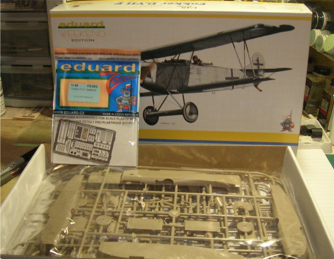
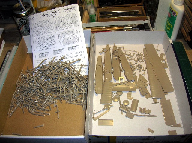
Just a bit of an update folks. The overall white scheme of this bird is making the build move along smoothly. Everything but the outside of the fuselage is painted. The fuselage is almost ready to close up. A few rigging lines and etc. I have modified this build to match some late type installation practices.

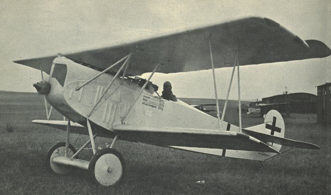
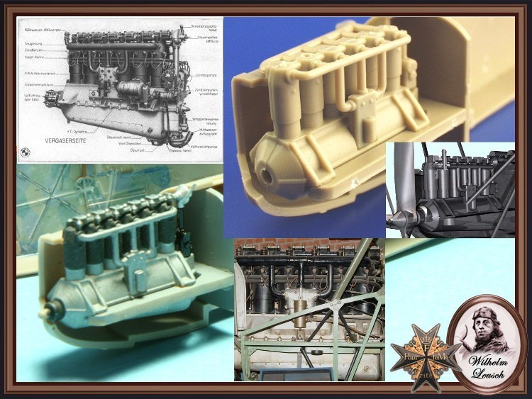
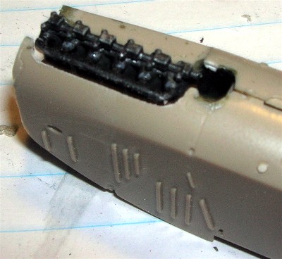
Here is the cockpit of the Deutches Museum original Schwerin Fokker D.VII 4404/18. The gun position has been fared over but the front gun mounts are still inplace. Note the position of the compass as attached to the control column. The interior is overpainted a medium green (probably post war as a method to keep deterioration of the fabric down to a minimum. The instrument panel was painted black and may be a metal replacement item too. But note the instruments and their locations.


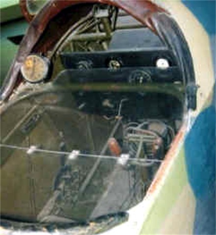
The center image has a clear, hinged "sneeze guard" over the cockpit.


I have always believed that the Fokker Schwerin D.VII instrument panels were over-painted black. 
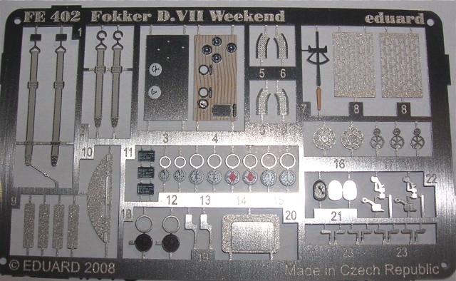
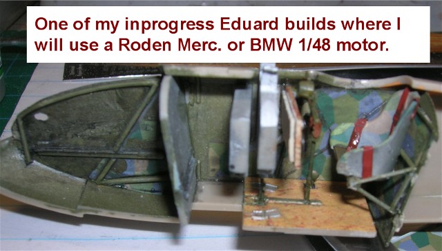
OAW & Albatros seem to have all been varnished wood. I have compromised a bit here, ane have gone with a dark wood simulated instrument panel. Mostly because some of the details tend to get lost on a black instrument panel. The already black "Bosch" starting magneto, flip levers, their base plates and name plates in this scale disappear unless you dry brush the whole affair in a lighter slate grey.

Also the control column is a brass rod with the kit auxilary throttle and hand grip added.

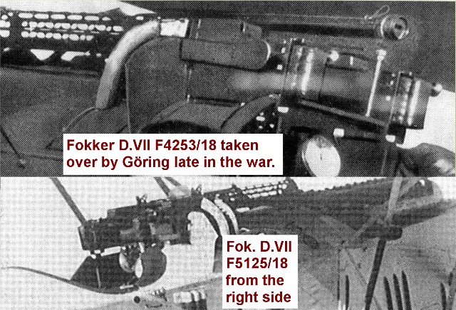
On the instrument panel it seems at least on some late production Schwerin built Fokker D.VII that the tachometer was dropped from the rear machine gun brace to being mounted in the instrument panel. After looking at various images available to me I can say that this was not a general rule. 
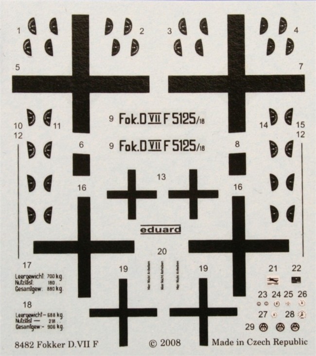
Certainly the tach on D.5125/18 was on the rear gun brace (as photos bear out.)

While I am going with an all white scheme there will be a bit of a surprise in the mix. I will spend some time carefully trying to texture and weather this kit. For personal reasons I will be changing the identity of this machine to show what you can do with kit serial numbers with a historical touch.
JackFlash
_VISITCOMMUNITY
Colorado, United States
Joined: January 25, 2004
KitMaker: 11,669 posts
AeroScale: 11,011 posts
Posted: Saturday, July 26, 2008 - 05:49 PM UTC
The half moon - cabane strut attachment points(PE 26 X 8 ) that Eduard include as photoetch in their other kits are for the underside of the top wing assembly are a nice touch to add as well. Since I have extras from my previous Royal build I will use them here. As can be seen in my previous posting of this kit's PE fret these are not present.

Since the Spandaus will come quickly here I will review my information on the set up for the Fokker D.VII F. The BMW sat higher (almost an inch in height difference from the Mercedes D.IIIaü.)

The images I will post next of Göring's white D.5125/18 and early D. 4253/18(also an F was originally flown by Udet. But Göring took it over later on and painted the rear fuselage at tail unit white.) The guns were set more than 2.5 inches higher. Both of these aircraft were modified to Göring's specifications and had deflector plates on the sides of the gun breeches angling out. There was a tray from these that laid under the breeches and caught the spent shells and deflected them into the slip stream away from the cockpit. This is a rare set up and is noteworthy to the builder dedicated to building D.5125/18.


Here is the same layout of raised guns on another Eduard Fok. D.VIIF fuselage. (Because the BMW sat higher.)


One place to find excellent references and better images of these on this an other WWI related subjects is,

http://www.windsockdatafilespecials.co.uk/
See; "Von Richthofen’s Flying Circus". Written by Greg VanWyngarden, this superb 68 page book provides extensive pictorial coverage of Jagdgeschwader Nr.I’s Jastas 4, 6, 10 and 11 – the famous circus! With 183 archive photos, 12 mono profiles and 10 colour pages packed full with over 47 exacting colour profiles by Ray Rimell. Very Limited stocks! £16.95.

 _GOTOTOP