Early Aviation
Discuss World War I and the early years of aviation thru 1934.
Fly 1:48 Macchi M5
Louis
_VISITCOMMUNITY
Bas-Rhin, France
Joined: May 21, 2006
KitMaker: 472 posts
AeroScale: 471 posts
Posted: Tuesday, July 13, 2010 - 06:59 AM UTC
Thank you Terri.

Some pictures have disappeared...


Louis
_VISITCOMMUNITY
Bas-Rhin, France
Joined: May 21, 2006
KitMaker: 472 posts
AeroScale: 471 posts
Posted: Tuesday, July 13, 2010 - 10:06 PM UTC
The boundaries between the bottom and sides of the hull seen from the front should be more arched but I can not:


Regards
thegirl
_VISITCOMMUNITY
Alberta, Canada
Joined: January 19, 2008
KitMaker: 6,743 posts
AeroScale: 6,151 posts
Posted: Wednesday, July 14, 2010 - 06:18 AM UTC
Hi Louis !

Personally , I like the shape of the hull so far . This method is not easy to do and you are pulling it off masterfully !

I don't understand the reason of the foam blocks

How does this aid in support for the putty , wouldn't something more solid be better suited for this ?
Louis
_VISITCOMMUNITY
Bas-Rhin, France
Joined: May 21, 2006
KitMaker: 472 posts
AeroScale: 471 posts
Posted: Wednesday, July 14, 2010 - 07:53 AM UTC
Hello Terri,

with the foam block I am not obliged to put too much putty into holes. It's a long time to dry and I feel that my putty distort the plastic when I put too much...


First I put "milliput", it does not melt the polystyrene, after I put Tamiya.

Regards.


Le même montage en français
Louis
_VISITCOMMUNITY
Bas-Rhin, France
Joined: May 21, 2006
KitMaker: 472 posts
AeroScale: 471 posts
Posted: Wednesday, August 18, 2010 - 10:54 AM UTC
Salut,


Hello,


The hull is almost over.

on forward the cockpit, The deck is made of plastic card glued to the internal structure. The sides of the deck are nearly vertical while the upper deck is almost flat. I have done in three parts: the top (green) is pasted first. The edges of the deck (red) are then glued on a square spindle (blue). Then we cut the excess, we sand and we chew...


Cutting the hole in the cockpit is made ... I tried helped templates circular paper (diameter 23mm) to trace its contours.


The deck should be fine because you have to drill the windows. I removed the internal structure because they are seen through the windows and the hole in the cockpit. So all that is cut with reamer and sandpaper.

Before:


AFTER:


At the rear of the cockpit I put slipways in order to give a very rounded shape of the deck. It becomes almost vertical at the sides. The slipways to the top of the deck shall not be implemented because on my first test structure was too high.

The fairing on the back of the headrest is then glued and chewed.


The base of the stabilizer comes from the original kit:


I used Tamiya putty but it deform plasticard and creates some "cavity ". It is therefore better to use another one.

The fairing of the headrest is too high it seems.


Best regards

Le même en français
thegirl
_VISITCOMMUNITY
Alberta, Canada
Joined: January 19, 2008
KitMaker: 6,743 posts
AeroScale: 6,151 posts
Posted: Thursday, August 19, 2010 - 03:43 AM UTC
The fuselage looks great Louis ! Excellent job on her so far . This has been very interesting to watch so far and I look forward to the next up-date .
Louis
_VISITCOMMUNITY
Bas-Rhin, France
Joined: May 21, 2006
KitMaker: 472 posts
AeroScale: 471 posts
Posted: Monday, August 23, 2010 - 10:40 AM UTC
Thank you Terri.

The pictures showing the surfaces of the wings are few. One or two pictures show the top surface of the upper wing. A little more for the rest of the surfaces.
Between each rib there is a dip too deep. I tried to sand ribs and fill the gaps with a bit of painting. It's better (even though it's difficult to see on the pictures ...) but it is too deep:

before:


after:


The lower wing is enhanced with putty. It's pretty simple and quick to do. Be careful not to twist the wing in the sanding or risk seeing the chews come off in large sheets like icecube falling off their tray when you twist it....

I hesitate to do that on the upper wing is very long and very flexible.
The underside is sanded smooth.


The lengths that are at the end of the "windsock" does not match the plan. The kit wings were almost the size announced by the plan and I do not find the errors posted on other sites.

It lacks about 1mm on each side of the upper wing and about 1 ° to the arrow. The underside of the wing should be nearly smooth and the top also with "ribs" visible.
The images show the dimensions of the plan and lengths on the wings "Fly".


The lower wing is also correct, it will "just" take a little shape of each end (cf. hatched) and its surface.


I hope I read the plan correctly ...

Regards.

Louis
_VISITCOMMUNITY
Bas-Rhin, France
Joined: May 21, 2006
KitMaker: 472 posts
AeroScale: 471 posts
Posted: Monday, August 23, 2010 - 07:39 PM UTC
All measurements are written on the original plan (like 5983...).
JackFlash
_VISITCOMMUNITY
Colorado, United States
Joined: January 25, 2004
KitMaker: 11,669 posts
AeroScale: 11,011 posts
Posted: Tuesday, August 24, 2010 - 03:01 AM UTC
Most impressive!
thegirl
_VISITCOMMUNITY
Alberta, Canada
Joined: January 19, 2008
KitMaker: 6,743 posts
AeroScale: 6,151 posts
Posted: Tuesday, August 24, 2010 - 03:06 AM UTC
Most impressive indeed Louis . I have heard their was small issues with Fly's wings . Nice way on handling this
gajouette
_VISITCOMMUNITY
Texas, United States
Joined: February 01, 2007
KitMaker: 365 posts
AeroScale: 356 posts
Posted: Tuesday, August 24, 2010 - 04:04 AM UTC
Louis,
I'd have to agree with Terri and Stephen,Most Impressive ! Your work on the scratch built fuselage is simply amazing,and so well done too.Excellent progress on your wings.Congratulations on one Outstanding thread my friend.
Highest Regards,
Gregory Jouette
Louis
_VISITCOMMUNITY
Bas-Rhin, France
Joined: May 21, 2006
KitMaker: 472 posts
AeroScale: 471 posts
Posted: Friday, September 03, 2010 - 09:06 PM UTC
Thank you very much!

The wing is more difficult than I expected, so I started the engine....

Photographs of engines:

VIRTUAL MUSEUM - The Memory - The Collections

Isotta Fraschini V 4 B:

Isotta Fraschini V4 B

An other one V4B:


MOTORI


One plan and two very good pictures of the left face in the Windsock Datafile n°078 - Caproni Ca3 p34 et p35

Photos of a V4B (I believe) on a Caproni ca36:

Caproni Ca 36


A V6 I believe:

Miscellaneous engines


I started the engine and a group of two cylinders, it is not quite symmetrical, I would hide it under the hood


I must make two identical one, and everything else....

Regards.

Rittmeister 194En français Macchi M5 1/48 FLY

A+
Louis
_VISITCOMMUNITY
Bas-Rhin, France
Joined: May 21, 2006
KitMaker: 472 posts
AeroScale: 471 posts
Posted: Sunday, September 05, 2010 - 12:12 AM UTC
The "protective cover " of the cylinder is a piece of plastic (0.4mm) wrapped around two nails (2mm diameter) held in a vise. The height of the "protective cover " is 3.7mm, the width at its summit 7mm, 5.6mm at its base. Measurements are not guaranteed. They can properly position the nails. To remove the "protective cover " you must pull out nails from the vise and it is difficult to find the same positions again. So plan a system to maintain the angle between the nails when the clamp is loose (a large piece of putty on their heads, perhaps?). Try to hide the seam as best you can. The photo shows what not to do ....


The cylinders are rotated into a piece of plastic (diameter of the visible part 2.8mm, height 2.5mm), I have done better to use pieces of tubes but I have thought that once the finished work.


The cylinders are glued by two and slipped the "protective cover " over.


The total height is 9.9mm.
The reinforcements which surrounds the "protective cover " are aluminum tape.


The nuts at the base of the sparks are PART PE

Regards.


La même chose en Français
Louis
_VISITCOMMUNITY
Bas-Rhin, France
Joined: May 21, 2006
KitMaker: 472 posts
AeroScale: 471 posts
Posted: Sunday, September 05, 2010 - 10:44 AM UTC
The nails form a V. Its tip is down. If you place the V pointing up, you can remove the "protective cover " without removing nails...Thank you Philippe.
Louis
_VISITCOMMUNITY
Bas-Rhin, France
Joined: May 21, 2006
KitMaker: 472 posts
AeroScale: 471 posts
Posted: Thursday, September 09, 2010 - 07:07 AM UTC
A lot of pictures on this link sent by Joachim .

Thank you very much to him.


http://www.wwi-models.org/app/sbj/srch/Macn.php?action=uArchList&subjId=185
Louis
_VISITCOMMUNITY
Bas-Rhin, France
Joined: May 21, 2006
KitMaker: 472 posts
AeroScale: 471 posts
Posted: Thursday, September 23, 2010 - 09:09 AM UTC
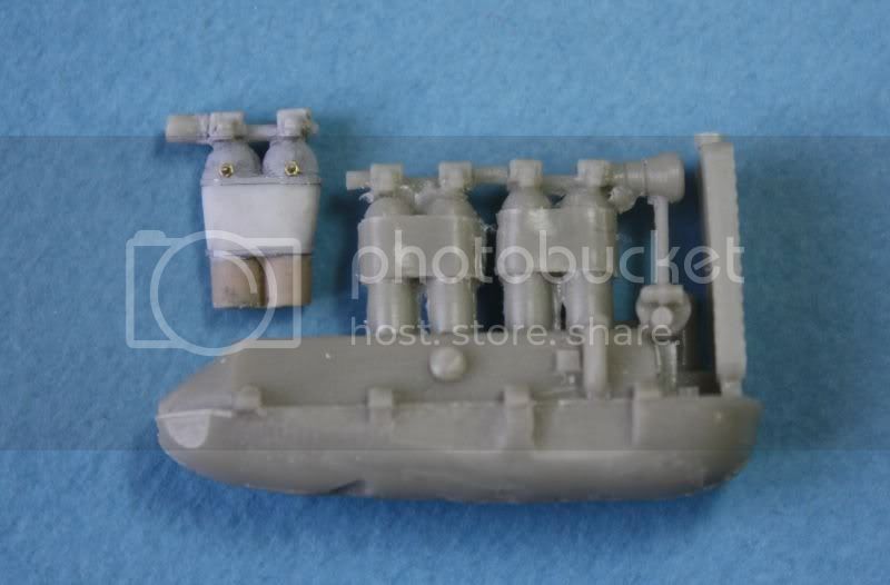
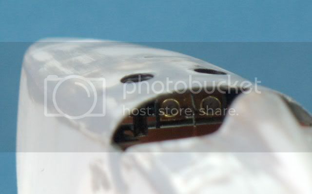
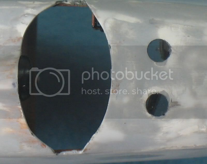
I found no picture or information about the installation of Vickers machine guns. I chose to install two guns Fiat.


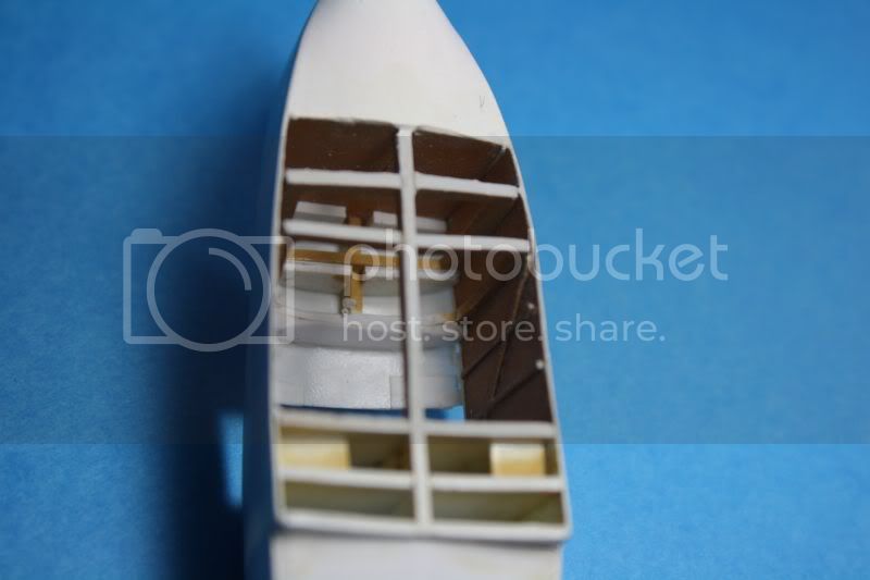
I used the design of the cockpit appeared in the Windsock datafile and the following documents:

A pdf document on the gun "Fiat Revelli model 1914" in English:

http://www.smallarmsreview.com/pdf/Fiat.pdf

Another Italian with technical drawings of the weapon:

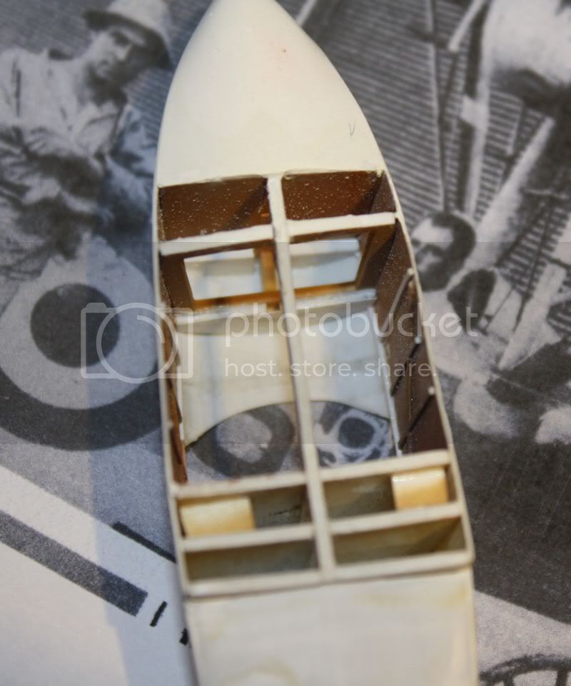
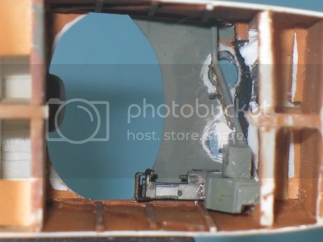
http://www.armigeridelpiave.it/SELEZIONI/La%20mitragliatrice%20FIAT%20da%20aviazione.pdf

The weapons are installed with the left side up to be able to recharge. I am well used to detail the right side ... before I realized my mistake.


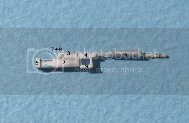
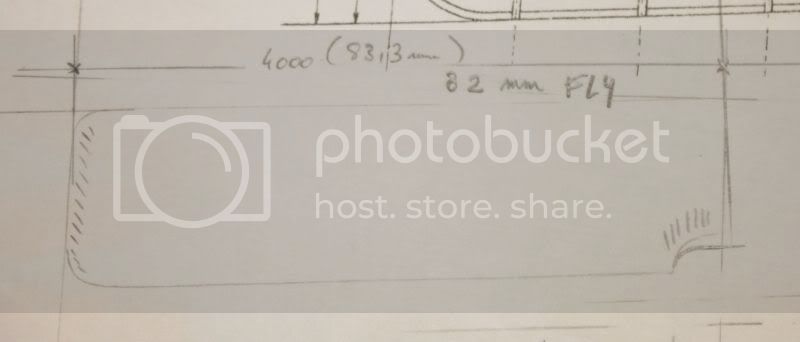
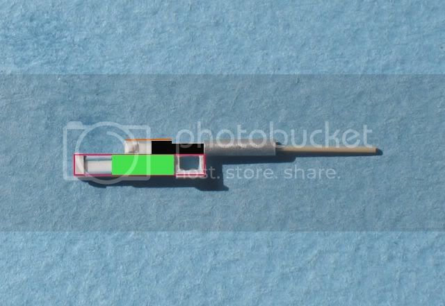
All lengths are in mm

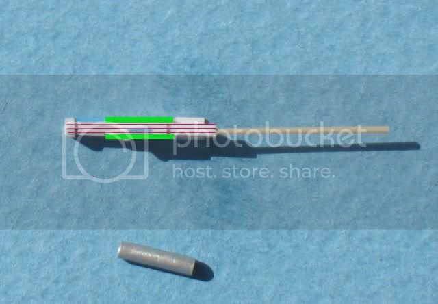
Stage 1: 3 parts : (1,5 X 0,25) X 93 shorten it to 2mm. Drill the hole
for cartridge clip. (red parts)

Stage 2: 2parts: (1,5 X 0,25) X 4,56 (green parts)

Stage 3: 1part: (1 X 1) X 3,35

Stage 4: 1part: (0,75 X 0,75) X 2,4 or (1x0.75) add 1mm to fix the sheath of the
barrel of the weapon

Stage 5: 3parts: 0,7 X 1,65 (?) X 0,25

Stage 6: Length 5mm. Diameter: 1,5mm « flan dish aluminium »

Stage7+8: 0,75X0,75 0,5X0,5 a thin slice....

Stage9: 1part: 0,25 X 2,3 X 1,8

Stage10: 13,5 and remove the added length to the fourth stage (1mm).
diameter: 0,4 ?

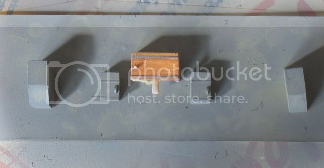
Stage11: Build black part, 0,1mm x 1 x 2

Stage12: Build orange part 0,1x 1,3 (?) x 3,35 the orange cover is a bit wider
than the part 3

Blue: Plastic (square section) stretched


1,5x0,25 1x1 0,75x0,75 0,5x0,5 come from evergreen's references.


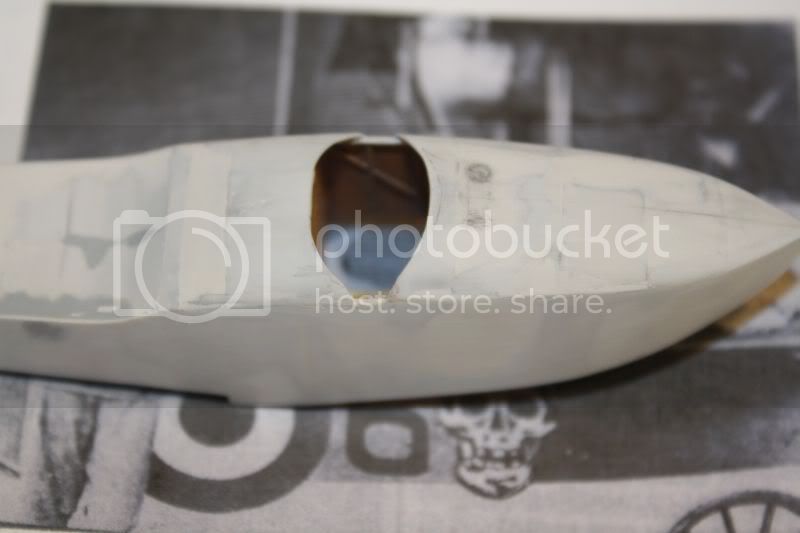
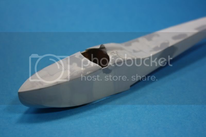
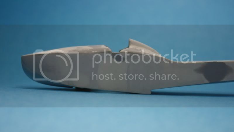
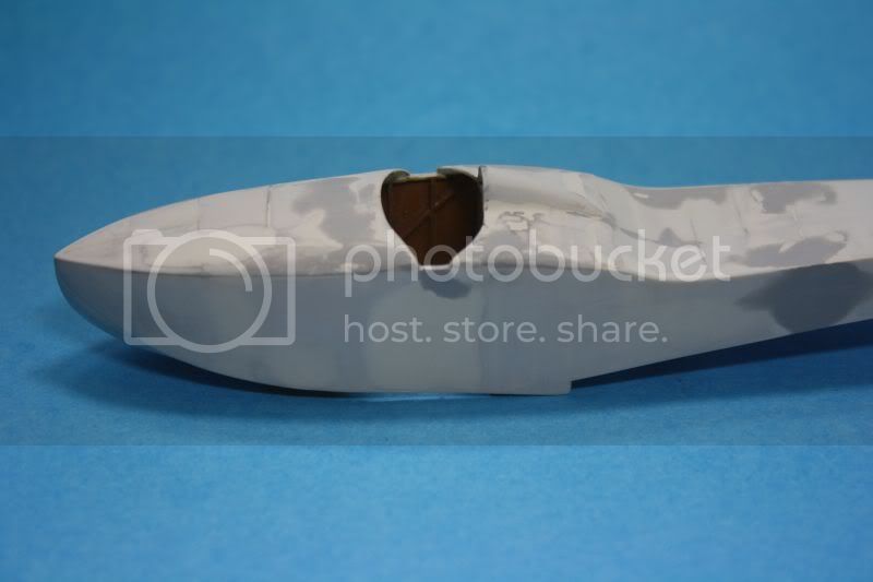
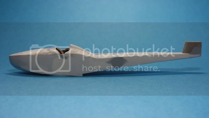
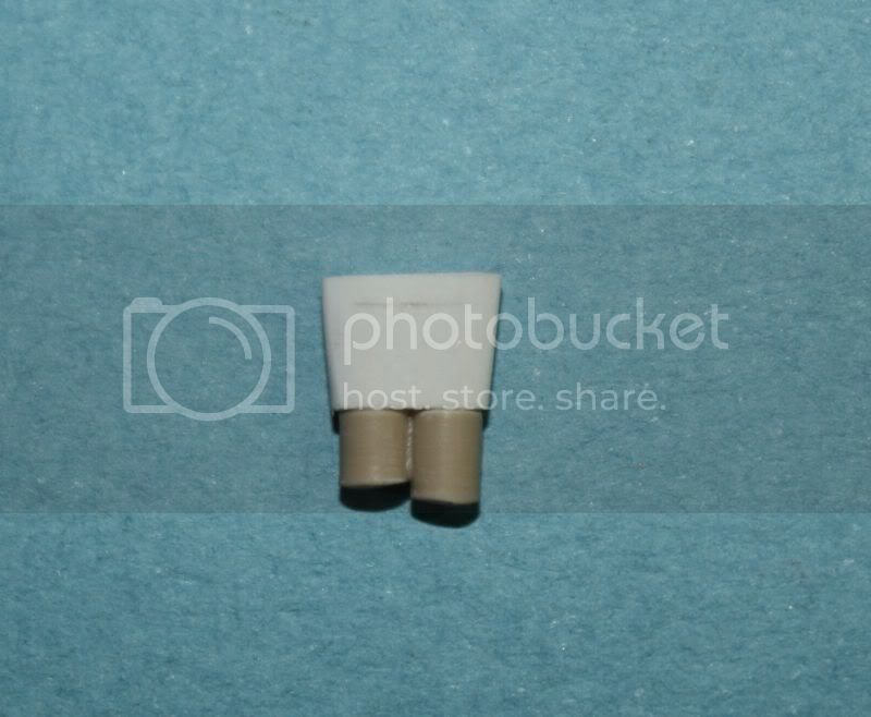
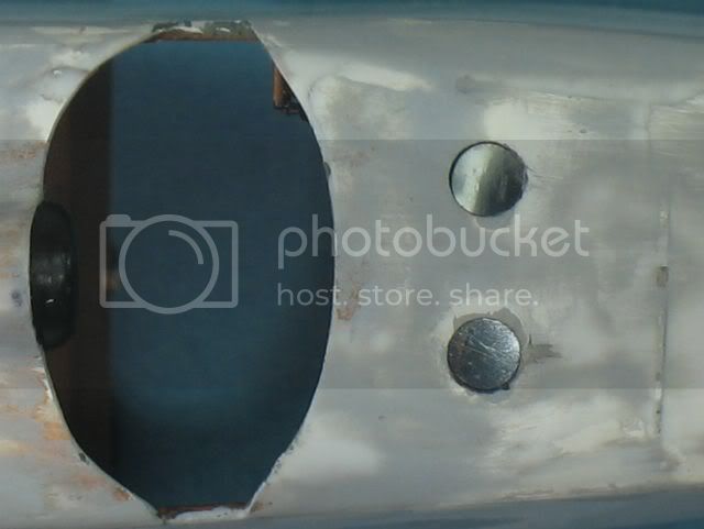
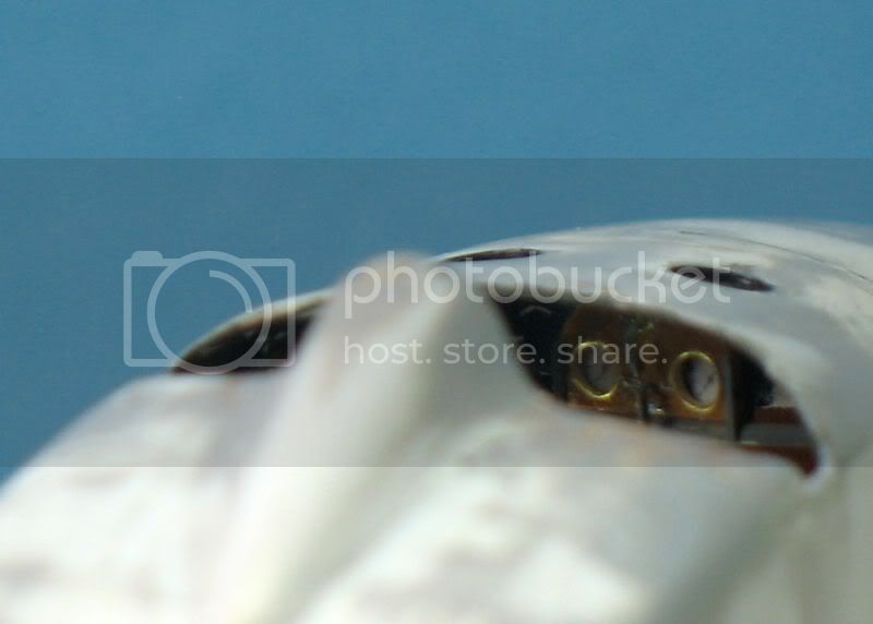
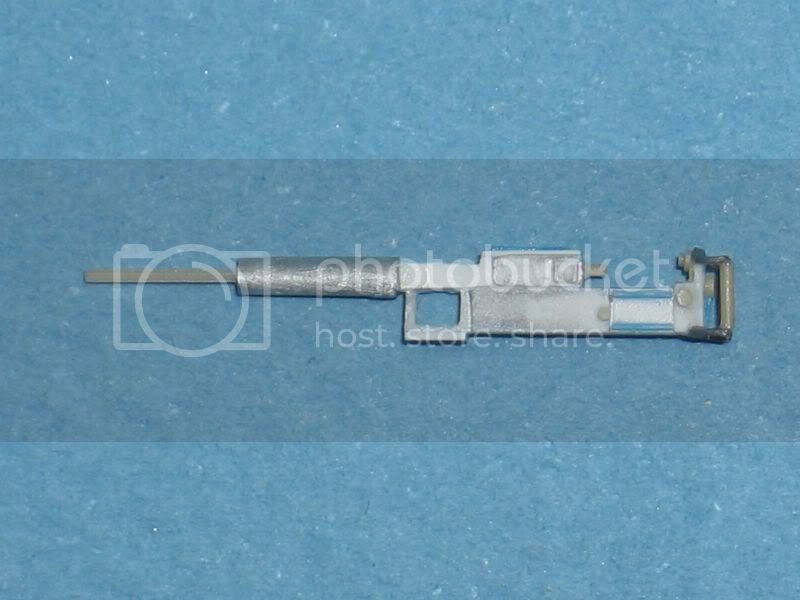
Only the rear will be visible. The cooling jacket and the gun will be hidden in the cabin.
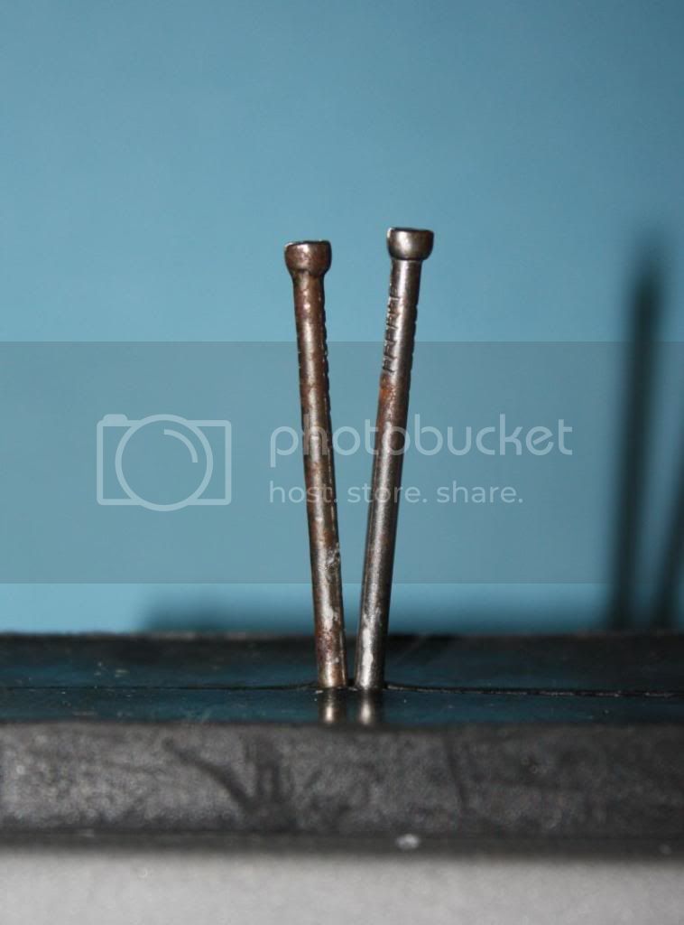
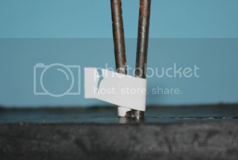
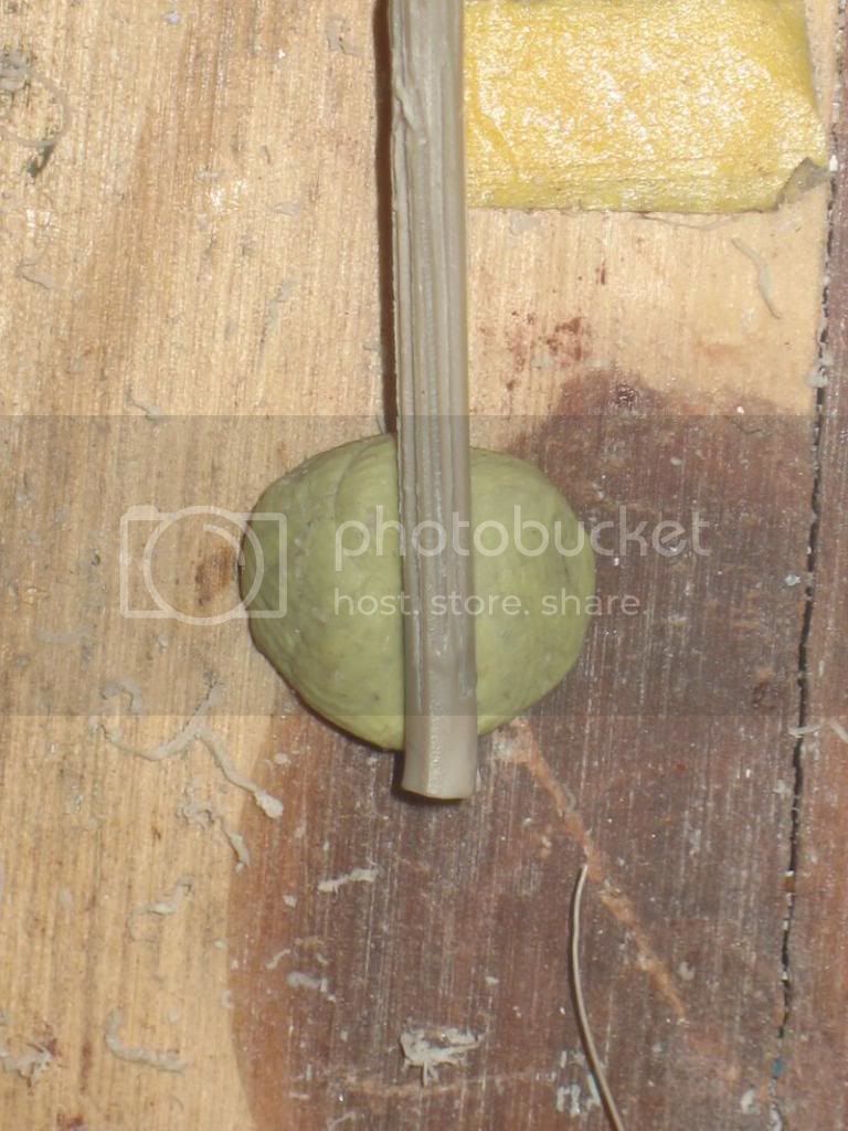
The rest of the handle are made with a tin wire formatted by wrapping around a rod and flat on a glass plate with a steel ruler. It's fragile but quickly made.

The support handle is made with a tin wire formatted by wrapping around a rod and then flattened on a glass plate with a steel ruler. It's fragile but quickly made.

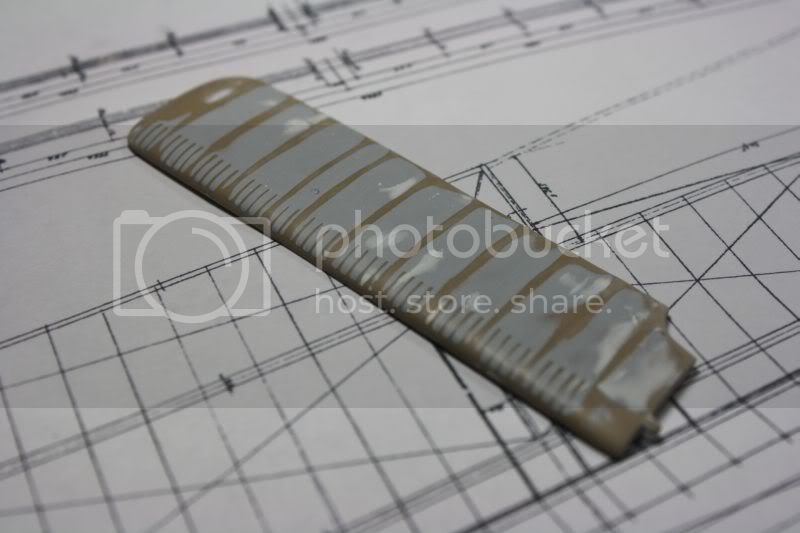
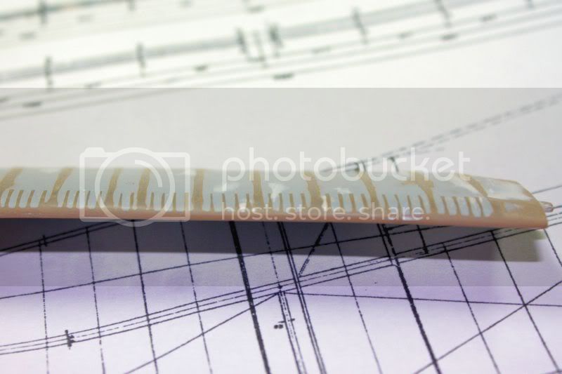
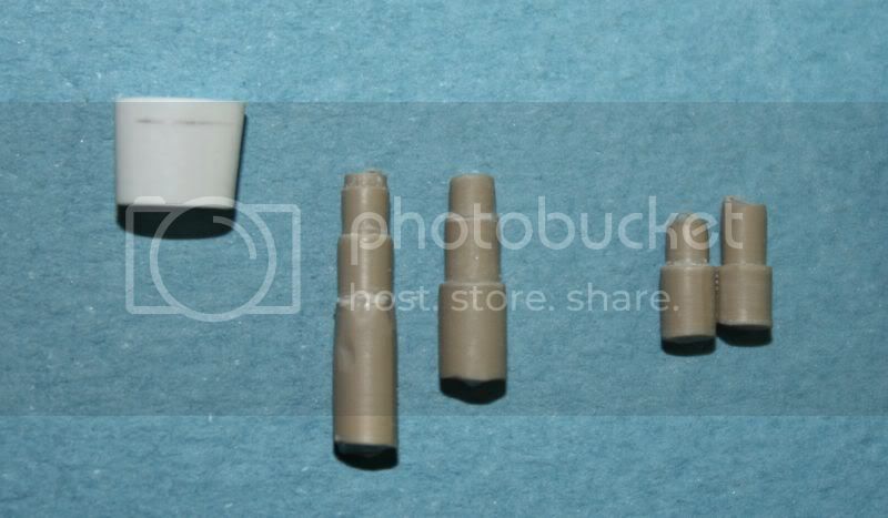
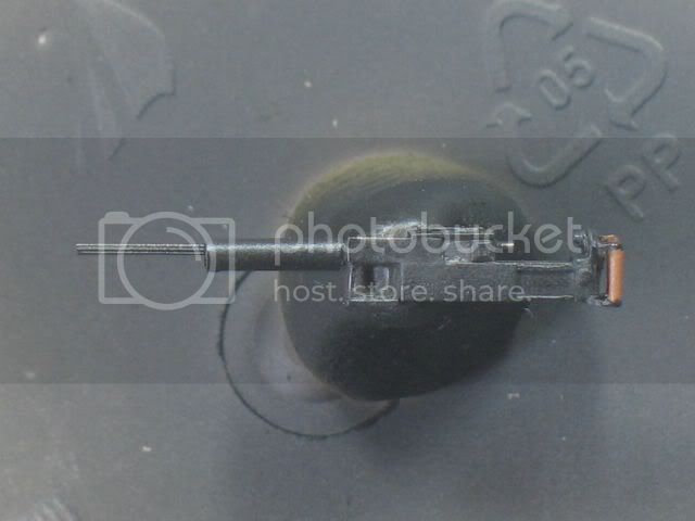
The barrel is made of plastic stretched. The piece is striated with very deep stria before being stretched. We find the stria after the plastic stretched. you dont see on the pictures because too thin.

before:


other files on other weapons:

http://www.smallarmsreview.com/Sample_Articles.htm


A +

Best regards

Louis
_VISITCOMMUNITY
Bas-Rhin, France
Joined: May 21, 2006
KitMaker: 472 posts
AeroScale: 471 posts
Posted: Saturday, September 25, 2010 - 04:31 AM UTC
The cooling jacket and the barrel have moved...of course:


Best regards.
JackFlash
_VISITCOMMUNITY
Colorado, United States
Joined: January 25, 2004
KitMaker: 11,669 posts
AeroScale: 11,011 posts
Posted: Saturday, September 25, 2010 - 08:31 AM UTC
Nicely done Louis!
Louis
_VISITCOMMUNITY
Bas-Rhin, France
Joined: May 21, 2006
KitMaker: 472 posts
AeroScale: 471 posts
Posted: Wednesday, October 06, 2010 - 08:52 AM UTC
The ammunition box and boxes to gather spent cartridges and empty magazines:


The spent cartridges are ejected from the top of the gun and deflected to the right. There is no space between the hull side and the weapon on the right side of the cockpit. Probably I would not put the rectangular box to the right weapon.

Of course I am sure of anything ...

Regards
Roxter
_VISITCOMMUNITY
Rigas, Latvia
Joined: July 04, 2007
KitMaker: 268 posts
AeroScale: 245 posts
Posted: Wednesday, October 06, 2010 - 07:26 PM UTC
simplement magnifique! very informative and inspiring!
SGTJKJ
#041
_VISITCOMMUNITY
Kobenhavn, Denmark
Joined: July 20, 2006
KitMaker: 10,069 posts
AeroScale: 3,788 posts
Posted: Thursday, October 07, 2010 - 02:29 AM UTC
Great progress, Louis. You really get the details right and it shows.

Looking forward to see more
thegirl
_VISITCOMMUNITY
Alberta, Canada
Joined: January 19, 2008
KitMaker: 6,743 posts
AeroScale: 6,151 posts
Posted: Thursday, October 07, 2010 - 02:19 PM UTC
Excellent progress Louis , I always look forward to your up-dates !
Louis
_VISITCOMMUNITY
Bas-Rhin, France
Joined: May 21, 2006
KitMaker: 472 posts
AeroScale: 471 posts
Posted: Friday, October 15, 2010 - 07:34 AM UTC

Merci, Thank you.

The new Macchi M5 from Blue Max:


http://www.hyperscale.com/2010/reviews/kits/bluemaxmacchim5preview_1.htm

Regards.
Greenonions
_VISITCOMMUNITY
United Kingdom
Joined: February 26, 2010
KitMaker: 74 posts
AeroScale: 71 posts
Posted: Friday, October 15, 2010 - 09:28 AM UTC
Only 300 hundred kits available world wide?Are there so few of us that covert this little gem?
Louis
_VISITCOMMUNITY
Bas-Rhin, France
Joined: May 21, 2006
KitMaker: 472 posts
AeroScale: 471 posts
Posted: Thursday, October 21, 2010 - 11:53 PM UTC
Hello,

The holes are drilled for windows, 2.5 mm, which are now almost 3mm after sanding. They are a little too large and a bit too far apart from each other.


The deck is sanded as possible and the windows are installed inside the cockpit. They are a bit too deep compared to the bridge surface. Transparent plastic glued and sanded and then polished would have, I think, a better result but my deck is too thin and too fragile.


The gun is cutted (almost in 2 part...) to fit into the cockpit. dont forget the small climb indicator on the left.


Regards.