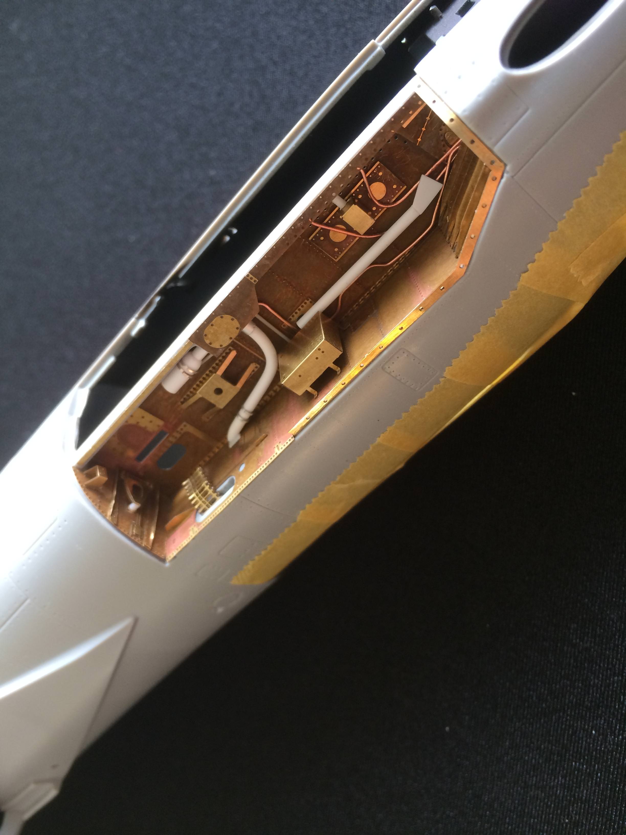
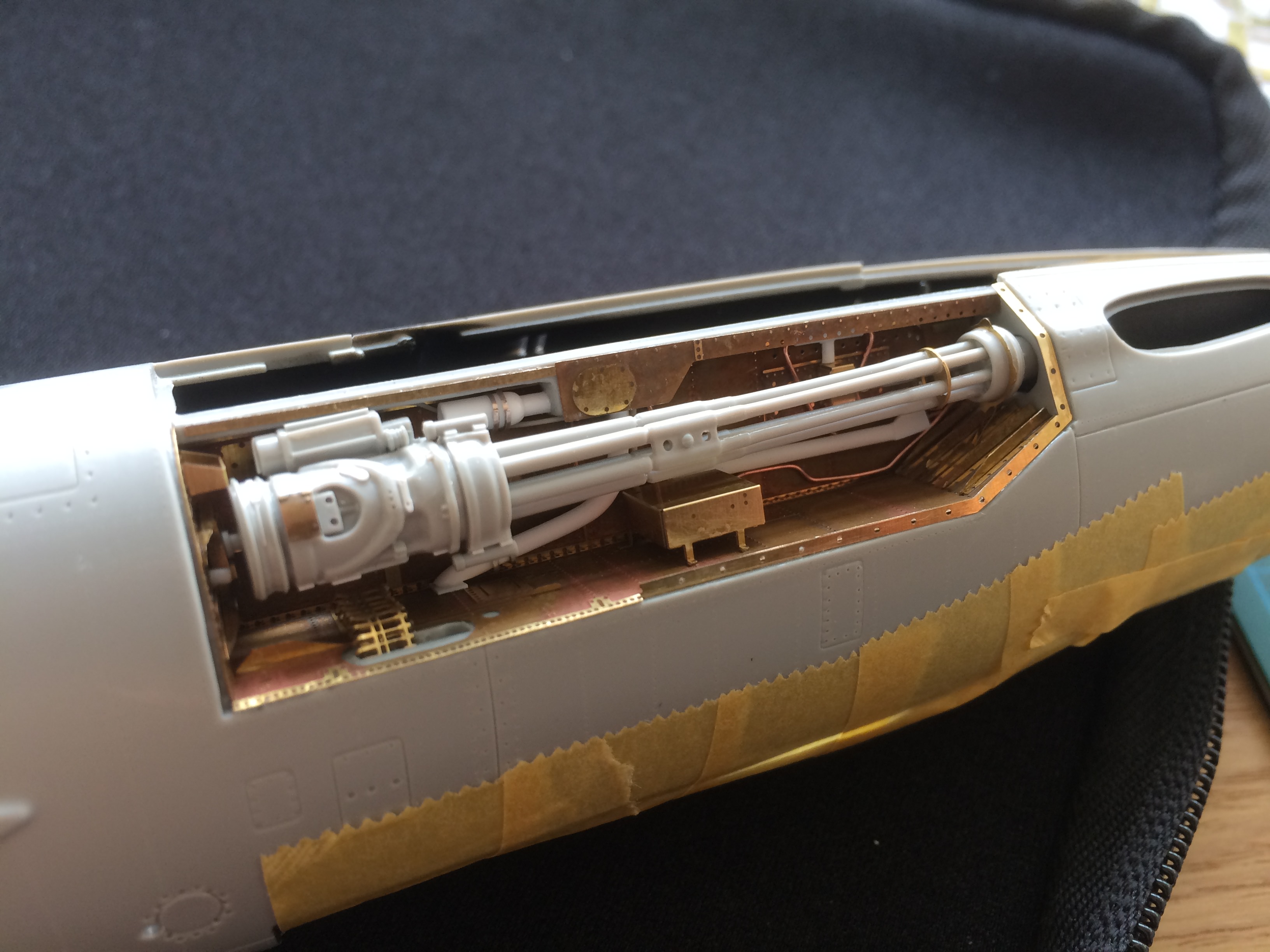
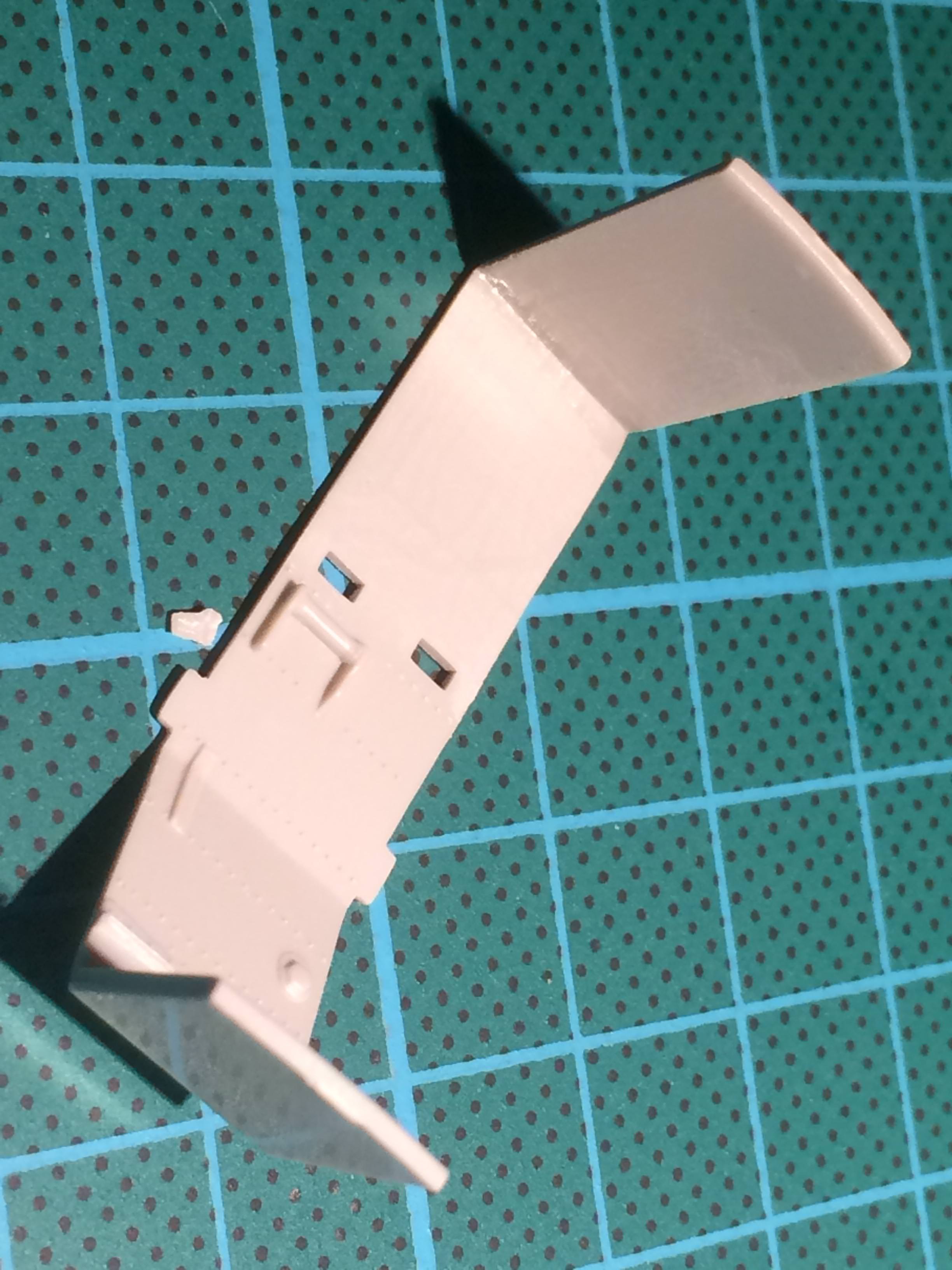
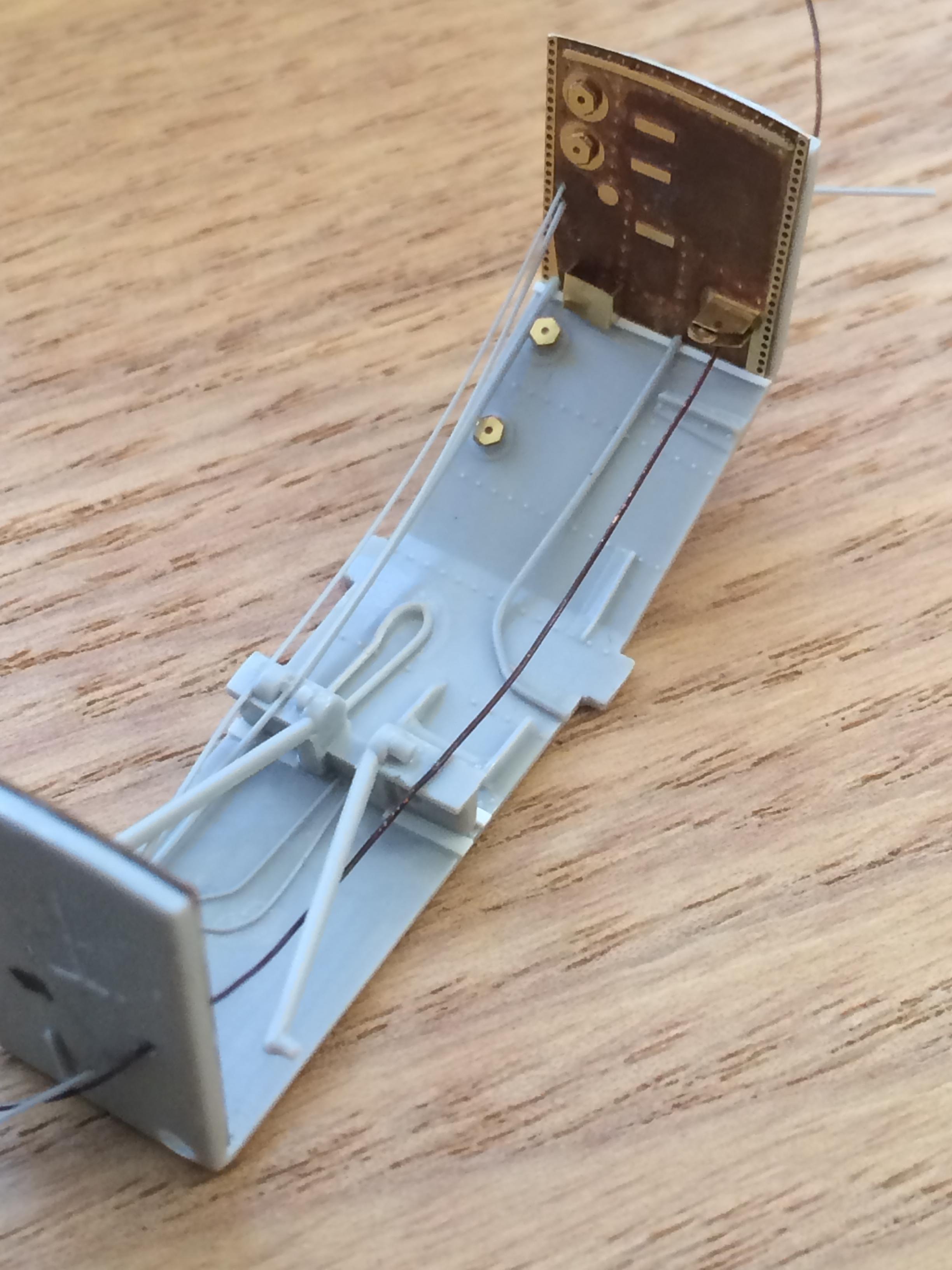
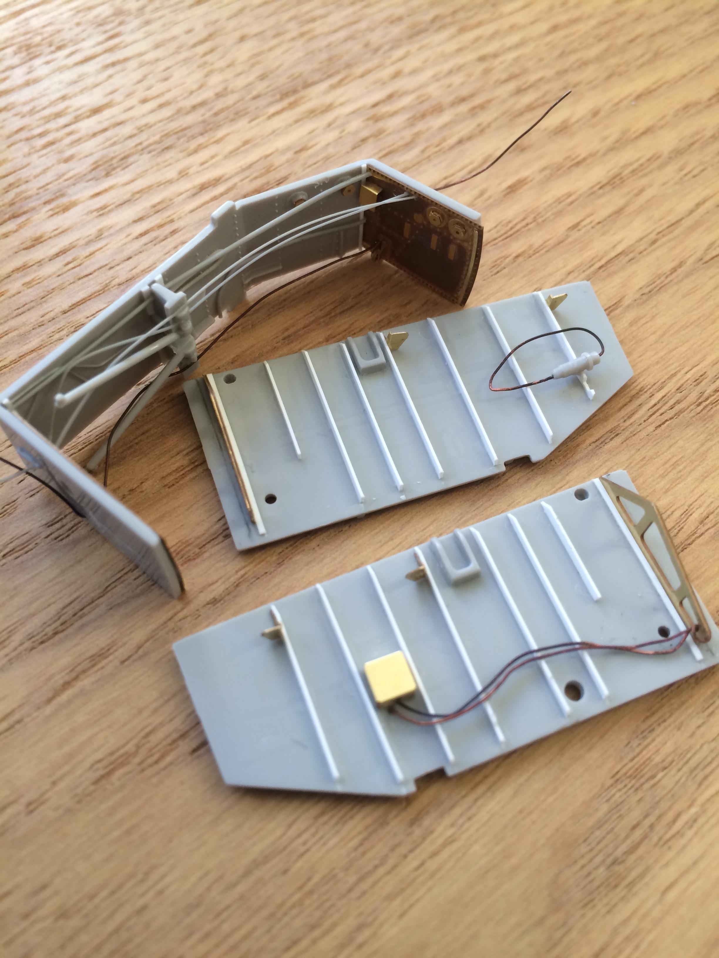
Ladies and gentleman, I present the next step - the front landing gear and wheel bay. The approach is the same as that taken for the rear. Im removing softly moulded detail so I can replace it with better PE or scratch built parts. The one exception is the roof of the wheel bay. This area is deeply recessed in the model and will be partly covered by other components so Im living with the basic detail.
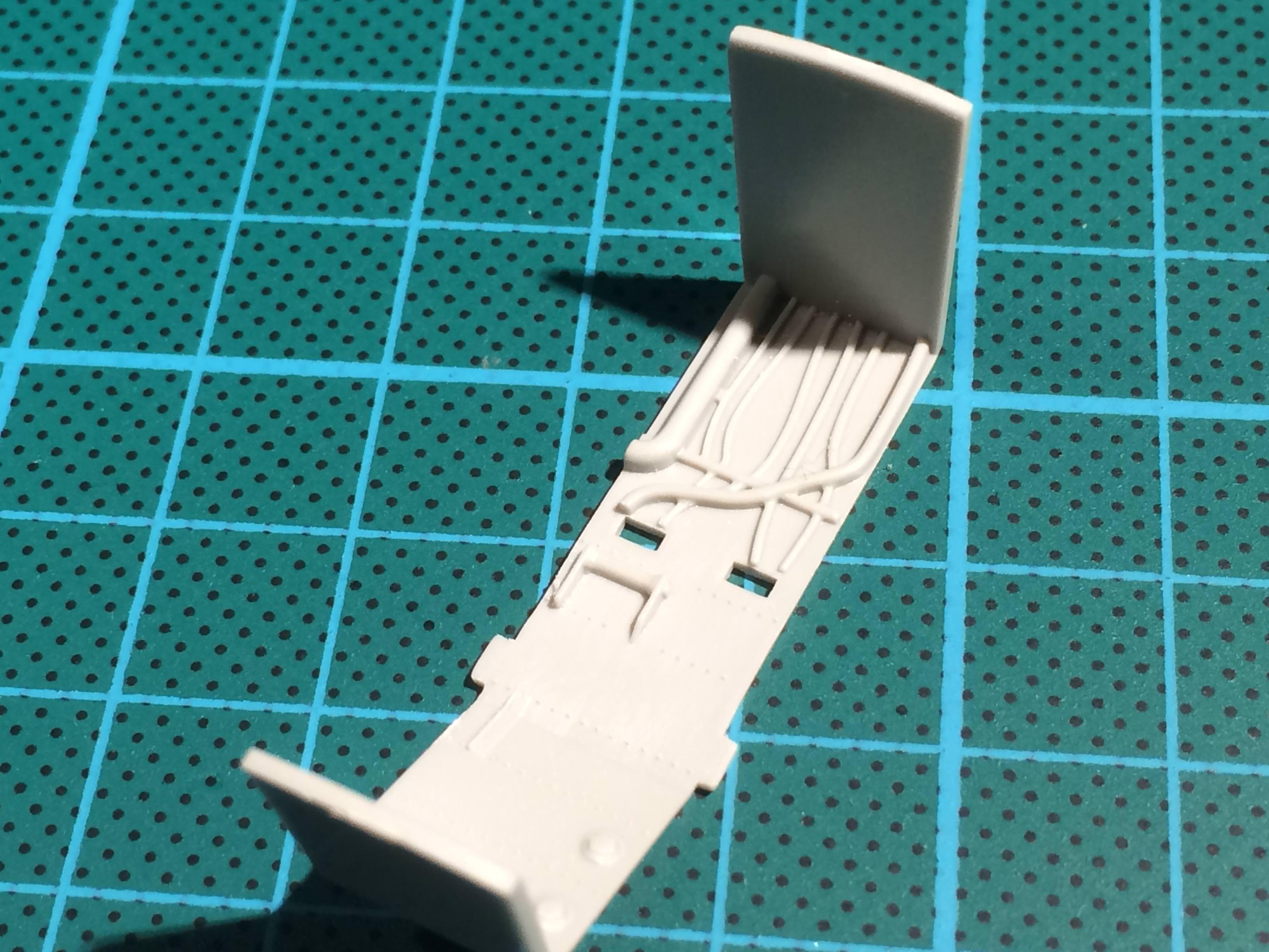
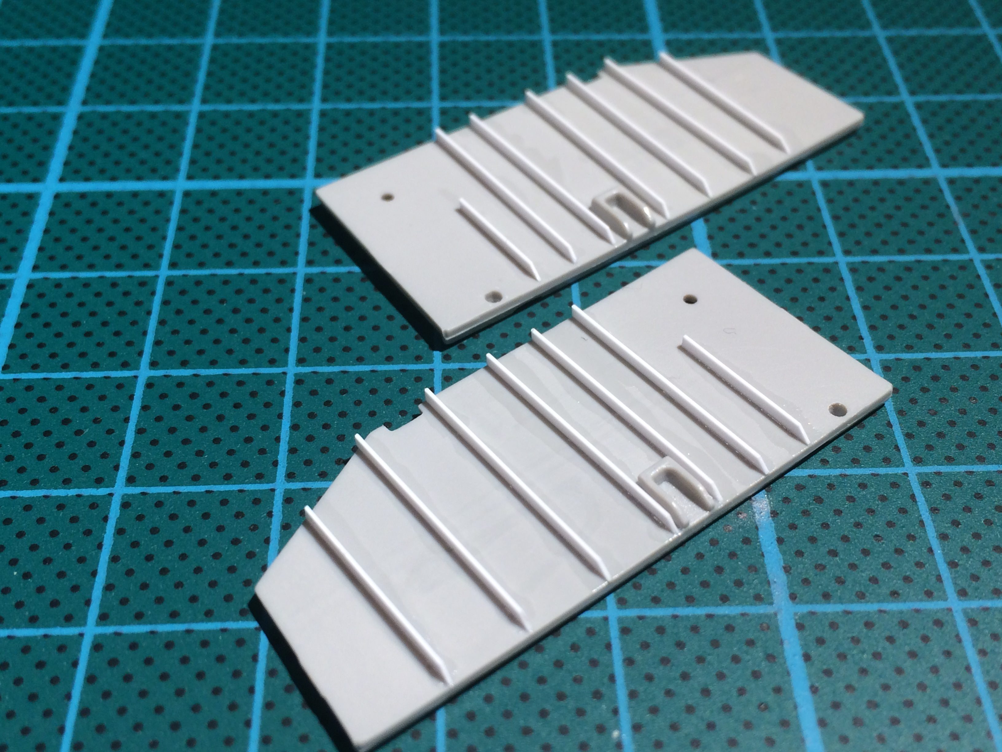
The side walls are not so lucky and had the attention of scalpel, chisel and sand paper. Here we go
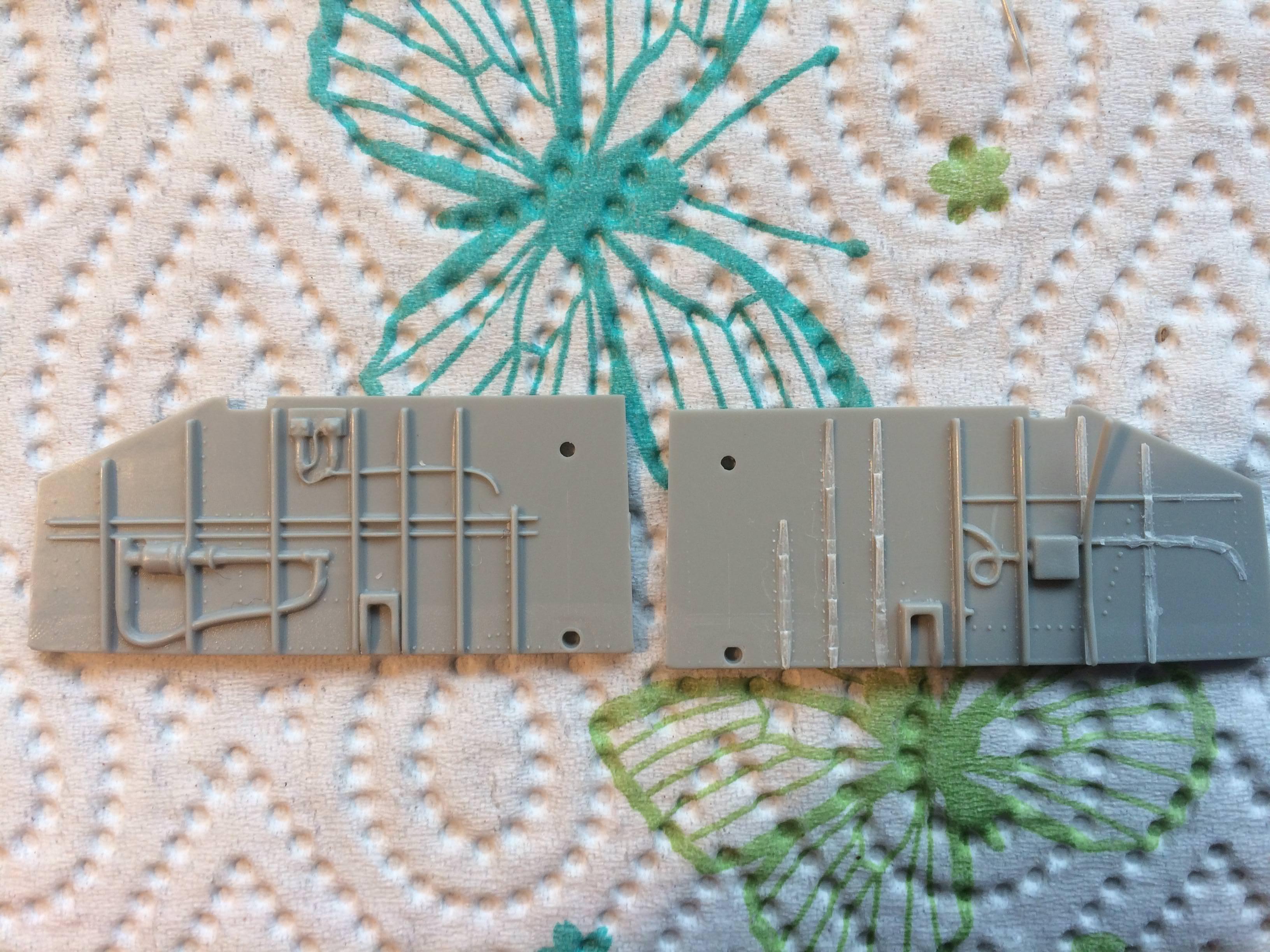
By the way, I took a photo of the original part to keep as a reference. In the process I stumbled on a nifty technique to take a life size shot so the photo is a sort of blue print. It only works with parts that are mirrored like the sidewalls here. With the camera on, I put one part on the screen of my phone and then prepared to take a shot of the other. By zooming or moving the phone I could get the subject perfectly covered by the first part sitting on my phone screen. Snap, et voila - a life size shot. Now I have something to help me get the details in the right position (or not if they were wrong to start with).
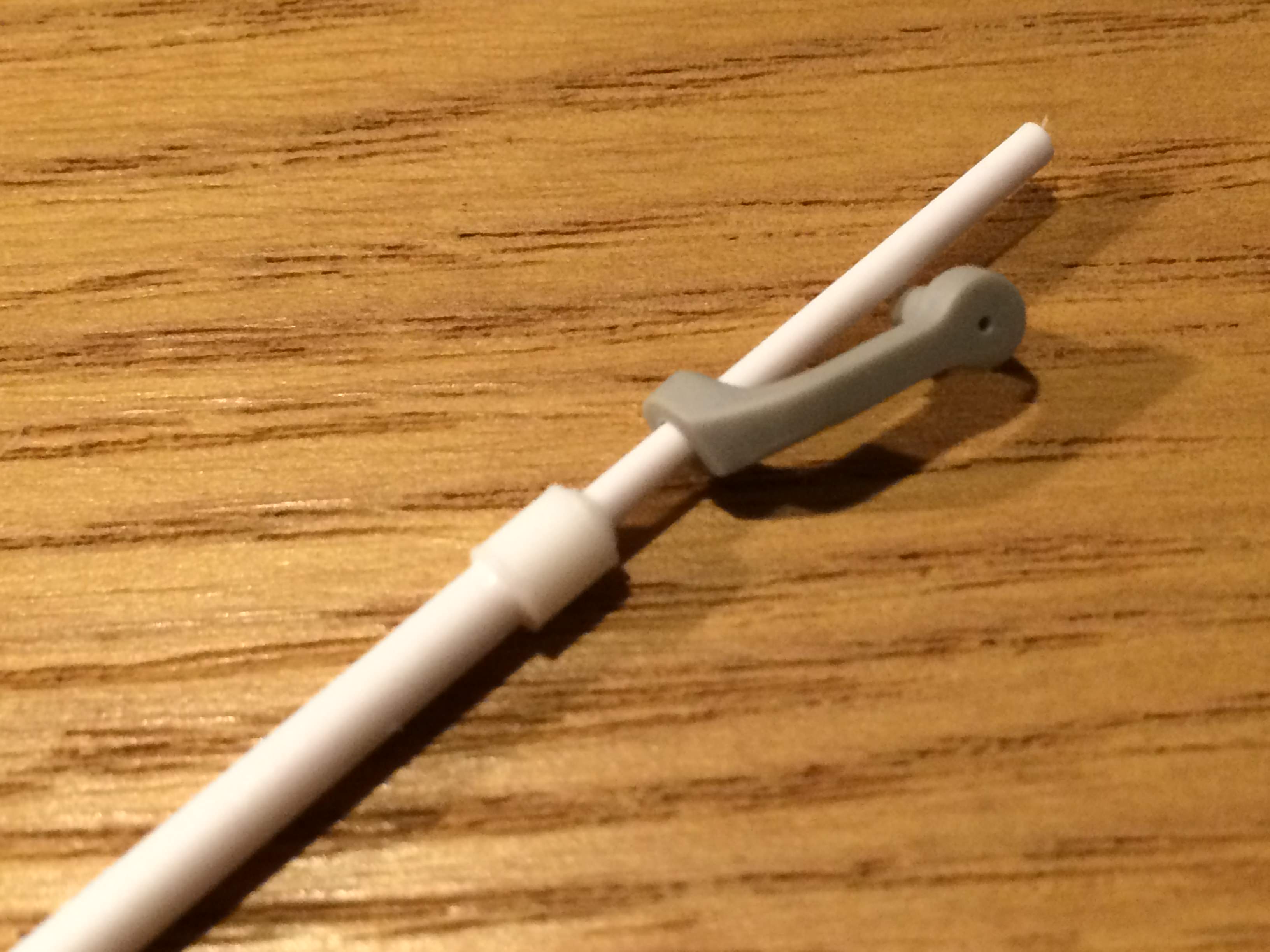
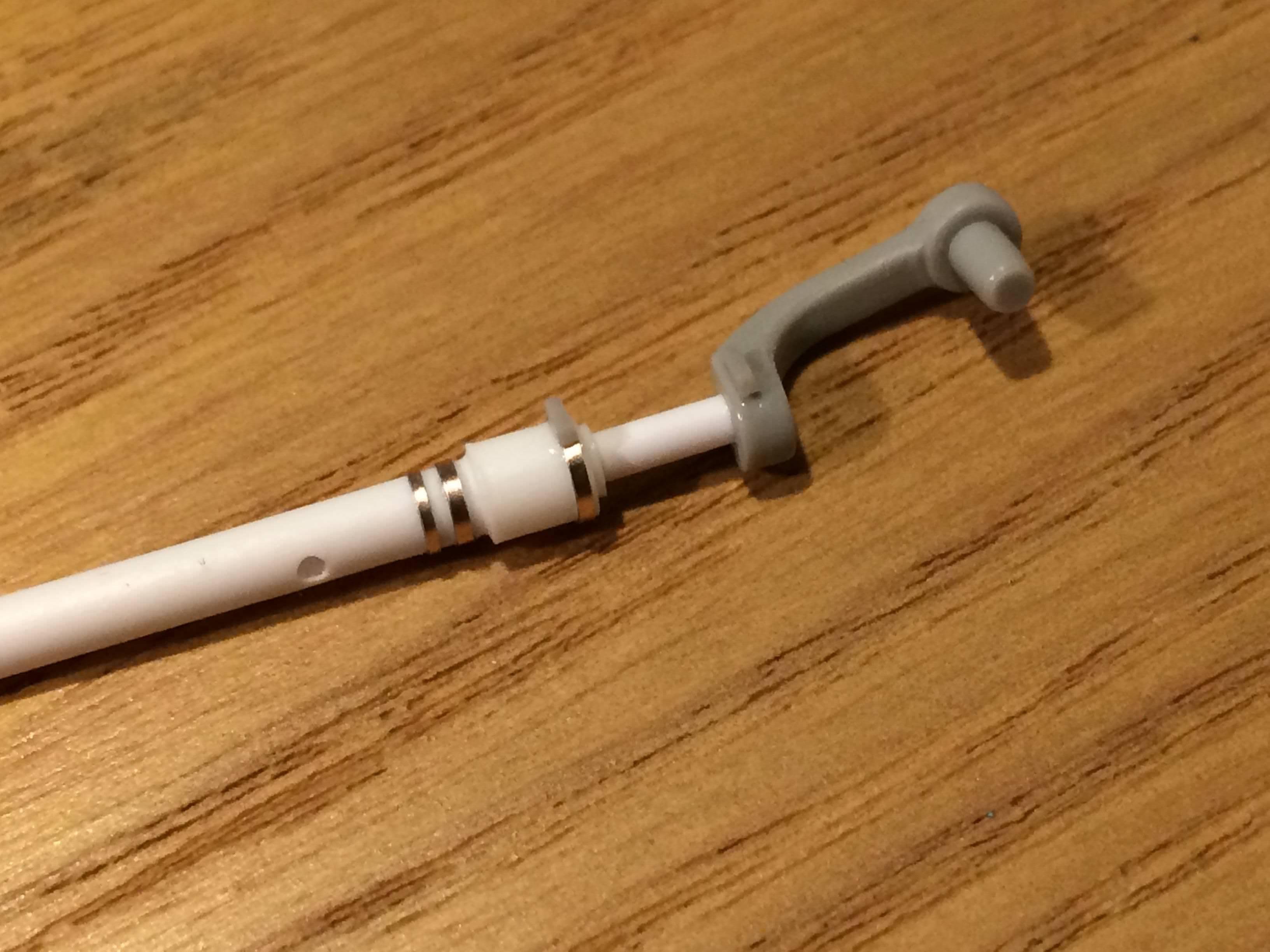
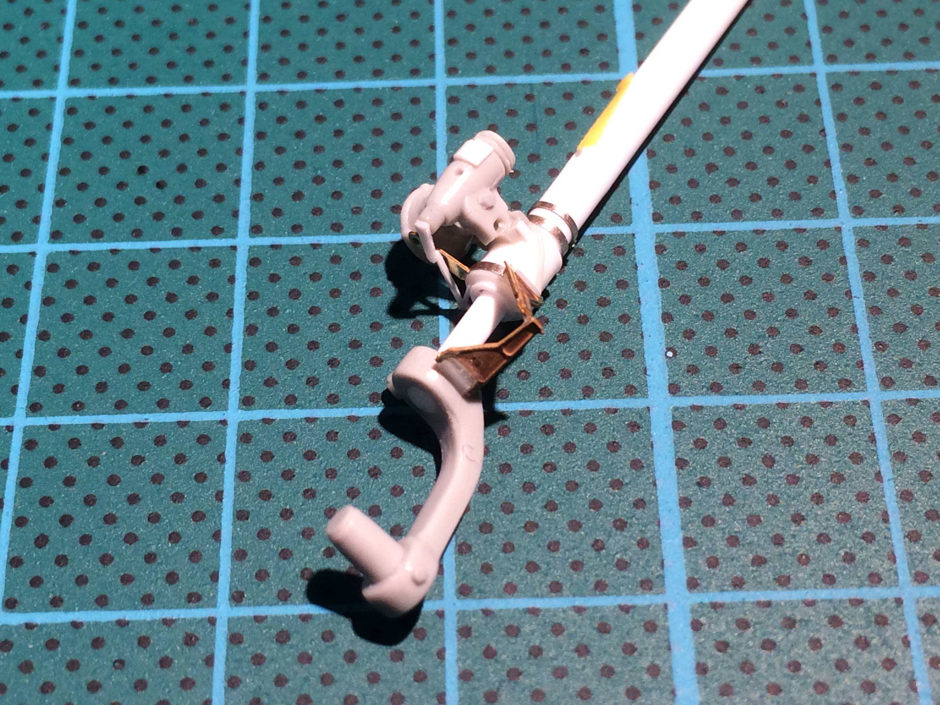
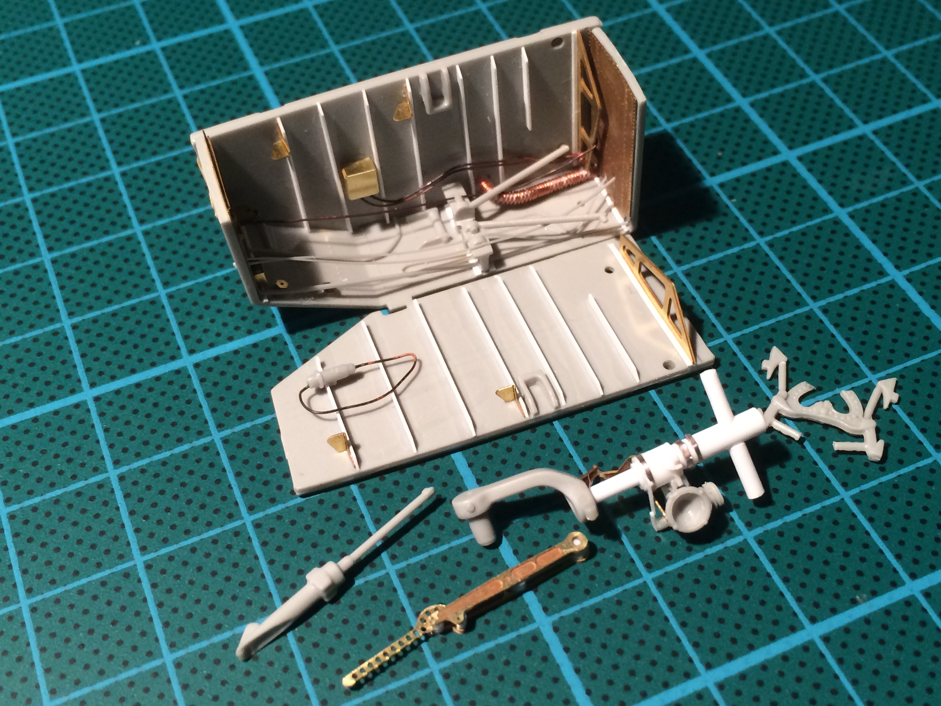
The landing gear strut is not one of Italeris finest works. The detail is very soft. There are also heavy bur lines and a deepish ejector pin mark. I looked and thought Nope. Its got to go. Scratch building a new one is pretty simple (or at least it feels that way now I have some practice under my belt). The basic components are plastic strip in three diameters. Im sorry but I dont know the exact measurements - I just rummaged about until I found pieces that were the same diameter as the basic parts of the strut.
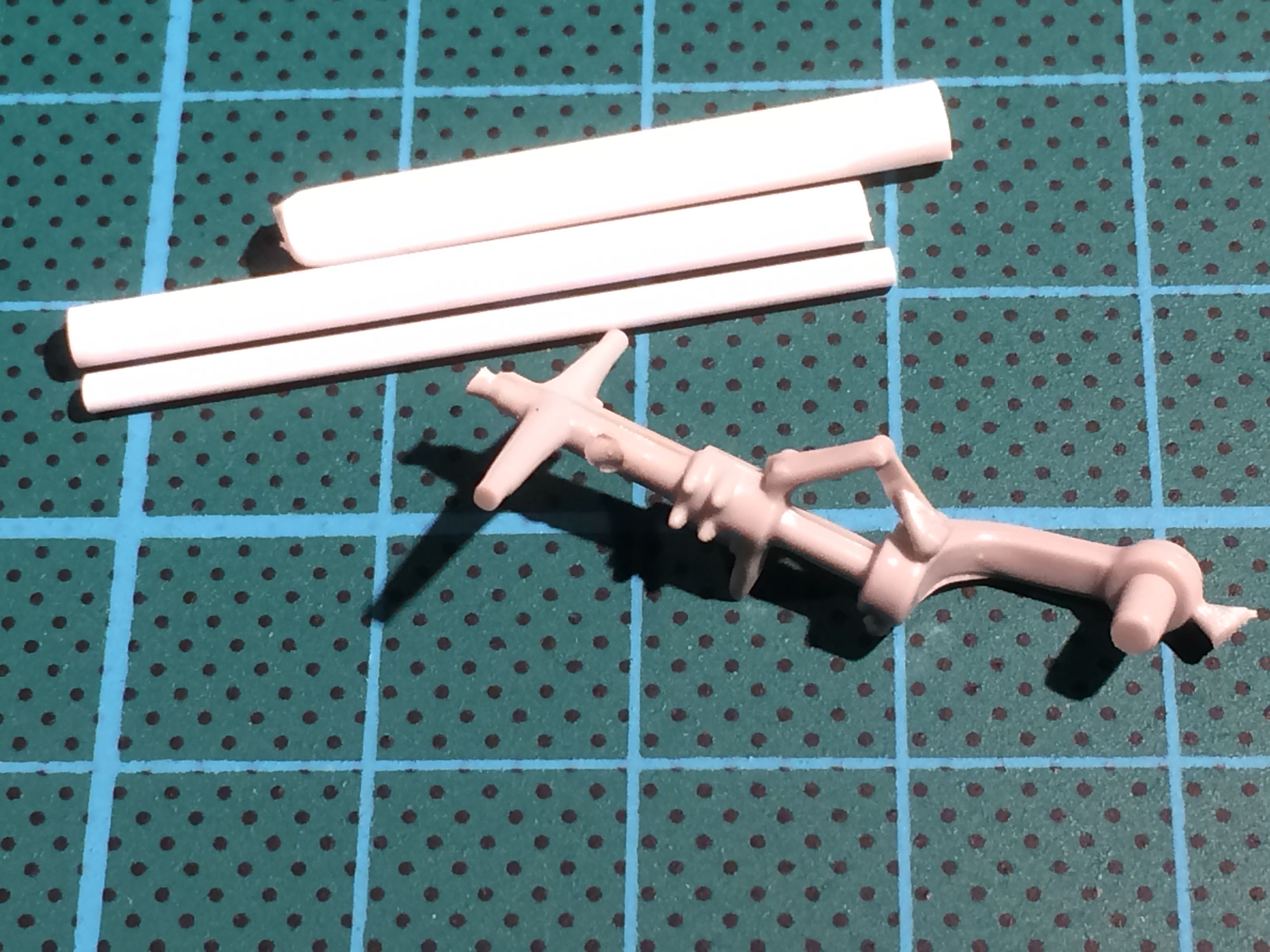
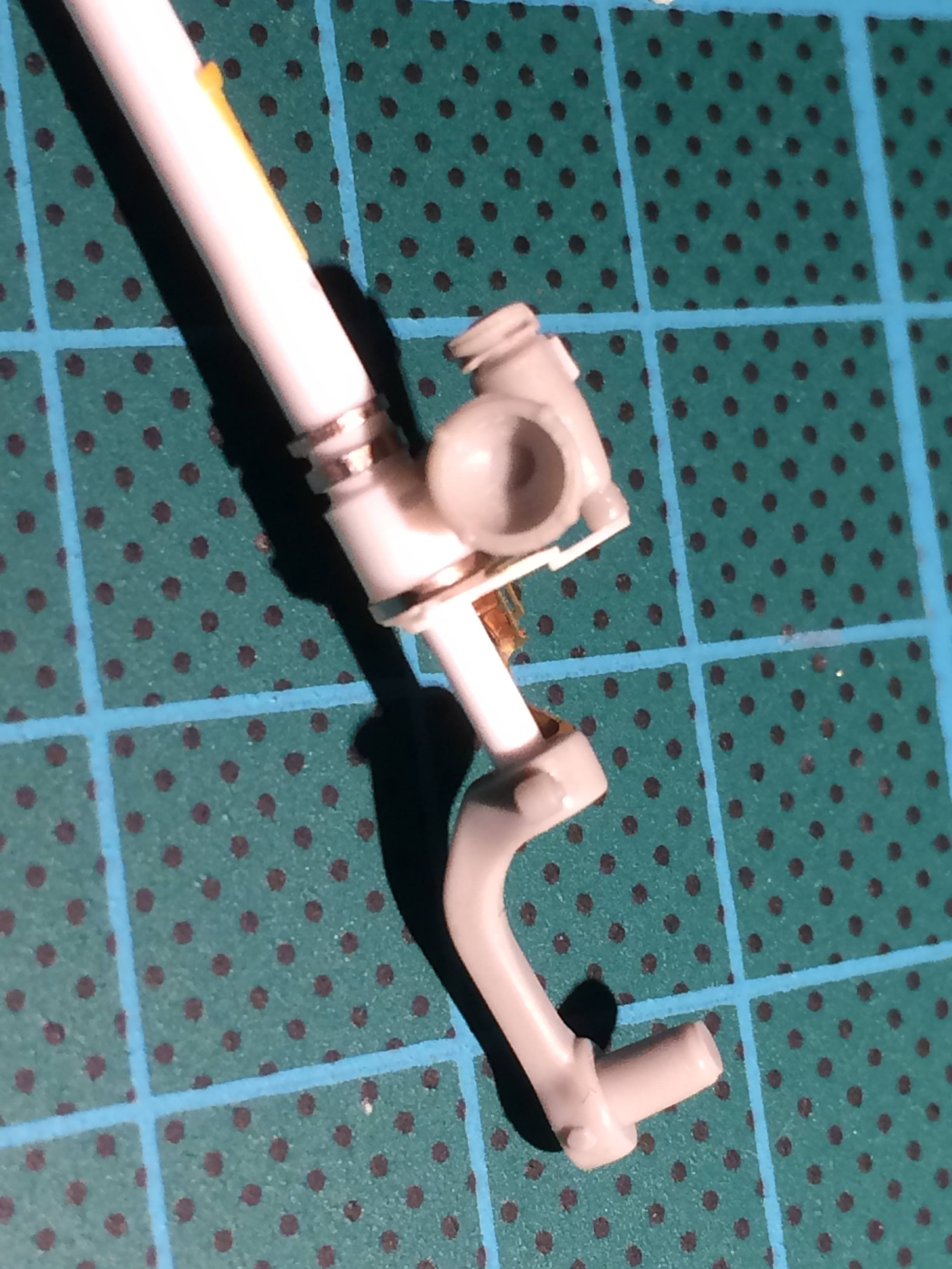
First I drilled out the centre of the larger rods to match the diameter of the inner piston (the bit that does the sliding in and out on the real thing). Then I cut a larger ring at the base to the right size and slipped it over the piston. Next the upper thinner diameter part was slipped on. Crikey, there were more things sliding in more places than a dodgy movie, and the end result was more satisfying.
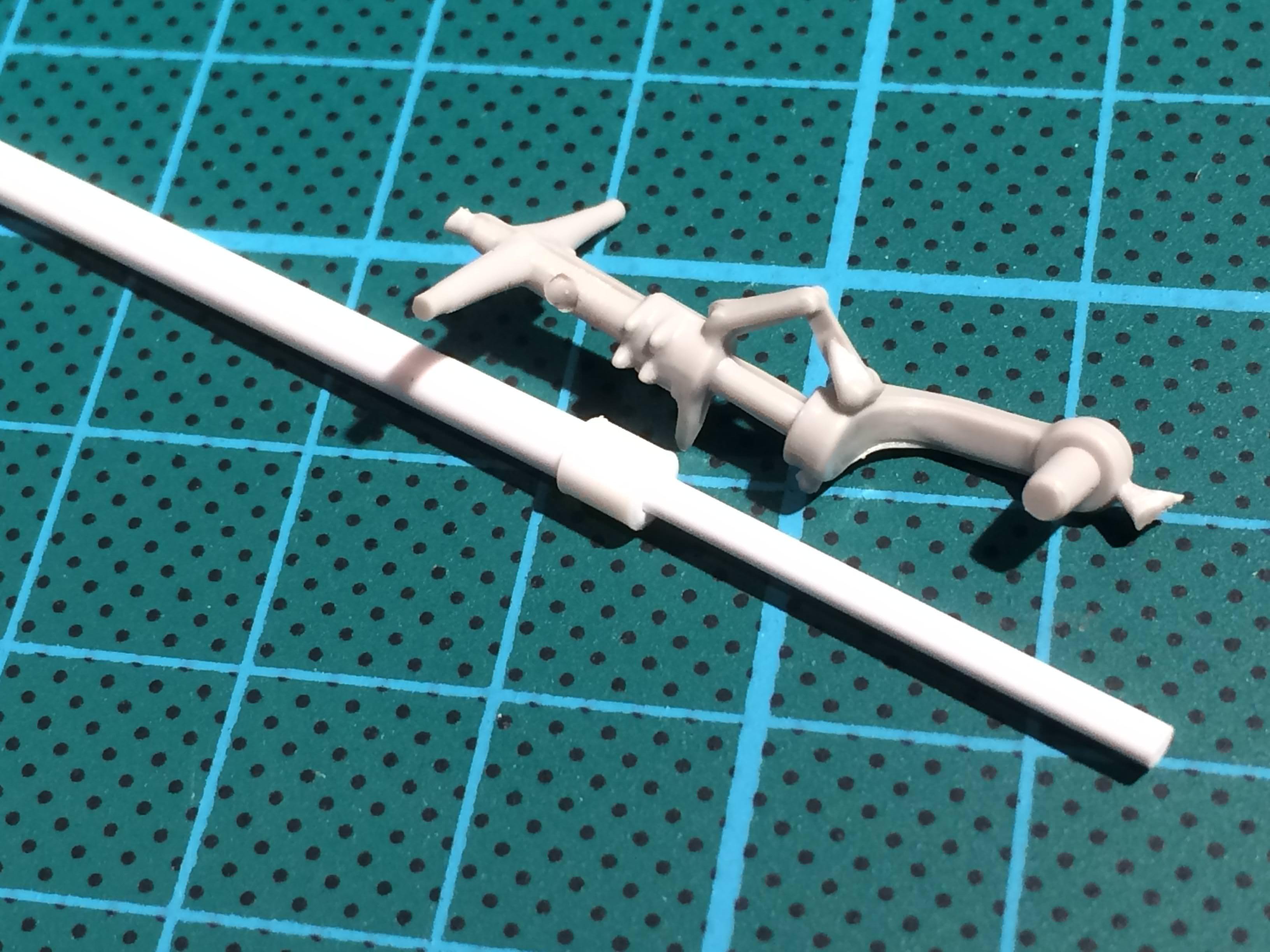
If I had it to hand I would have used brass rod for the inner piston, simply to add strength, but I dont have the right size. I did a little test and these short sections of plastic rod should be strong enough, especially with the core all one piece. Fingers crossed it all works out.
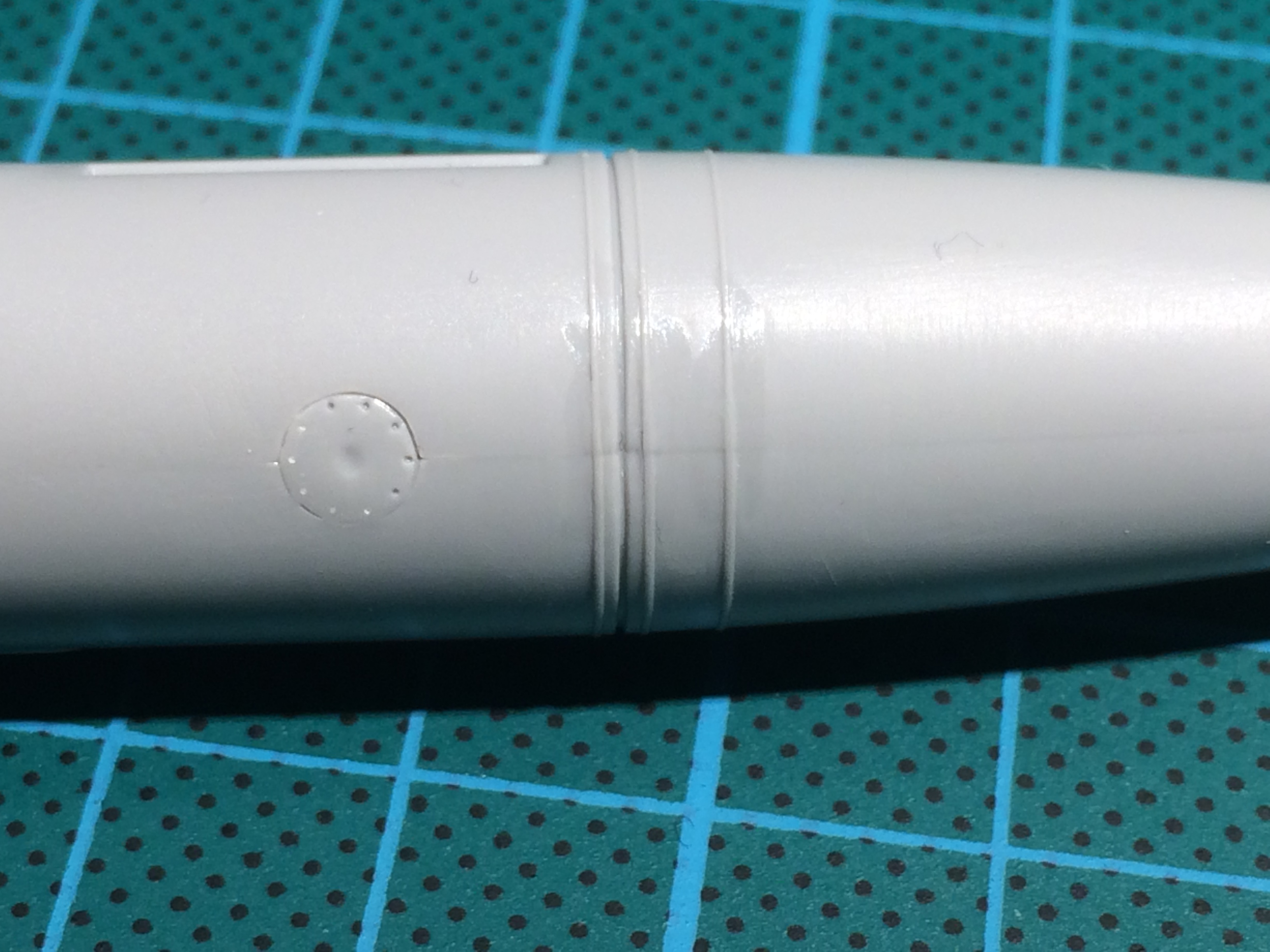
I started working on some extra details by slicing thin segments of rod. Its hard to get a consistent diameter but perseverance paid off in the end. These are the rejects.
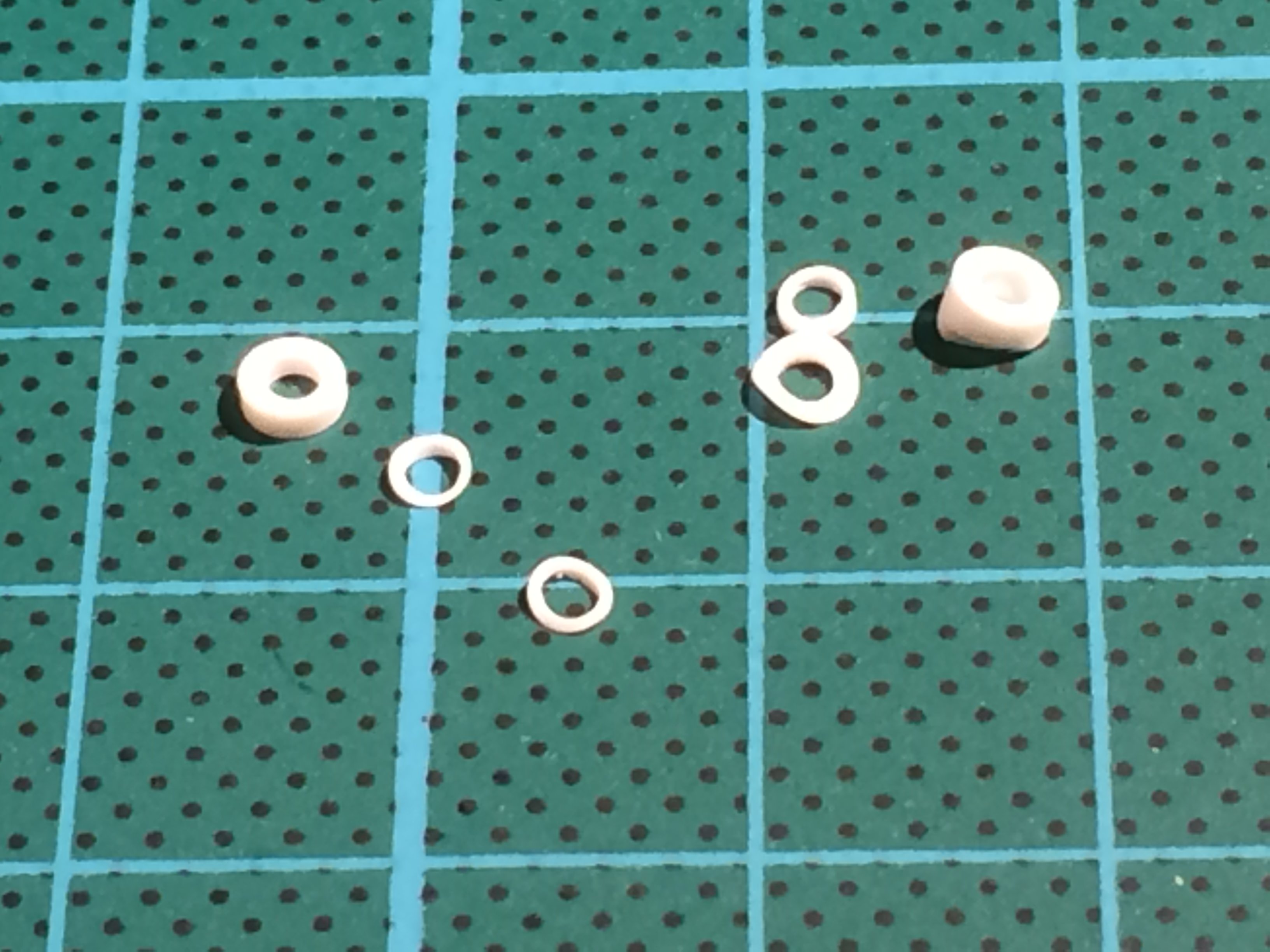
So far so good.
Happy modelling guys.