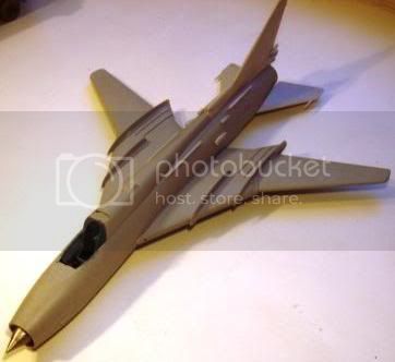
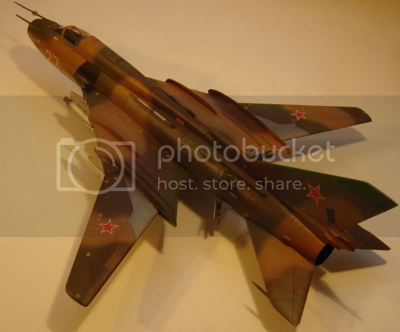
Pigsty again with that Flogger.
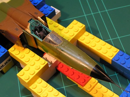
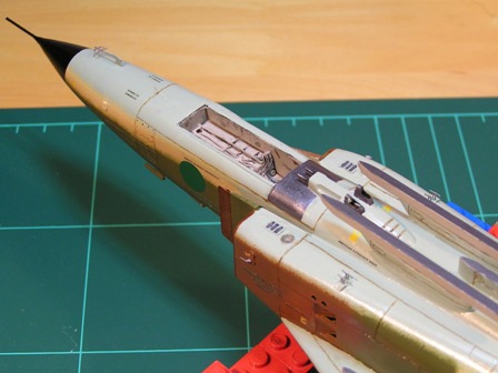
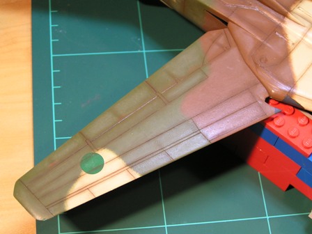
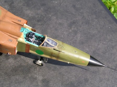
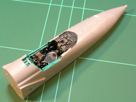
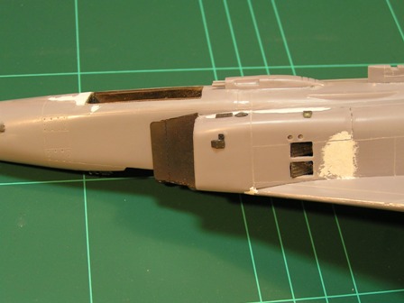
Here's the forward fuselage assembled, with the cockpit installed. Again, the instructions failed utterly to help. I had to work out the hard way that much more of the kit parts had to be cut away than was set out, which took some time. At this point theres no nose weight inside, which was a mistake. Luckily resin is quite heavy. The work round the radome junction is fairly obvious: I think both were roughly circular, but with different radii, so there were gaps and bumps at the same time, but its mostly OK now.
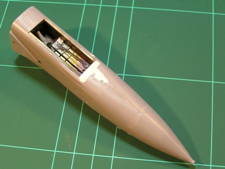
This is the nosegear well
in situ. Note, again, filler, plus filler, plus filler. This is partly because the well has to be moved back slightly and partly because, this time, Eduards instructions werent abundantly clear.
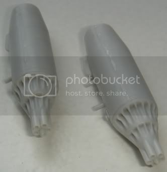
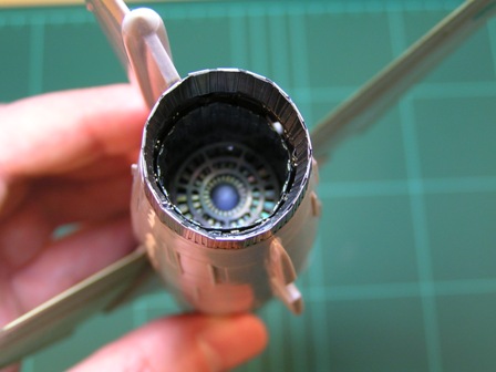
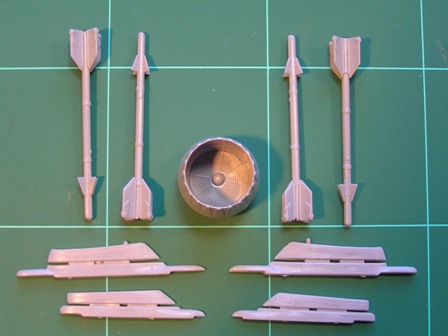
That PE afterburner and exhaust. This time its not Eduards fault that its not quite round. The turbine centrebody is the nose off one of the kits R-23s. All theyre good for, really. How Im to paint all this defeats me.
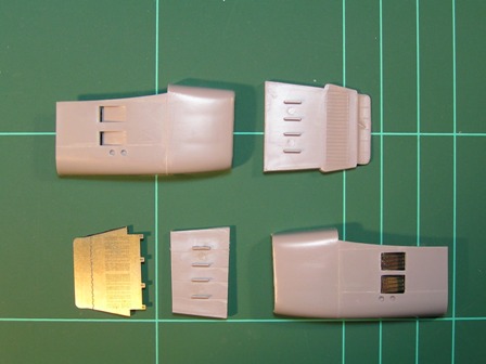
The intakes before (top) and after (bottom) Eduard gives you the blow-in doors, which again take some fitting, and the splitter plate. Theres a lot of thinning to do here. The full horror of fitting the intakes comes later. I've dry-fitted them and it's not looking good ...
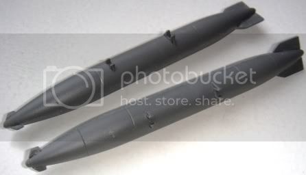
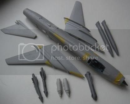
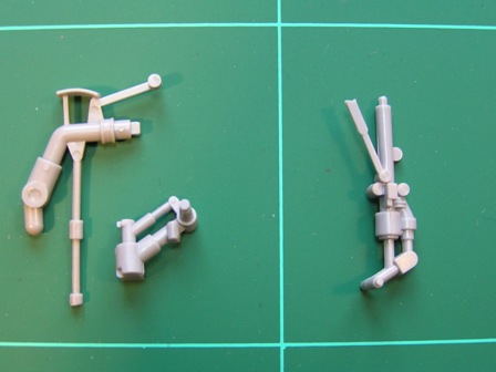
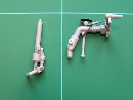
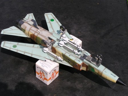
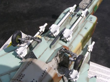
A miscellany: the kit exhaust, to show you how poor it is; the kit pylons; and four AIM-9Bs (from Hasegawas Weapons Set C) about to defect and become R-3s (AA-2 in old money). Theyre close enough to be acceptable more accurate than either of the kits missiles, anyway. At this point Ive drilled out the missile exhausts and painted them black, but not scribed the panel lines on the pylons.
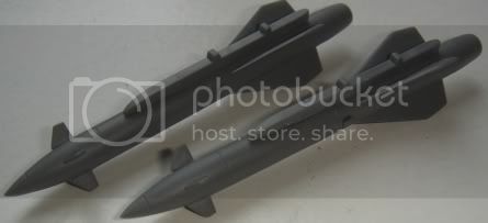
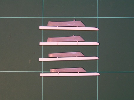
The pylons with R-3 rails. An easy job square plastic rod, appropriately profiled, and dont worry too much about panel details.
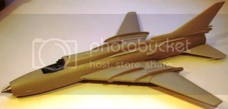
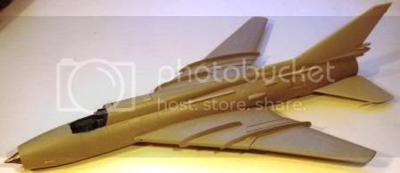
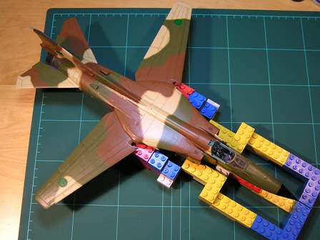
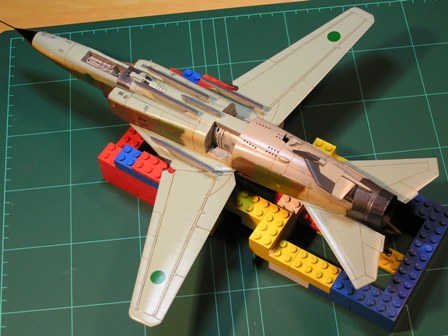
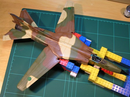
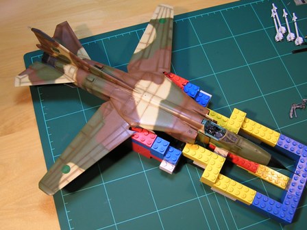
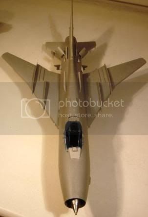
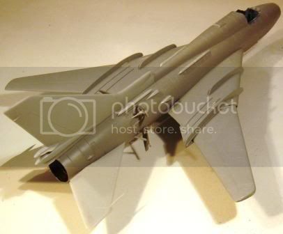
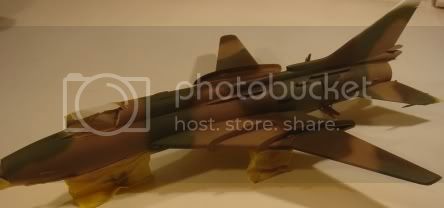
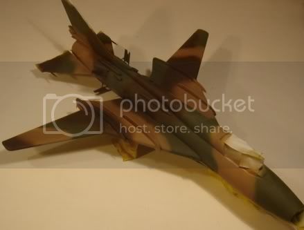
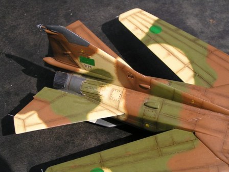
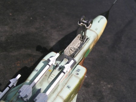
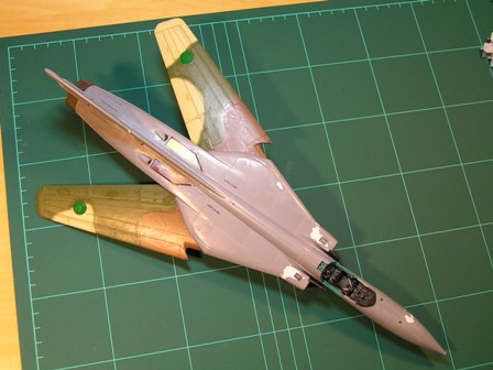
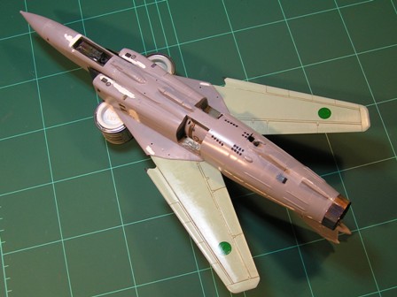
And here's the fuselage assembled, including the intakes and splitters, plus all the surface PE that wont pop off at the sight of a paintbrush. Now you can see all the filler: all the way along the fin root (you have to thin the locating tab to get it in, then youre left with this); all along the rear fuselage top-bottom joint; and all around the intakes, and its not finished there yet. The problem with the fuselage is that the top half is slightly narrower than the bottom. If I were doing this again (as if!), I might insert a spreader bar and hope it didnt distort the exhaust opening. There are holes drilled in the fuselage pylon mounts to take plastic pins sunk into the pylons. This is because theyd be butt-jointed otherwise, and its so crowded down there that theyd be bound to fall off.
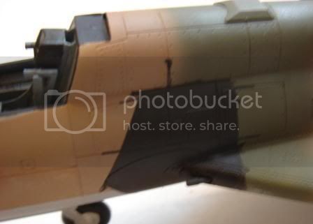
Talking of butt-joints
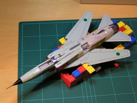
when Esci designed the kit they gave it separate noses for the MiG-23 and MiG-27 (good) and made them butt joints (less good). So, he thinks, lets help it out with some plastic pegs. Drill one side, mount little lengths of plastic rod all fine so far; measure up where the ends of the pegs go, drill the other side; and do they match? Do they buggery. So after some considerable routing out, they fit just poorly enough to leave some sanding to match up the fuselage contours on either side of the joint. But it is a strong joint. I know this because I managed to slam the nose down on the desk and nothing happened.
At this point I
have now installed nose weight. I cut up fishing weights, as I normally do; and had to feed them in through the mounting slots for the intakes, which was a bit of a departure. Once there seem to be enough in, you flood the hole with super-glue. Then the model rattles for a few days as the loose ones run around and eventually make their way out through gaps you didnt know existed. Caught them all, though.
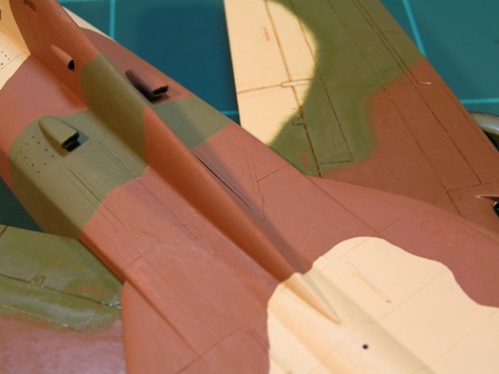
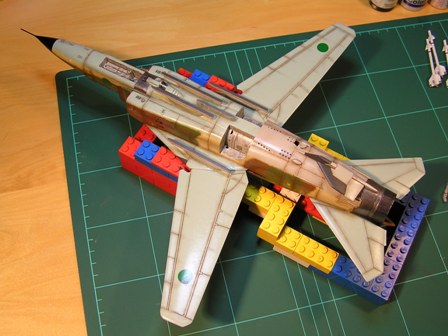
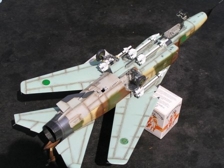
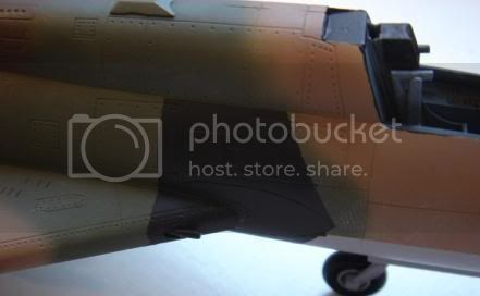
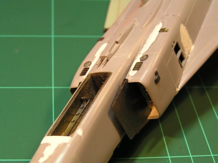
Close-ups of the intakes for the full horror. Basically, they were the right shape, but the wrong scale too narrow all the way round. The Eduard splitter plates are wonderful, though. That one of them is sitting on spacers is Escis fault, not Eduards.
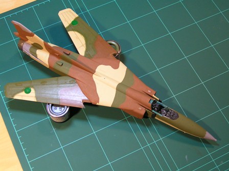
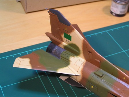
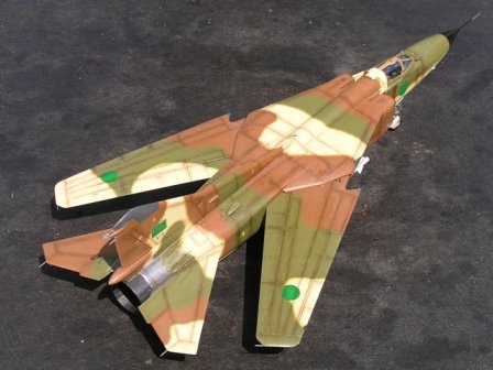
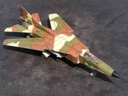
Getting there ...