Jessica-
I am glad to hear that the parcel made it to you. Obviously it had a rough journey. I hope you enjoy the build!
Typcial for chinese translation into English. It's supposed to just say "add weight". There is none in the box, never was and even in the latest of the three P-61s they have not indicated how much weight needs to be added. I think it would be wise to use every bit of room there and maybe even right behind the engines to counter the tail weight.
Cheers,
Guido
World War II
Discuss WWII and the era directly before and after the war from 1935-1949.
Discuss WWII and the era directly before and after the war from 1935-1949.
Hosted by Rowan Baylis
P-61 Black widow group build
Tailor

Joined: May 26, 2008
KitMaker: 1,168 posts
AeroScale: 199 posts

Posted: Monday, November 18, 2013 - 05:52 PM UTC
Joel_W

Joined: December 04, 2010
KitMaker: 11,666 posts
AeroScale: 7,410 posts

Posted: Tuesday, November 19, 2013 - 06:03 AM UTC
Guido,
How much weight is needed to have the P-61A seat correctly on it's tricycle landing gear is a major concern for me. Will be doing some Google searches for some answers to that question.
With that being said, I'm planning on detailing the nose radar, which kind of eliminates that area for added weight. I'm also thinking about detailing at least one engine pod area, so that area might not work either for me. There's still a 50/50 chance that the weight issue is a prime reason for not detailing either or both of those areas.
Joel

Jessie_C


Joined: September 03, 2009
KitMaker: 6,965 posts
AeroScale: 6,247 posts

Posted: Tuesday, November 19, 2013 - 06:45 AM UTC
There are custom nose weights made by Terry Dean, but the only site I could find which sells them says they're out of stock at the moment. I haven't tried contacting Terry directly at his e-mail adress given that I live in one of them there furrin countries and don't have a US bank to write a cheque on...
Meanwhile back at Northrop North, I've been working on the IFF lights. Monogram provides 3 circles you're supposed to paint green, yellow and red. That's just not satisfactory, so first drill them out
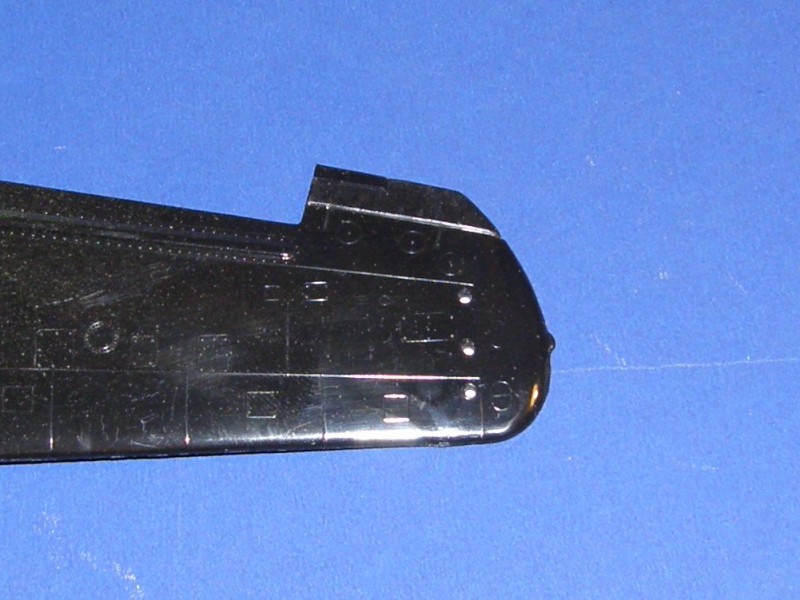
Then stretch some clear sprue and glue it solidly into position
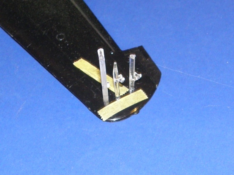
Once the glue sets solidly, trim sand, polish, check, sand, polish, etc, etc
They'll get some silver splashed about the inside of the wing. The tape protects some nearby detail from the forthcoming sanding.
Meanwhile back at Northrop North, I've been working on the IFF lights. Monogram provides 3 circles you're supposed to paint green, yellow and red. That's just not satisfactory, so first drill them out

Then stretch some clear sprue and glue it solidly into position

Once the glue sets solidly, trim sand, polish, check, sand, polish, etc, etc
They'll get some silver splashed about the inside of the wing. The tape protects some nearby detail from the forthcoming sanding.
Posted: Tuesday, November 19, 2013 - 07:00 AM UTC
Hey, something I tried on a model years ago. Is the nose wheel in two halves? There may be a product about called plumbers lead putty. Don't know how dangerous it really is, but its a heavy putty that you can form into the inside of the nose wheel halves and weigh down the front without putting too much stress on the gear strut.

Jessie_C


Joined: September 03, 2009
KitMaker: 6,965 posts
AeroScale: 6,247 posts

Posted: Tuesday, November 19, 2013 - 07:12 AM UTC
That sort of works in the Monogram kit because it's moulded solid, but the Great Wall kit has nice lots of open air between the spokes.
I wonder about casting the entire nose wheel in lead? At any rate, the wheel isn't large enough to contain enough lead to weigh the nose down. I had to get pretty creative about weight in the last one of these I did. The Terry Dean weights fit in front of the instrument panel and under the gunner's seat, or if you're not going to install the radar, they fill the nose cone.
I wonder about casting the entire nose wheel in lead? At any rate, the wheel isn't large enough to contain enough lead to weigh the nose down. I had to get pretty creative about weight in the last one of these I did. The Terry Dean weights fit in front of the instrument panel and under the gunner's seat, or if you're not going to install the radar, they fill the nose cone.
Tailor

Joined: May 26, 2008
KitMaker: 1,168 posts
AeroScale: 199 posts

Posted: Tuesday, November 19, 2013 - 07:28 AM UTC
Joel-
I fully recommend Jean-Luc's article and I think if you contact him he might give you an idea.
https://aeroscale.kitmaker.net/features/4273&page=3
Please let us know what you find out!
Guido
I fully recommend Jean-Luc's article and I think if you contact him he might give you an idea.
https://aeroscale.kitmaker.net/features/4273&page=3
Please let us know what you find out!
Guido
Joel_W

Joined: December 04, 2010
KitMaker: 11,666 posts
AeroScale: 7,410 posts

Posted: Tuesday, November 19, 2013 - 07:49 AM UTC
Jessica, I just sent Terry an email on how I go about purchasing two weights for the P-61A. One is for you. Consider it payback for the turret. Will keep you informed. Will need your address to ship it to you when I get them.
Guido, thanks. I'll explore that route as well.
Joel
Guido, thanks. I'll explore that route as well.
Joel

Jessie_C


Joined: September 03, 2009
KitMaker: 6,965 posts
AeroScale: 6,247 posts

Posted: Tuesday, November 19, 2013 - 09:02 AM UTC
Thank you, but I'm going to need both the Monogram and the GWH weights, which will put the cost up.
When Monogram first tooled this kit in 1974 the level of detail was fantastic. But in keeping with the limitations of mould cutting at the time, some if it is in bas-relief, and could benefit with replacement. This is especially evident with the various throttles, levers and oxygen hoses so a little trimming and replacing later
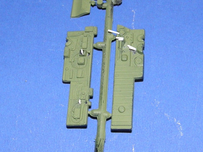
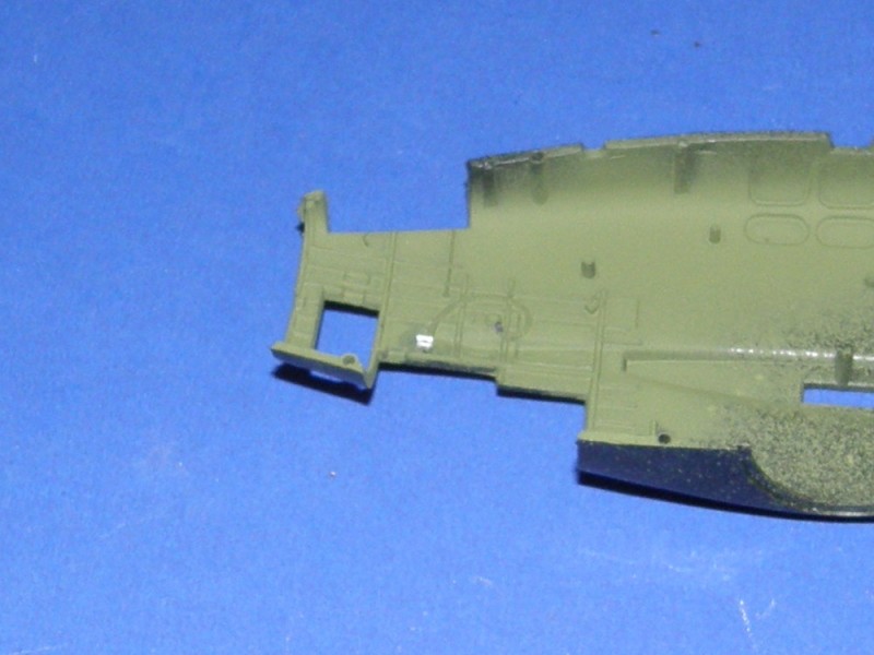
I've mislaid my supply of dead guitar strings so I had to come up with a replacement. First, take a loop of beading wire and secure it in the vice grips
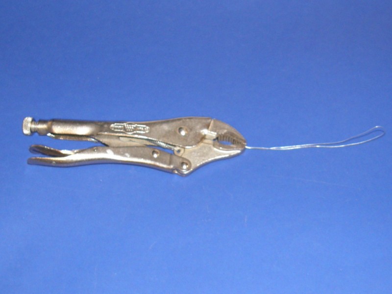
Come on baby, do the twist
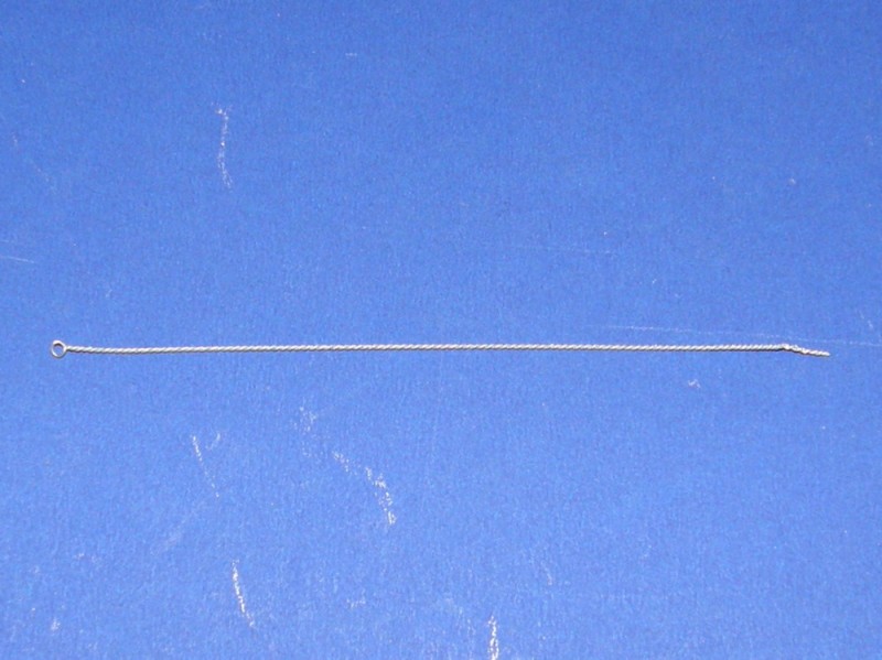
A little olive drab paint, et voilą!

NO, NO, NO! That's not what I want! Now where was I before I was so rudely interrupted? Oh, yes. Et voilą!
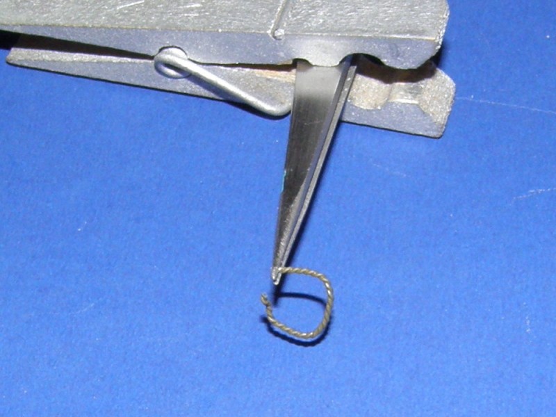
One ready-made oxygen hose!
When Monogram first tooled this kit in 1974 the level of detail was fantastic. But in keeping with the limitations of mould cutting at the time, some if it is in bas-relief, and could benefit with replacement. This is especially evident with the various throttles, levers and oxygen hoses so a little trimming and replacing later


I've mislaid my supply of dead guitar strings so I had to come up with a replacement. First, take a loop of beading wire and secure it in the vice grips

Come on baby, do the twist

A little olive drab paint, et voilą!

NO, NO, NO! That's not what I want! Now where was I before I was so rudely interrupted? Oh, yes. Et voilą!

One ready-made oxygen hose!
Joel_W

Joined: December 04, 2010
KitMaker: 11,666 posts
AeroScale: 7,410 posts

Posted: Tuesday, November 19, 2013 - 09:12 AM UTC
Quoted Text
Thank you, but I'm going to need both the Monogram and the GWH weights, which will put the cost up.
Jessica, I see. I'll pm you when I hear from Terry.
Joel
Joel_W

Joined: December 04, 2010
KitMaker: 11,666 posts
AeroScale: 7,410 posts

Posted: Tuesday, November 19, 2013 - 09:31 AM UTC
Continuing with my plan to start construction with the engine/engine booms, I started to detail the main wheel wells. I've only worked on one engine boom at this point, but the detail work should go much faster on the 2nd one.
Here's the top of the main wheel well with ribbing and the rear bulkhead added.
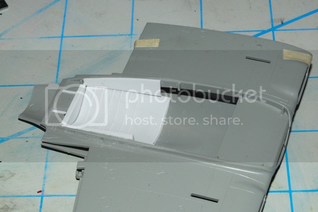
Here is the Wheel well with the landing gear sub assembly installed. I've also added some wiring and boxes to make it more visually interesting.
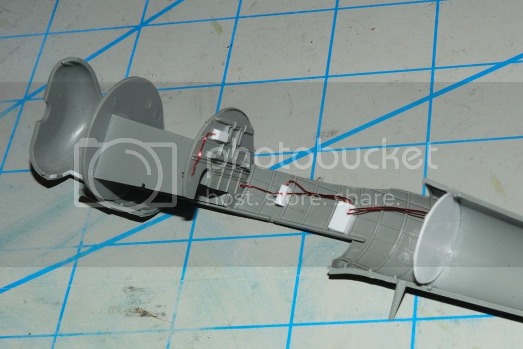
The interior of the boom looking down from where the wing mates to the boom.
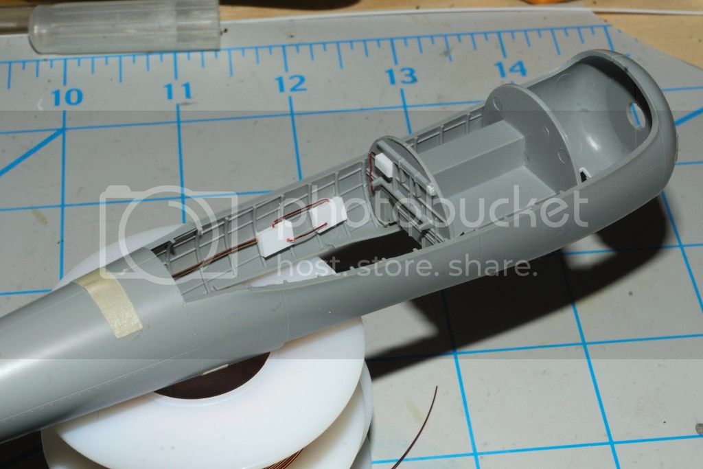
And lastly, two pictures of the completed well ready for priming, then a coat of Yellow Zinc Chromate.
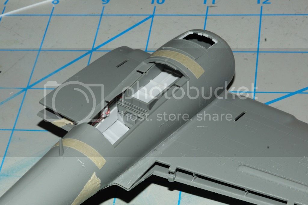

Right behind the cut out for the screening, there is a closed exhaust. I thought about cutting it open and making a new exhaust cover, but the wheel well bulkhead is right behind it. Next option is to trim it back, so that a sense of depth is achieved, then using sheet plastics build a new one right on top of the molded one. Think I'll go with that concept.
Joel
Here's the top of the main wheel well with ribbing and the rear bulkhead added.
Here is the Wheel well with the landing gear sub assembly installed. I've also added some wiring and boxes to make it more visually interesting.
The interior of the boom looking down from where the wing mates to the boom.
And lastly, two pictures of the completed well ready for priming, then a coat of Yellow Zinc Chromate.
Right behind the cut out for the screening, there is a closed exhaust. I thought about cutting it open and making a new exhaust cover, but the wheel well bulkhead is right behind it. Next option is to trim it back, so that a sense of depth is achieved, then using sheet plastics build a new one right on top of the molded one. Think I'll go with that concept.
Joel

Jessie_C


Joined: September 03, 2009
KitMaker: 6,965 posts
AeroScale: 6,247 posts

Posted: Tuesday, November 19, 2013 - 09:40 AM UTC
Quoted Text
Right behind the cut out for the screening, there is a closed exhaust. I thought about cutting it open and making a new exhaust cover, but the wheel well bulkhead is right behind it. Next option is to trim it back, so that a sense of depth is achieved, then using sheet plastics build a new one right on top of the molded one. Think I'll go with that concept.
Be careful about that! According to Jean-Luc's article that's an access door, not a vent, and should be sanded flush. It's wrong on the Monogram kit, too.
Joel_W

Joined: December 04, 2010
KitMaker: 11,666 posts
AeroScale: 7,410 posts

Posted: Tuesday, November 19, 2013 - 11:08 AM UTC
Jessica, thanks for the heads up. The 1/32 scale Hobby Boss kit also has that access or exhaust opening. Strange that everyone has gotten it wrong.
I've looked at dozens and dozens of pictures, but none really shows that area on the engine boom. Been to the Reading restoration site, and can't find any pictures of it either. Going to try and contact them for a definitive explanation of what it exactly is.
Joel
I've looked at dozens and dozens of pictures, but none really shows that area on the engine boom. Been to the Reading restoration site, and can't find any pictures of it either. Going to try and contact them for a definitive explanation of what it exactly is.
Joel

Jessie_C


Joined: September 03, 2009
KitMaker: 6,965 posts
AeroScale: 6,247 posts

Posted: Tuesday, November 19, 2013 - 01:18 PM UTC
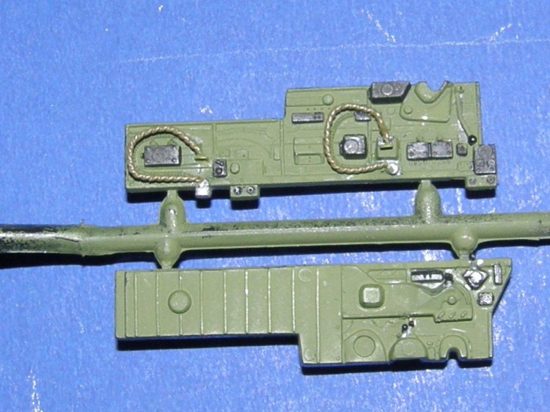
Now the sticky-out thingys in the cockpit have a coat of paint and they're much more invisible

Joel_W

Joined: December 04, 2010
KitMaker: 11,666 posts
AeroScale: 7,410 posts

Posted: Tuesday, November 19, 2013 - 01:37 PM UTC
Jess, your cockpit is starting to look good. Those "sticky out thingy's" are flexible oxygen tubes.While I believe that they were painted in interior green, but they photographed as a lighter shade of IG.
Joel
Joel
Removed by original poster on 11/20/13 - 01:37:32 (GMT).

Jessie_C


Joined: September 03, 2009
KitMaker: 6,965 posts
AeroScale: 6,247 posts

Posted: Tuesday, November 19, 2013 - 01:39 PM UTC
And the other sticky-out thingys are the throttles, levers and other various knobby bits that I put in there so well that they're invisible 

Joel_W

Joined: December 04, 2010
KitMaker: 11,666 posts
AeroScale: 7,410 posts

Posted: Tuesday, November 19, 2013 - 01:44 PM UTC
Jessica, bottom line is that it's looking really good.
Joel
Joel
Tailor

Joined: May 26, 2008
KitMaker: 1,168 posts
AeroScale: 199 posts

Posted: Tuesday, November 19, 2013 - 05:48 PM UTC
There are indeed only a few pics of the underside of the boom. I think that the makers used all the same source plans, that why they all get into trouble in this particular part of the plane. I remember seeing 2 oir 3 quite half-conclusive pictures of this area, but I guess the Utracast detail set has it about right


Jessie_C


Joined: September 03, 2009
KitMaker: 6,965 posts
AeroScale: 6,247 posts

Posted: Tuesday, November 19, 2013 - 06:04 PM UTC
What about the panel immediately behind the grille? It looks as though it's a partially open vent, but Jean-luc says it's an access door which should be flush with the boom surface.
Tailor

Joined: May 26, 2008
KitMaker: 1,168 posts
AeroScale: 199 posts

Posted: Tuesday, November 19, 2013 - 07:30 PM UTC
It looks to me as though the vent shape has been sanded down to "almost" flush with the surroundings. I could be wrong though.
Joel_W

Joined: December 04, 2010
KitMaker: 11,666 posts
AeroScale: 7,410 posts

Posted: Wednesday, November 20, 2013 - 03:59 AM UTC
Guido, what Jessica and I were talking about is the access panel/exhaust, or whatever it is, which is located right behind the screening. In your pictures it looks like it's in the closed position. I've seen pictures of the PE set for the Hobby Boss 1/32 kit where it's in the open mode.
I've looked at dozens and dozens of pictures of the real aircraft, and this isn't an area where any known photos (to me) exist. I did find one picture, but the area in question is in deep shadows, so you can't see a thing.
Using the Edward PE set as a guide, the top is a two pc affair, that is hinged from the sides. This could also be an access door, but to what?
Right now, I'm going with a compromise to the situation. I'm sanding down the molded section, then scribing a recessed panel. Then adding a .010 plastic sheet to represent a closed door, or a closed vent.
Joel
I've looked at dozens and dozens of pictures of the real aircraft, and this isn't an area where any known photos (to me) exist. I did find one picture, but the area in question is in deep shadows, so you can't see a thing.
Using the Edward PE set as a guide, the top is a two pc affair, that is hinged from the sides. This could also be an access door, but to what?
Right now, I'm going with a compromise to the situation. I'm sanding down the molded section, then scribing a recessed panel. Then adding a .010 plastic sheet to represent a closed door, or a closed vent.

Joel
Joel_W

Joined: December 04, 2010
KitMaker: 11,666 posts
AeroScale: 7,410 posts

Posted: Wednesday, November 20, 2013 - 04:57 AM UTC
Joel_W

Joined: December 04, 2010
KitMaker: 11,666 posts
AeroScale: 7,410 posts

Posted: Tuesday, November 26, 2013 - 10:46 AM UTC
After our discussion on exactly what the area directly behind the intake screen is, photographic proof showed that it wasn't the exhaust that virtually every kit manufacture has depicted, but rather a cover plate or access hatch. So I filed/sanded the exhaust off, then made a cover plate from .040 sheet.
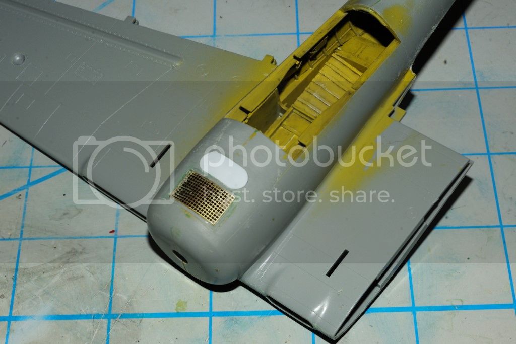
I also glued on the oil cooler grill over the cut out opening, rather then directly to the plastic backing. I was trying to produce a more realistic look to the screening, which I think the cut out achieved.
Joel
I also glued on the oil cooler grill over the cut out opening, rather then directly to the plastic backing. I was trying to produce a more realistic look to the screening, which I think the cut out achieved.
Joel

Jessie_C


Joined: September 03, 2009
KitMaker: 6,965 posts
AeroScale: 6,247 posts

Posted: Tuesday, November 26, 2013 - 11:23 AM UTC
That looks right spiffy!
Joel_W

Joined: December 04, 2010
KitMaker: 11,666 posts
AeroScale: 7,410 posts

Posted: Tuesday, November 26, 2013 - 11:44 AM UTC
Jessica, Thanks so much for the kinds words. Haven't heard the word spiffy used for some time. Glad it's making a come back.
Joel
Joel
 |


