World War II
Discuss WWII and the era directly before and after the war from 1935-1949.
Hosted by Rowan Baylis
1/48 B-17F Build - 303rd BGs Luscious Lady
Joel_W
Staff MemberAssociate Editor
AUTOMODELER
_VISITCOMMUNITY
New York, United States
Joined: December 04, 2010
KitMaker: 11,666 posts
AeroScale: 7,410 posts
Posted: Thursday, July 11, 2019 - 02:35 AM UTC

Quoted Text


Quoted Text

Brian,
I honestly look forward to your posts, but the ones that I'm really dying most of all is anything that relates to HG. I still can quite understand how he can do scribing to that level, which is absolutely 100% perfect, then do it all over again on the other wing.
Joel


Careful now, you don't want to give him a swelled head! I think his "magic" is simply the result of experience and very hard concentration while doing particular tasks. Plus very strong native talent.

Estimated completion time for the whole build, I'm told, is about six months.


Brian,
Only six months to finish the build. Sure seems like that is pushing it some.

Joel
Redhand
#522
_VISITCOMMUNITY
New Jersey, United States
Joined: January 20, 2013
KitMaker: 1,460 posts
AeroScale: 1,443 posts
Posted: Thursday, July 11, 2019 - 09:49 AM UTC

Quoted Text


Quoted Text


Quoted Text

Brian,
I honestly look forward to your posts, but the ones that I'm really dying most of all is anything that relates to HG. I still can quite understand how he can do scribing to that level, which is absolutely 100% perfect, then do it all over again on the other wing.
Joel


Careful now, you don't want to give him a swelled head! I think his "magic" is simply the result of experience and very hard concentration while doing particular tasks. Plus very strong native talent.

Estimated completion time for the whole build, I'm told, is about six months.


Brian,
Only six months to finish the build. Sure seems like that is pushing it some.

Joel


He won't rush it. However long it takes but that's his best estimate at this point.
Joel_W
Staff MemberAssociate Editor
AUTOMODELER
_VISITCOMMUNITY
New York, United States
Joined: December 04, 2010
KitMaker: 11,666 posts
AeroScale: 7,410 posts
Posted: Friday, July 12, 2019 - 12:32 AM UTC

Quoted Text


Quoted Text


Quoted Text


Quoted Text

Brian,
I honestly look forward to your posts, but the ones that I'm really dying most of all is anything that relates to HG. I still can quite understand how he can do scribing to that level, which is absolutely 100% perfect, then do it all over again on the other wing.
Joel


Careful now, you don't want to give him a swelled head! I think his "magic" is simply the result of experience and very hard concentration while doing particular tasks. Plus very strong native talent.

Estimated completion time for the whole build, I'm told, is about six months.


Brian,
Only six months to finish the build. Sure seems like that is pushing it some.

Joel


He won't rush it. However long it takes but that's his best estimate at this point.


Brain,
Just seems like a ton of work left starting with both wheel wells that he'll detail to the nth degree. But I guess that when you can work at that level consistently, amazing things just happen in short order.

Joel
Redhand
#522
_VISITCOMMUNITY
New Jersey, United States
Joined: January 20, 2013
KitMaker: 1,460 posts
AeroScale: 1,443 posts
Posted: Monday, July 15, 2019 - 03:46 PM UTC
MORE ENGINE WORK

There has been real progress in the last few days.

But first, a bit of a disappointment. The braided brass and dark metal ignition wires from Germany proved too big for 1/48.


Had they been the right size, we would have had engines that look like this:


This is a 1/24 engine.

The vendor is brand new (2019) ANZI Models, https://anyz.io/

However, what we have still looks "pretty good" in H.G.'s hands.


Each engine is going to look a bit different, based on the photographic evidence we have.

He's an incomplete "bare aluminum" one with brass ignition wires. You get the picture:


H.G. did another bare metal one, but with weathered aluminum ignition wires.


Nice to see the contrast with two mounted!


Finally, he's going to do another "dark" one, but with two-toned cylinder barrels and heads like this refurbished one that went into the restored "Memphis Belle":


Right now it's a work in progress


but this will give you some idea of how these "bad boys" will look four abreast:


I can almost hear the starter motors!

BTW, each prop will be different as well, based on photos of the real items in 303rd photos.

GazzaS
#424
_VISITCOMMUNITY
Queensland, Australia
Joined: April 23, 2015
KitMaker: 4,648 posts
AeroScale: 1,938 posts
Posted: Monday, July 15, 2019 - 09:50 PM UTC
Those engines look awesome! Really glad to see this one steaming ahead.

Gaz
Joel_W
Staff MemberAssociate Editor
AUTOMODELER
_VISITCOMMUNITY
New York, United States
Joined: December 04, 2010
KitMaker: 11,666 posts
AeroScale: 7,410 posts
Posted: Tuesday, July 16, 2019 - 01:06 AM UTC
Brian,
HG's work on the ignition wiring is way more then just 1st class, it's in a class of itself.

One thing that I was always guilty of, as most modelers in the smaller scales were of not properly wiring the cylinders. By that I mean that one ignition wire was run along and clamped to a push rod sleeve, then makes the left hand turn to the plug, while the other ignition wire more or less went straight up the middle of the heads. Mine were shall we say somewhat creative with the goal of just getting the plugs wired. Often no two cylinders looked similar, and the resulting wiring was more of a freelance exercise.

Now HG's are all almost identical, which has a far greater realistic look to each miniature engine.

Joel


Redhand
#522
_VISITCOMMUNITY
New Jersey, United States
Joined: January 20, 2013
KitMaker: 1,460 posts
AeroScale: 1,443 posts
Posted: Wednesday, July 17, 2019 - 02:52 PM UTC
UPPER WINGS - THE SHAPE OF THINGS TO COME

I'm pretty awestruck by H.G.'s scribing start on the upper wings. Check this out.


Not to worry about the scribing over the fuel cap cover locations. This is early in the game.


And look at this nacelle.


As always, I'm impressed by H.G.'s eye for detail. He asked me about nacelle hose opening locations like this.


It looks like an overflow vent for the engine oil tank, which I believe is just visible inside the access hatch.

Karl, where would I find info on these locations? In the B-17F Erection and Maintenance Manual?
KPHB17FE
_VISITCOMMUNITY
Illinois, United States
Joined: January 12, 2015
KitMaker: 292 posts
AeroScale: 292 posts
Posted: Wednesday, July 17, 2019 - 10:17 PM UTC
It's the oil tank drain. Been there, done that:

Joel_W
Staff MemberAssociate Editor
AUTOMODELER
_VISITCOMMUNITY
New York, United States
Joined: December 04, 2010
KitMaker: 11,666 posts
AeroScale: 7,410 posts
Posted: Thursday, July 18, 2019 - 12:36 AM UTC
Brian,
After looking at HG's latest scribing, it's become quite apparent that he's most certainly an Alien. Honestly, I've never seen computer generated recessed lines on any kit compare to what he's accomplished. Both the scribing and the riveting combined is 100% definitely from another planet. There just isn't any other explanation.

Joel
Redhand
#522
_VISITCOMMUNITY
New Jersey, United States
Joined: January 20, 2013
KitMaker: 1,460 posts
AeroScale: 1,443 posts
Posted: Thursday, July 18, 2019 - 11:54 AM UTC
MORE WING WORK, AND ... FUEL FILLER CAPS!


Quoted Text

Not to worry about the scribing over the fuel cap cover locations.


H.G. and I had a discussion about the work-time cost-benefit of putting the Eduard Brass fuel filler caps I sent him (Sadly, that item is OOP now) slightly elevated above the wing surface or countersunk flush, "like the real thing."


My view was that it was simply too difficult to countersink them and I didn't want to be unreasonable in my requests. H.G. affected that it was no big deal, so I left it at that.

Check this out.


I could not have pulled this off in a million years.


I am fresh out of superlatives. They are flush.


There is some finishing work to do on the wing (of course) but I'm not complaining.


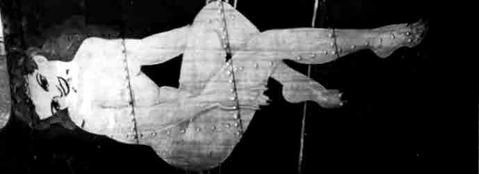
This plant picture is interesting because it shows the wings on the real thing scuffed up during construction just like on the model.


Pay no attention to the pretty factory worker in the foreground!
Joel_W
Staff MemberAssociate Editor
AUTOMODELER
_VISITCOMMUNITY
New York, United States
Joined: December 04, 2010
KitMaker: 11,666 posts
AeroScale: 7,410 posts
Posted: Friday, July 19, 2019 - 01:18 AM UTC
Brian,
As I continually state, HG has to be an Alien. There just isn't any other explanation.

Joel
KPHB17FE
_VISITCOMMUNITY
Illinois, United States
Joined: January 12, 2015
KitMaker: 292 posts
AeroScale: 292 posts
Posted: Friday, July 19, 2019 - 02:24 AM UTC
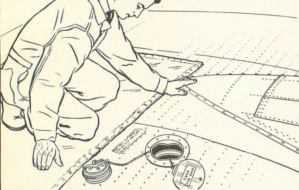
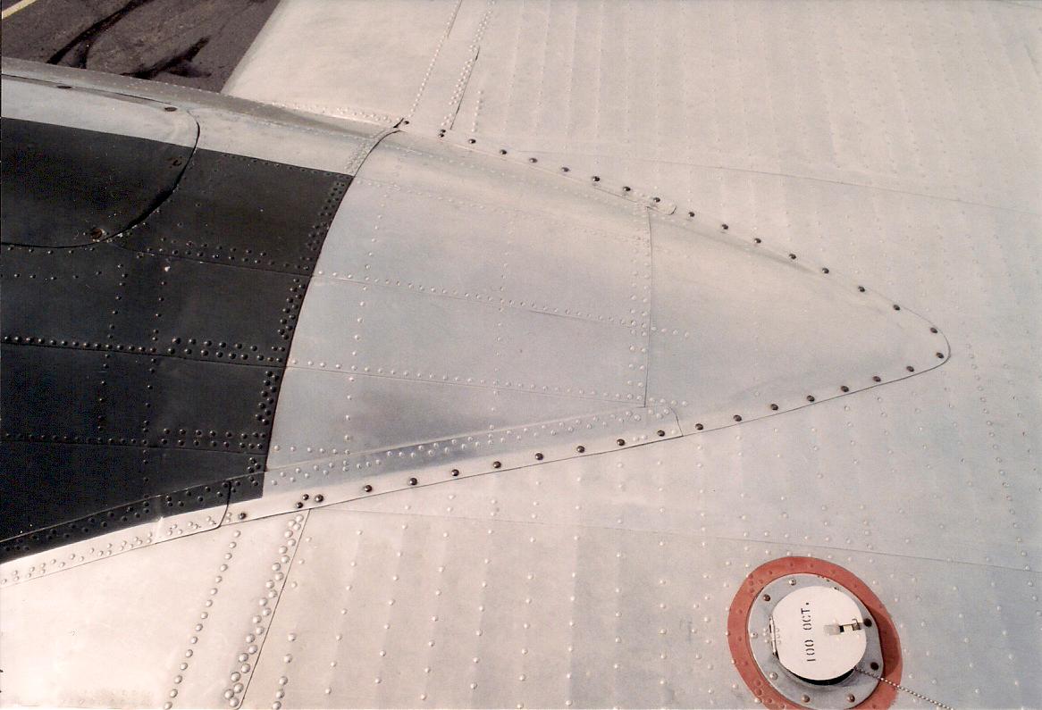
Um, I hate to be a party pooper but the fuel caps are recessed several inches below the wing surface. All that is seen from the outside is a cover:


KPHB17FE
_VISITCOMMUNITY
Illinois, United States
Joined: January 12, 2015
KitMaker: 292 posts
AeroScale: 292 posts
Posted: Friday, July 19, 2019 - 02:33 AM UTC
Another little gripe of mine: NO ONE puts out the correct decals and stencils for the fuel cells of the B-17. I wish I could print these, I have drawn them up in a CAD format if anyone can reproduce them (this is only the part of the sheet that applies to F models):


Here is the complete sheet with notes and other details:

Redhand
#522
_VISITCOMMUNITY
New Jersey, United States
Joined: January 20, 2013
KitMaker: 1,460 posts
AeroScale: 1,443 posts
Posted: Friday, July 19, 2019 - 03:01 AM UTC

Quoted Text

Um, I hate to be a party pooper but the fuel caps are recessed several inches below the wing surface. All that is seen from the outside is a cover:


No problem! We welcome your comments and info always, Karl! If you want to email that CAD sheet to me we can definitely print up some extra decal sets for you!!

I'm emailing H.G. now telling him to look at the blog.

Brian
Redhand
#522
_VISITCOMMUNITY
New Jersey, United States
Joined: January 20, 2013
KitMaker: 1,460 posts
AeroScale: 1,443 posts
Posted: Friday, July 19, 2019 - 05:36 AM UTC

Quoted Text

Brian,
As I continually state, HG has to be an Alien. There just isn't any other explanation.

Joel


Now you know why I called myself an "advanced journeyman" at the beginning of this blog. I think of H.G. an artisan in the Florentine sense.


This work crosses the line into pure artistry.
Redhand
#522
_VISITCOMMUNITY
New Jersey, United States
Joined: January 20, 2013
KitMaker: 1,460 posts
AeroScale: 1,443 posts
Posted: Sunday, July 21, 2019 - 07:26 AM UTC
WORK IN PROGRESS. LANDING GEAR!

I have never been particularly happy with the "look" of the Revell/Monogram B-17 landing gear parts. They have always appeared somewhat "off" to me, a 1980s kit manufacturer's compromise because nobody is going to be looking too closely at the wheel wells, are they?

In any event, I didn't mention this specifically to HG, but did ask him how he was thinking of integrating the landing gear into the planned detailing of the wheel wells.

Little did I expect what you are about this see here: an almost complete rebuild.

I will let the pictures speak for themselves, as I'm still not sure what final form this effort will take, other than to say that this work is another example of modeling taken to the next level.

The below picture shows the details of what HG is trying to replicate.


And here we go. You will see that HG is rejecting the white metal landing gear parts in favor of his own creation using the resin parts from the Verlinden set, together with home cut metal.


This last photo suggests to me that he may be doing away completely with the intermediate kit plastic plate with the hole for the wheel and tire.


What impresses me is both the physical workmanship of the handmade and modified parts as well as the "engineering" behind the modified design.

Joel_W
Staff MemberAssociate Editor
AUTOMODELER
_VISITCOMMUNITY
New York, United States
Joined: December 04, 2010
KitMaker: 11,666 posts
AeroScale: 7,410 posts
Posted: Sunday, July 21, 2019 - 07:41 AM UTC
Brian,
Even for an Alien, this is simply amazing stuff.

Joel
Redhand
#522
_VISITCOMMUNITY
New Jersey, United States
Joined: January 20, 2013
KitMaker: 1,460 posts
AeroScale: 1,443 posts
Posted: Friday, July 26, 2019 - 12:28 PM UTC
MORE LANDING GEAR AND WHEEL WELL PREP WORK

H.G. is grinding it out, doing work to position the landing gear in the nacelles, and getting both the gear and the wells set up for later detailing.

So far as I am concerned, this is the most technically challenging part of the build, given the detail and the kit part configuration. Not to mention that the landing gear must be firmly fixed in the nacelles because they hold the whole model up!

It's clear the designers of the kit engineered it with no regard for the wheel well details, but rather as a platform to hold and position the kit landing gears, which are cut off at the insertion points where the ends fit into the flat kit parts. The only concession to "realism" is the oval openings in the parts to "make space" for the tires themselves, because even with a passing glance inside the nacelles it would look flawed and strange for there to be no space for the wheels to "fit" when "retracted."

I'm not really criticizing this kit design decision. It was the "state of the art" and detail at the time, and besides, "Who's going to really pick up the model and look inside the wheel wells?" From a functional display standpoint, the wheel wells were "invisible."

As a refresher, let's look at the kit parts again to see what I'm trying to describe.


Now let's look at a real wheel well. The below pictures come from the site at the link.


It's fair to say these show just how wide open the wheel well is, and how much detail is missing from the kit configuration. I particularly like the last one, showing what I think is the black hydraulic pump and gearbox that drives the ball screw actuator, which in turn raises and lowers the landing gear.

My understanding is that H.G. is going to use the flat kit parts as a locator for the landing gear,


but that he is then going to cut away most of it so that the whole well is visible.

Here's some of the prep work:


The supercharger location detail in the above picture is to highlight an additional mod H.G. is going to make: widening the channel forward to replicate the "Y" shaped exhaust piping at the front underneath the cowl flaps. See below.


Finally, a teaser. To ensure a level fit, H.G. is hand-manufacturing a jig on which to place the taped-together model with gear installed


In the world of real aerospace component manufacturing, which I lived in during the first 20 years of my legal career at Curtiss-Wright, such things are called "tooling" and "fixtures." They are essential components of the manufacturing process.

The below picture, "Huge drop hammers day and night forming sheet metal parts for B-25s and P-51s built at the North American Aviation Inc. plant in Inglewood in October 1942. Alfred T. Palmer / U.S. Office of War Information." illustrates "tooling" if yuz asks me.


This one, from a picture captioned, "Mounting motor on a B-25 bomber at North American Aviation Inc. plant in Inglewood in 1942. Alfred T. Palmer / U.S. Office of War Information," at the same site shows a "fixture" IMHO. I refer to the "L" shaped brown piping used to hold the front of the engine up during installation on the aircraft.


As I have said before, all this is waaaaaay above my labor grade.

QUESTION FOR KARL: What color were the wheel well interiors painted, or were they left bare metal at the factory or sprayed with some kind of clear primer? Also, did we make any mistakes technically?

Karl, I also have some questions about exterior detailing on the supercharger piping leading from the cowling. Is there an exterior difference in the parts based on the fact that the F model had hydraulic controls for the superchargers, but the G model had an improved electronic control system. The guy who makes the "Resin2Detail" parts has a pair of outer nacelle pipes that I think were intended just for the G model.
http://resin2detail.com/product/ac48005/


I don't know. I do have a set of these. Thanks.
Joel_W
Staff MemberAssociate Editor
AUTOMODELER
_VISITCOMMUNITY
New York, United States
Joined: December 04, 2010
KitMaker: 11,666 posts
AeroScale: 7,410 posts
Posted: Saturday, July 27, 2019 - 01:18 AM UTC
Brian,
Even I have run out of words & expressions to describe HG's incredible corrections and detailing. I'm just in awe of the work he's done so far on the wheel wells and the gear.

Joel
HGBARNES
Staff MemberAssociate Editor
AEROSCALE
_VISITCOMMUNITY
Alberta, Canada
Joined: March 15, 2017
KitMaker: 45 posts
AeroScale: 33 posts
Posted: Saturday, July 27, 2019 - 05:18 PM UTC
Make no mistake, Brian is the mind behind this... read his book! It's a pleasure to help.
Redhand
#522
_VISITCOMMUNITY
New Jersey, United States
Joined: January 20, 2013
KitMaker: 1,460 posts
AeroScale: 1,443 posts
Posted: Sunday, July 28, 2019 - 01:03 AM UTC

Quoted Text

Make no mistake, Brian is the mind behind this... read his book! It's a pleasure to help.


HG: Let me say publicly what I have privately. The biggest compliment I've ever been paid as a modeler is that you decided to complete this project to "do justice" to my prior work on it.
KPHB17FE
_VISITCOMMUNITY
Illinois, United States
Joined: January 12, 2015
KitMaker: 292 posts
AeroScale: 292 posts
Posted: Sunday, July 28, 2019 - 06:37 AM UTC
The exhaust on the left IB engine has boilers and lines related to the heating system. Nothing to do with the turbos. These were not on the #3 exhaust (except for a very few but we won't get into that!) so it was just a plain pipe. Monogram, and thus Revell, got a lot of details right. This was one of them.

Here is the #2 exhaust on the Belle with the boilers and related lines (They actually have only two boilers installed and a cover plate over the other but you get the idea:


Here in the glycol system in the #2 nacelle. The boilers in the exhaust heated the glycol and then the hot glycol was routed to a heat exchanger in the wing root:


Here is the entire system. Air was run through the heat exchanger and warmed up then routed in various places in the fuselage. How effective was it? Not very according to most but I have met a couple of pilots who said they were comfortable in the cockpit. Still warmly dressed but not wearing the shearling gear and so they could operate fairly well.


Redhand
#522
_VISITCOMMUNITY
New Jersey, United States
Joined: January 20, 2013
KitMaker: 1,460 posts
AeroScale: 1,443 posts
Posted: Sunday, July 28, 2019 - 09:26 AM UTC
Fascinating! Many thanks, Karl. I'll let HG know. I'm learning things I never knew about the A/C. I always wondered what those details on that pipe were. And, you are correct to call the pipe part of the exhaust system rather than the turbo system.

Any thoughts about the original interior colors of the wheel wells? My money is on aluminum with no paint, but what do I know?

Thanks again.


KPHB17FE
_VISITCOMMUNITY
Illinois, United States
Joined: January 12, 2015
KitMaker: 292 posts
AeroScale: 292 posts
Posted: Sunday, July 28, 2019 - 10:21 AM UTC
I have some photos of the unrestored wheel wells of the "Memphis Belle" but they are not mine to share. What I do have is the post restoration photos that I took and I can tell you that they followed the originals. The aft bulkhead was painted and the straps holding the oil tank. Everything else is unpainted.

View aft in #2 nacelle:


View forward in #2 nacelle. Panel has been removed from the firewall for engine access:


View to the left of the #2 nacelle. Those white wrapped lines are for the glycol system we were just discussing:


Looking up and to the right. Glycol tank is at the top, the oil tank is to the left.


Just cuz it interests me, the glycol tank:


Little dark, forward, up and right. The object angling down is the gear retract strut. At the top of it, you can see the black retract motor. The rod running to it is for the manual retract system.


Redhand
#522
_VISITCOMMUNITY
New Jersey, United States
Joined: January 20, 2013
KitMaker: 1,460 posts
AeroScale: 1,443 posts
Posted: Sunday, July 28, 2019 - 01:18 PM UTC
Wonderful pictures. Thanks.

I was surprised that the heating system was glycol, but there is some sense to exhaust heated "antifreeze" being a heating agent in freezing air, isn't there?