World War II
Discuss WWII and the era directly before and after the war from 1935-1949.
Hosted by Rowan Baylis
1/48 B-17F Build - 303rd BGs Luscious Lady
Redhand
#522
_VISITCOMMUNITY
New Jersey, United States
Joined: January 20, 2013
KitMaker: 1,460 posts
AeroScale: 1,443 posts
Posted: Sunday, May 11, 2014 - 07:56 AM UTC
Thanks guys, the feedback is really appreciated. Before doing any build pics, I will show some of the details that I am trying to replicate in the cockpit.

First, a note on the positioning of control columns in the last picture. It is wrong! That's what caused the going backwards episode I will recount.

First, why is it wrong? Answer: the columns are perpendicular. This caused me no end of trouble to correct, as I will recount later.

I think that in the in-flight surface neutral position the control columns actually cant forward a fair amount. Check out these pics:


And here is a view of the modernized cockpit in The Collins Foundation's 909:


You will see what trouble this got me into in the next post.
Dragon164
#226
_VISITCOMMUNITY
British Columbia, Canada
Joined: February 20, 2012
KitMaker: 1,909 posts
AeroScale: 508 posts
Posted: Sunday, May 11, 2014 - 12:08 PM UTC
Brian,
Don't forget that with the columns forward the elevators will be down.

Cheers Rob.
Redhand
#522
_VISITCOMMUNITY
New Jersey, United States
Joined: January 20, 2013
KitMaker: 1,460 posts
AeroScale: 1,443 posts
Posted: Sunday, May 11, 2014 - 12:39 PM UTC
Here you can see one of my early efforts to attach the lower cockpit floor to the upper floor, throttle pedestal and instrument panel, with white styrene filler to make for an even floor surface. You can clearly see the sides of the "basement doors" from the TD cockpit set and the plan was to fit the Monogram basement doors in between.


I actually got that far, only to run into a clearance problem evident in 1/1 as well as 1/48 scale. It can clearly be seen in the below photo where the 1/1 inner legs attach to the outer coaming of the "basement door."


Simply stated, there was no way the inner and outer seat legs of the Monogram kit were going to fit against the inner TD set coaming and still leave room for the grey dynamotor under the seat. Nor, frankly, was there any way it would easily align with the middle of the control column on each side.

BTW, the above shot shows that the lower B-17 floor is not only plywood, but heavily used and discolored plywood into the bargain.

I addressed this problem by: (1) ripping off the TD set coamings and (2) gluing a solid sheet styrene square over the hole, then (3) painting it like the rest of the floor, and (4) raising up the garage door sides because the tunnel hole was larger in height than the Monogram basement doors.

I then sanded the sides of the dynamotors and glued then to the sides of the basement door coamings. (I had long since sanded off the floor bases for the dynamotors because they weren't positioned correctly for the Monogram seats.)

The result was the seats you see glued to the bottom floor below.


But I was unhappy with how it looked, for reasons discussed in the next post, and then embarked on a cure that almost proved worse than the disease.
Removed by original poster on 05/12/14 - 02:55:14 (GMT).
Redhand
#522
_VISITCOMMUNITY
New Jersey, United States
Joined: January 20, 2013
KitMaker: 1,460 posts
AeroScale: 1,443 posts
Posted: Sunday, May 11, 2014 - 02:57 PM UTC

Quoted Text

Are the instruments individual decals, or did you actually paint them?

Joel


The B-17 instrument panel is Eduard colored photo-etched brass, two pieces one on top of the other, and bent around the right corner. Can't beat it, though I have used a Waldron punch-set and Mike Grant instrument decals to good effect in a B-29 build of a few years ago. See below.


Redhand
#522
_VISITCOMMUNITY
New Jersey, United States
Joined: January 20, 2013
KitMaker: 1,460 posts
AeroScale: 1,443 posts
Posted: Wednesday, May 14, 2014 - 01:03 PM UTC
Sorry for the B-29 digression. I am getting back to the cockpit in the B-17 Luscious Lady.

The "crisis" I experienced dealt with the pilot seats. When I relocated the control columns with a slight forward cant, I managed to break off both seats, which were somewhat precariously glued to the inner edges of the "basement doors" and the floor. The problem was that the seats were secured mainly by weak butt joins, and there comes a point when successive re-gluings just gets glue all over the place with no strengthening effect, plus brush repainting with the Humbrol bronze green wasn't very elegant, shall we say.

As I manhandled the damn things, some of the seat belts came off, and then a buckle or two from the individual belt pieces. Since the rug in my basement where the work table is could easily pass for bronze green itself, looking for the fallen seatbelts on the floor (little parts ALWAYS fall to the floor in my modeling universe, and frequently migrate to its alternate) had me reflecting on the lyrics of the Genesis song, "You're taking it all too hard":

OH NO NOT THE SAME MISTAKES AGAIN

I wound up ripping the garage doors out, sanding them down to eliminate the accumulated build-up of crazy glue on the edges, and also sanding down the legs below the seats, then respraying bronze green over the whole lot.

Most importantly, I drilled a pin hole in the garage door edges at the top where the front inner chair legs join, and did the same at the bottom of the legs. That created at least one strong attachment point for each seat.

I also more heavily weathered the plywood floor. I don't like overdoing this, but my sense is that the wood floors in these B-17s got VERY heavy use so it was appropriate.

You can see the results of the repair job in the pictures below.


The astute observer will note that the Boeing logos at the center of the control wheels also look slightly different from those in earlier cockpit shots. That's because they are. I lost one of the original brass ones (on the floor) when tilting the control columns forward, then removed the one that was left, and took it to my computer scanner where I scanned a number of images of it, then punched the images out with my Waldron punch set. Not as nice as the brass, but it gets the job done. [On reflection, I could have kept it with just one, since these logos were frequently ripped off as souvenirs, but who knows in this case?]

If not obvious, let me state that the control columns are all pinned, column bases to the floor, and control wheels to the tops of the columns. I got the forward cant to the control columns by sanding the bottoms at an angle, and pinning them to the floor pedestals. Pinning is all but essential IMO when dealing with small resin parts.

Below you will see the left side wall to the pilot's seat, including just detailed and installed yellow oxygen bottles.


I am very happy with how it came out. The irony is that when that sidewall is added to the model and the halves put together, next to none of the detail on the piece can be seen, and also that it greatly obscures the lower seat legs and the floor I weathered.

My OCD side shouldn't have worried about the sloppy brush paint, etc. etc, but we all know how futile that mental exercise is: for an AMS sufferer it MUST look as good as possible even if it can't be seen because you know it's there.

Next time I will talk about how I researched and detailed the oxygen bottles. That was one of the most fun parts of the build to date: Gotta love them metal securing straps!


Redhand
#522
_VISITCOMMUNITY
New Jersey, United States
Joined: January 20, 2013
KitMaker: 1,460 posts
AeroScale: 1,443 posts
Posted: Sunday, May 18, 2014 - 02:14 AM UTC
OXYGEN BOTTLES AND AFTER COCKPIT, STBD. SIDE

In the last post I mentioned I would discuss detailing the oxygen bottles. The way to start the discussion is by looking at the real thing:


This is the cockpit area in a restored B-17 (I forget which).

Better views of the oxygen bottles are available here in B-24 interior shots, the first period, the second restored (I think).


In looking at these I thought it best to replicate at least the metal securing straps, which are prominent, and the oxygen hose/pipe nipple at the end of tank, which are prominent. I also noted the fact that every bottle has a painted stencil of some kind in it, though style and placement vary.

The TD set bottles are OK, but must be removed from the resin casting block and require a fair amount of clean-up to properly appear "in the round."

After doing this I drilled a pin-vise hole in the "front" end of each and held each up with wire so I could spray primer on them. I use a Tamiya fine primer in a spray can. Here they are drying.


I then followed that up with a orange yellow paint spray.

Attaching the securing straps to each bottle was simplicity itself. I just took a length of fine, flexible beading wire (available at any craft store) and wrapped it around the corrugated groove at each end of the bottle, then drew the wire taut by twisting it around the fuselage facing side for each bottle. (I did not try to replicate the turnbuckles; that was just a bit too AMS for me).

I added a drop of crazy glue to each twist and then cut it off. This created two posts for each bottle that fitted perfectly on the inside of each sidewall bracket and allowed for snug, centered fit into each bracket.

For the nipples at the end of each bottle, I simply glued a short length of rigid, stainless steel wire into the hole drilled at the "front" end of the bottle. I then added a decal from the spares box, simply making sure that they were consistent). You see the results at the bottom of the prior post.

Now I want to move to the obscure area in the starboard rear of the pilots' compartment. The ONLY place I have seen a clear depiction of that area is in the below Boeing color drawing that I took from an early "Detail & Scale" book on the B-17 in my library:


Compare the drawing to the below picture in the model area just aft of the three oxygen bottles -- the "hydraulic panel" in the drawing, with the "emergency hydraulic accumulator" and "thermos bottles" (in dark red and silver) above it.


Here is a closer picture of that area in the model:


The hydraulic panel is from the TD cockpit set. The "emergency hydraulic accumulator" and "thermos bottles" are from my spares box, they are cut from fuselage side panel parts in the Accurate Miniatures SB2U-1 kit. The wire running aft I added myself.

I was really happy with the addition of the walk-around oxygen bottle to the bank of the three fixed oxygen bottles. The bracket and bottle gauge at the top come from the Eduard brass set for the cockpit. The bottle itself comes from the Verlinden resin set for the B-17G. The fit between the two is perfect, as if they were "made for each other," which in a sense they were!

With this post the blog has caught up with the actual build. Posts from here on out will probably be longer in interval, but also more detailed as I document each major part and challenge as I encounter it.


Joel_W
Staff MemberAssociate Editor
AUTOMODELER
_VISITCOMMUNITY
New York, United States
Joined: December 04, 2010
KitMaker: 11,666 posts
AeroScale: 7,410 posts
Posted: Sunday, May 18, 2014 - 03:28 AM UTC
Brian,
Great progress on the cockpit. All that detailing is really paying off. Those Oxygen bottles and containment straps look outstanding. But to spend all that time and effort, then discover that almost none of it will be seen once the fuselage halves are glued together is a real downer. I long ago gave up detailing anything that can't be seen from just looking at the over all finished model.

Sorry to hear that you used parts from the Accurate Miniatures SB2U-1 kit. If it's one of their boxings, it's a valuable kit. For some reason the SB2U-1 doesn't seem to get re-released very often, and the prices on ebay are insane. Needless to say, I haven't bought one yet.

Believe me, I feel your pain when it comes to dropping or flying out of the jaws of tweezers small parts that are beckoned by the carpet monsters. It's a never ending battle. I'm still fighting with my wife about removing the carpet from my model/computer room, but it's a loosing battle at this point.

Joel

Redhand
#522
_VISITCOMMUNITY
New Jersey, United States
Joined: January 20, 2013
KitMaker: 1,460 posts
AeroScale: 1,443 posts
Posted: Sunday, May 18, 2014 - 04:41 AM UTC

Quoted Text

Sorry to hear that you used parts from the Accurate Miniatures SB2U-1 kit. If it's one of their boxings, it's a valuable kit. For some reason the SB2U-1 doesn't seem to get re-released very often, and the prices on ebay are insane. Needless to say, I haven't bought one yet.


Avenel Hobbies in Colonia NJ may have one on the shelf at a decent price. I only cannibalized the part because I have a number of the kits and "used up" two (I think) building an SB2U-3 a number of years ago.


Quoted Text

But to spend all that time and effort, then discover that almost none of it will be seen once the fuselage halves are glued together is a real downer. I long ago gave up detailing anything that can't be seen from just looking at the over all finished model.


In a sense, that is what the blog is for. On this kit, one of the reasons for doing the detail is my love of this subject matter. However, here I think that some of this will be visible with the "penlight" approach. Plus, I may position the pilots' side windows open, in which case more will be visible.

I draw the line, however, with completely closed compartments. I closed the bomb-bay of the Monogram B-29 I did a few years ago. There is nothing inside, not even kit parts. No need.
Patships
_VISITCOMMUNITY
United States
Joined: June 02, 2011
KitMaker: 20 posts
AeroScale: 15 posts
Posted: Sunday, May 18, 2014 - 05:56 AM UTC
I am enjoying this build but I have a question. In the first photo on this page you show the inside of an actual B-17 cockpit. What I am assuming are the throttles in the pic are black and grey. On your model you painted them red. Just curious as to why.
Redhand
#522
_VISITCOMMUNITY
New Jersey, United States
Joined: January 20, 2013
KitMaker: 1,460 posts
AeroScale: 1,443 posts
Posted: Sunday, May 18, 2014 - 07:00 AM UTC
Some artistic license, perhaps, but I have seen one set painted that way:


Most pictures show them green, black or sometimes so worn they are mostly aluminum. Chances are I will switch to black or bronze green before sealing it up, but I still am not sure.
Redhand
#522
_VISITCOMMUNITY
New Jersey, United States
Joined: January 20, 2013
KitMaker: 1,460 posts
AeroScale: 1,443 posts
Posted: Sunday, May 18, 2014 - 02:40 PM UTC
A Milestone

I finally completed the basic cockpit tonight. I still have to do the rear bulkhead leading to the bomb-bay, and the roof with the top turret, but I am pleased to have gotten through the instrument panel and control columns, "split level floors," pilot seats, and complete port and starboard sidewalls.

I also took a bow to historical accuracy, and painted the engine throttles bronze green. That's the color I think this aircraft had, rather than red.

So here's a simple overhead shot showing the repainted throttles,


and a picture showing the left cockpit panels in place.


My next steps will be the after cockpit bulkhead leading to the bomb bay, and then the cockpit roof with the top turret.
Merlin
Staff MemberSenior Editor
AEROSCALE
#017
_VISITCOMMUNITY
United Kingdom
Joined: June 11, 2003
KitMaker: 17,582 posts
AeroScale: 12,795 posts
Posted: Monday, May 19, 2014 - 07:22 AM UTC
Hi Brian

I can't keep up with all the posts on Aeroscale, so "my bad" if I'm slow picking up on star builds! This is getting seriously good!

All the best

Rowan
Joel_W
Staff MemberAssociate Editor
AUTOMODELER
_VISITCOMMUNITY
New York, United States
Joined: December 04, 2010
KitMaker: 11,666 posts
AeroScale: 7,410 posts
Posted: Monday, May 19, 2014 - 09:29 AM UTC
Brian,
The cockpit is really looking good. The Bronze Green throttles just look more realistic then when they were paint red.

Joel
Redhand
#522
_VISITCOMMUNITY
New Jersey, United States
Joined: January 20, 2013
KitMaker: 1,460 posts
AeroScale: 1,443 posts
Posted: Monday, May 19, 2014 - 02:06 PM UTC
Thank you Merlin, for the very kind comment. High praise indeed coming from "the Boss"! Encouraging words are always appreciated, especially in a major project like this.

I also want to thank Joel and Patrick for comments on the throttle color. I agree it looks much more authentic in bronze green; sometimes we get hung up on an idée fixe that's just plain wrong. I welcome other "constructive" comments throughout the build. A good friend in North Carolina significantly enhanced my detailing of the nose with some really good suggestions. One thing I know I will be asking about is the "proper shade" of OD when I get to that point.

For now, on to the rear bulkhead leading to the bomb bay. For comparison's sake three part "choices" are pictured below:


The Monogram B-17G part is left, the TD set part is right, and center part is from this Czech outfit called "Detail Model." See below.


The rear of the "Detail Model" bulkhead is the second picture in the top left. For me it is the only game in town since I bought this set to complete the bomb bay. It seemed like the right choice as the Paragon set is OOP and I hope it will fit well into the naked, smooth area of the Revell B-17F fuselage. We'll see.

One of the first things I will do with the part is to add the door from the Monogram kit bulkhead. The Detail Model part just had molding flash there, waiting to be cut out.

One other point to anyone who decides to try this. Remarkably, all three after bulkheads are short on top. There is a significant gap between the top of the bulkhead part and the rectangular top surface of the Revell fuselage where it's supposed to fit. I saw the same thing on the after side panels -- see prior post with these installed. I'm confident the floor is properly positioned in the model. It butts up against the sides where the kit floor does, and "looks right" to me, so I can't account for the gap.

It may have something to do with the engineering of the G vs F kits, but I will figure out what, if anything, I'm going to do about it depending on how visible the gap is from the outside: not very much, I think.

One thing I already know is that the "Detail Model" bulkhead will require much more surgery than just the addition of a door. You can see this from the Eduard brass instructions in the picture below, at the top left.


That's it for now.
Redhand
#522
_VISITCOMMUNITY
New Jersey, United States
Joined: January 20, 2013
KitMaker: 1,460 posts
AeroScale: 1,443 posts
Posted: Sunday, May 25, 2014 - 01:51 PM UTC
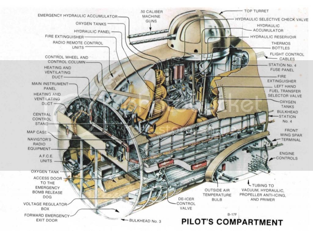
Good evening everyone. For an American on U.S. Memorial Day Weekend I can think of few acts of quiet meditation and remembrance better than building a WWII bomber model. Since I knew half of the crew who flew Luscious Lady, they were on my mind as I worked on this today.

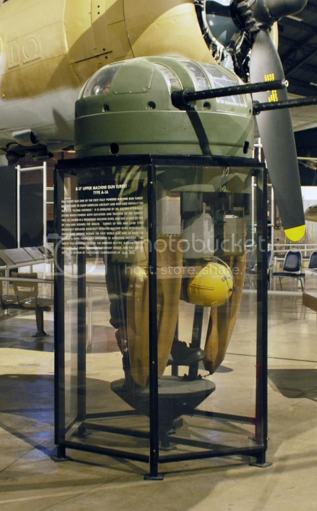
The area of the A/C we're dealing with, the after pilots' compartment, was the "home" of Dale Rice, the crew's engineer and top turret gunner. I never met him but did meet his widow in Rahway, NJ in the 80s. He was reportedly a very inspirational teacher and high school coach after the war.

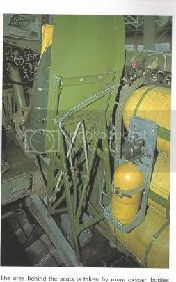
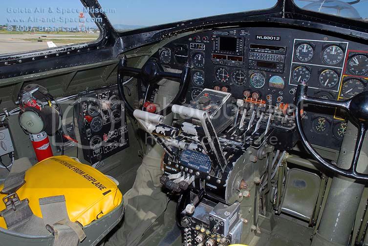
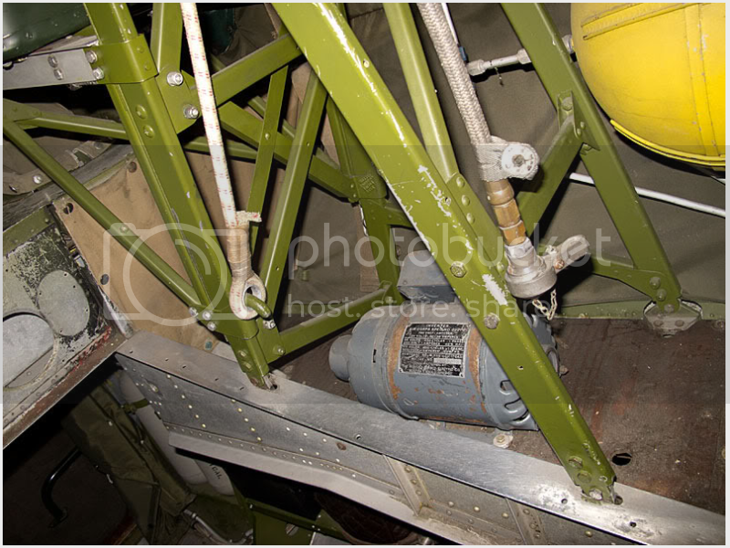
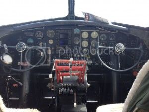
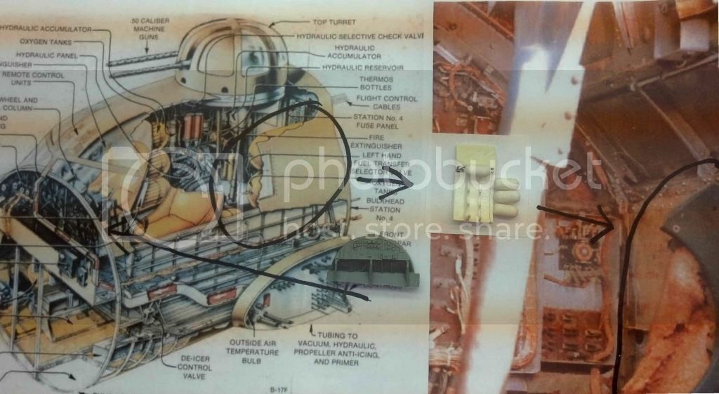
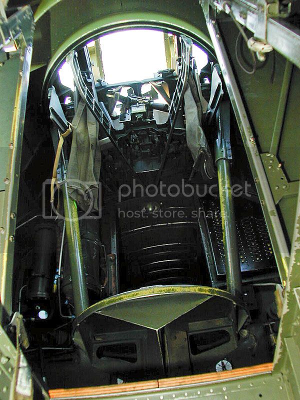
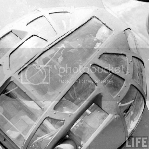
So, I left off with the after bulkhead to the pilots' compartment at the last post. First, I'd like to post a couple of pictures of this area from that "Memphis Belle" photo shoot I relied on before in the nose.

Below you can see the left rear area just to the left of the door to the bomb bay.


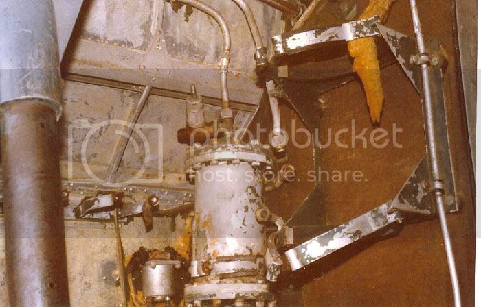
It's in pretty sorry condition and I am happy that the National Museum of the U.S. Air Force in Dayton, Ohio is restoring the A/C after years of neglect. But one thing you can see from this is patches of what sure looks like "bronze green" to me on one of the pieces of hydraulic equipment in the corner. and the bracket for the hydraulic tank to its right.

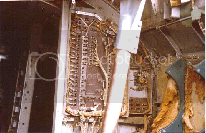
The badly vandalized A/C main fuse panel can be seen to the right of the door in the next picture, along with what appears to be brackets for additional oxygen bottles on the port side. (Not sure if I'll include them in this build.)


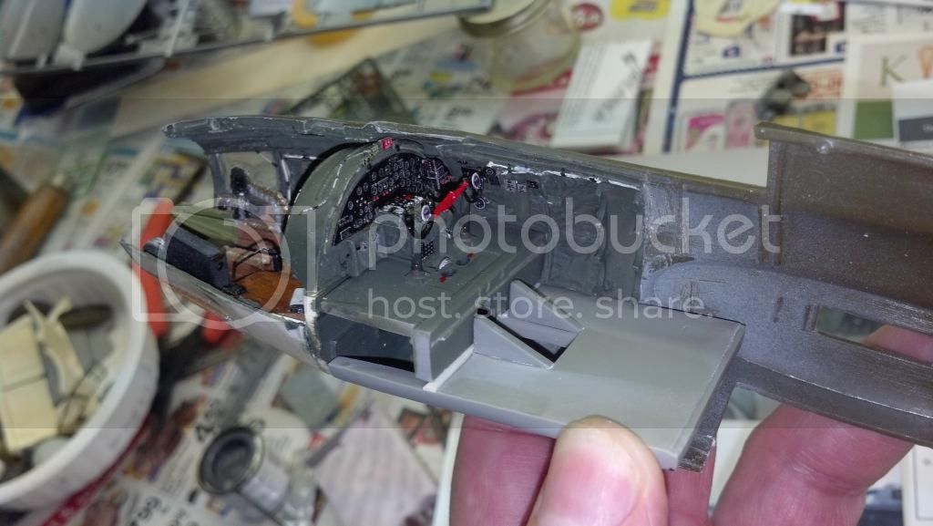
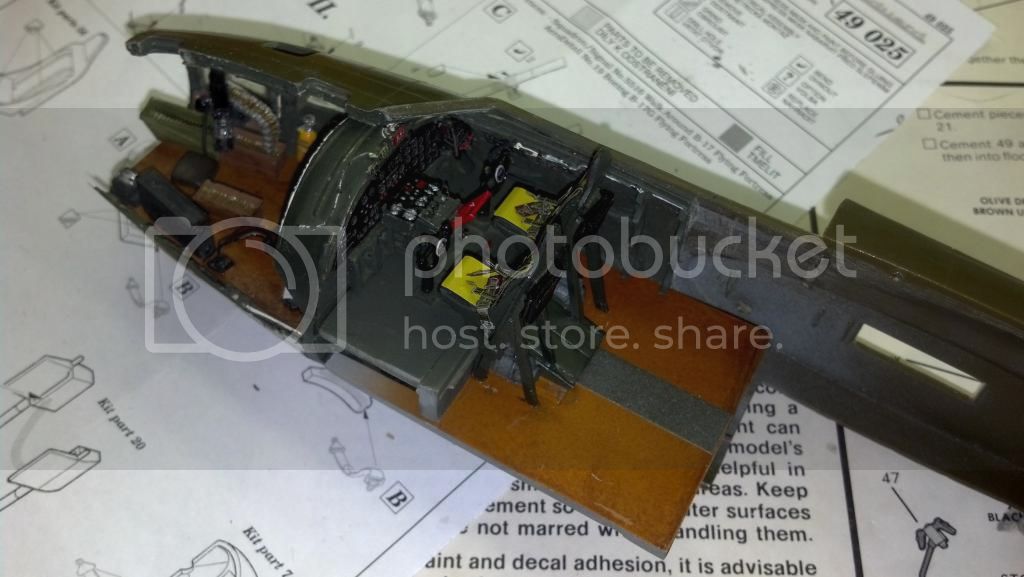
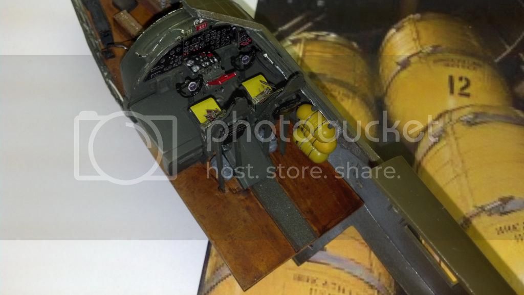
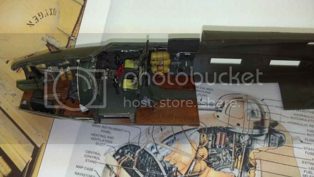
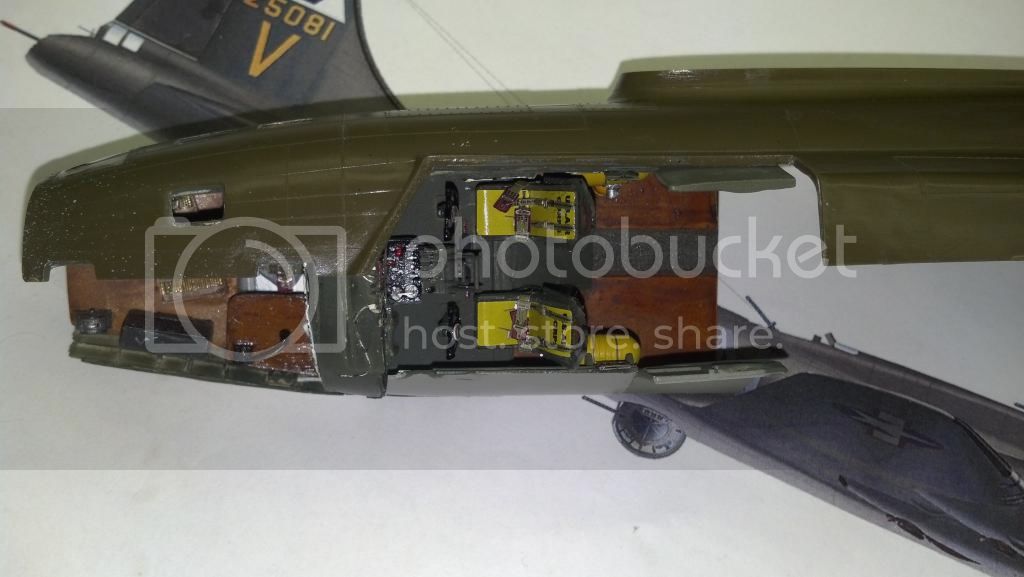
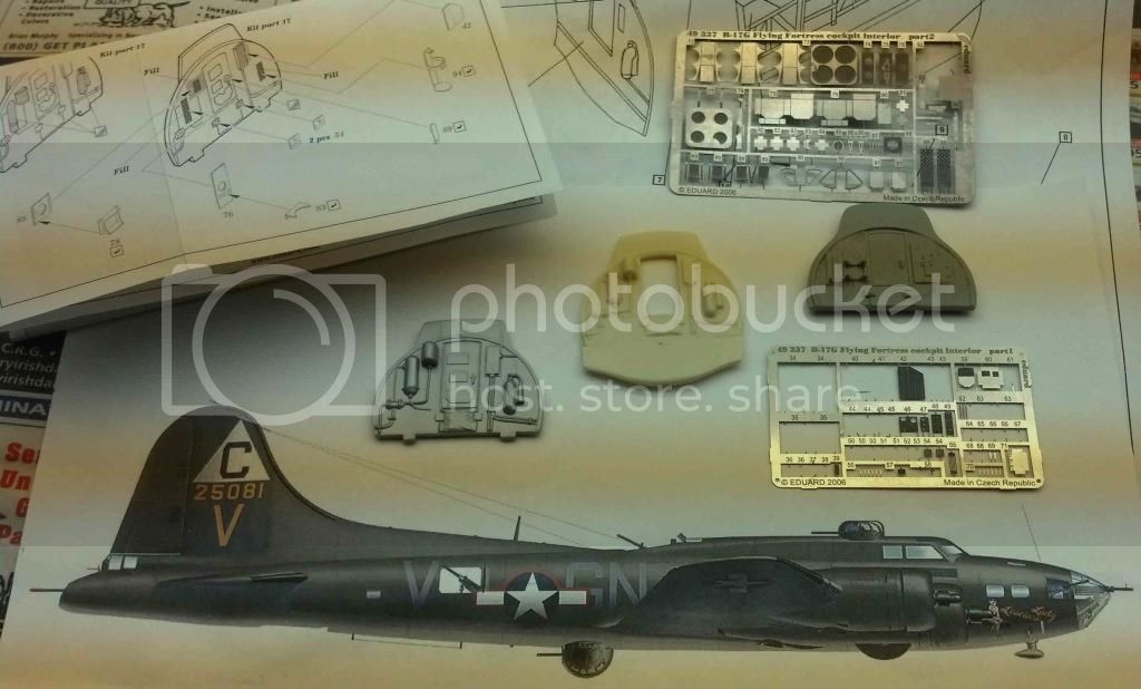
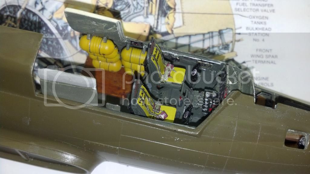
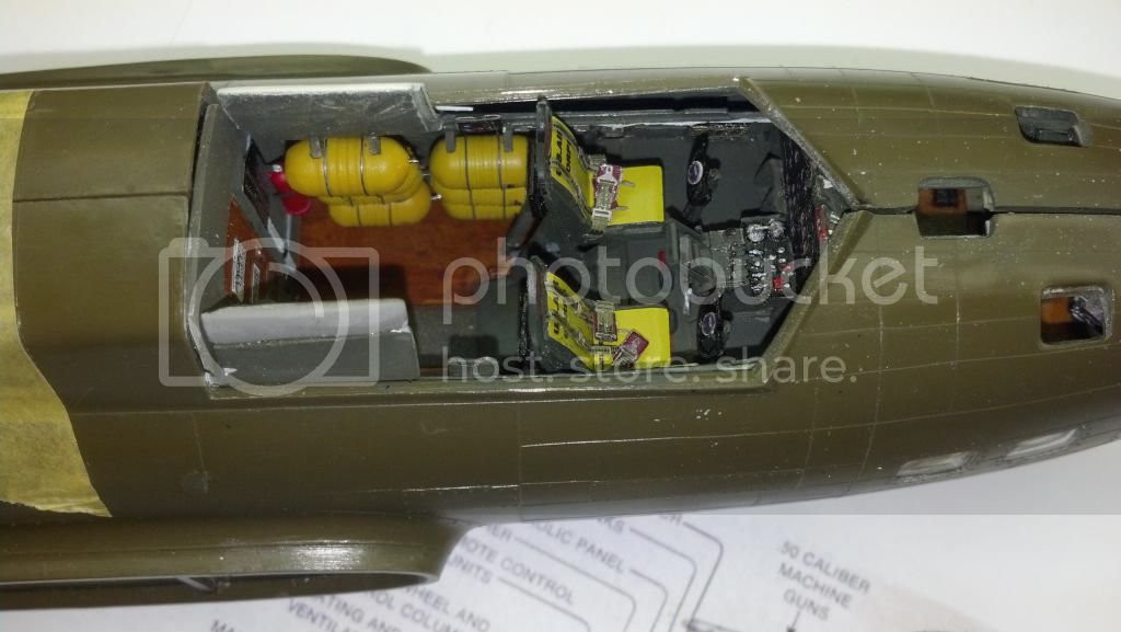
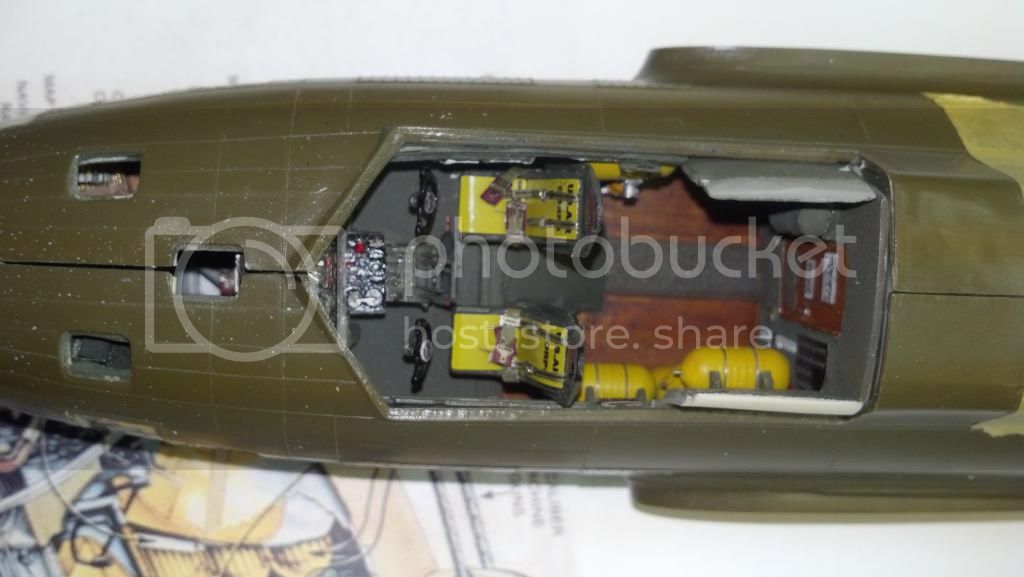
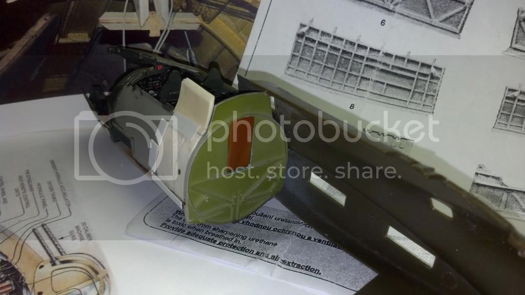
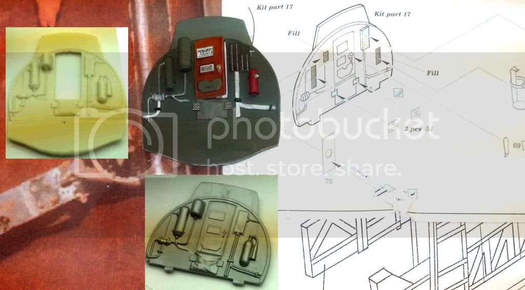
Below you will see how I detailed the after bulkhead, with the left side picture of the "Belle" as a backdrop:


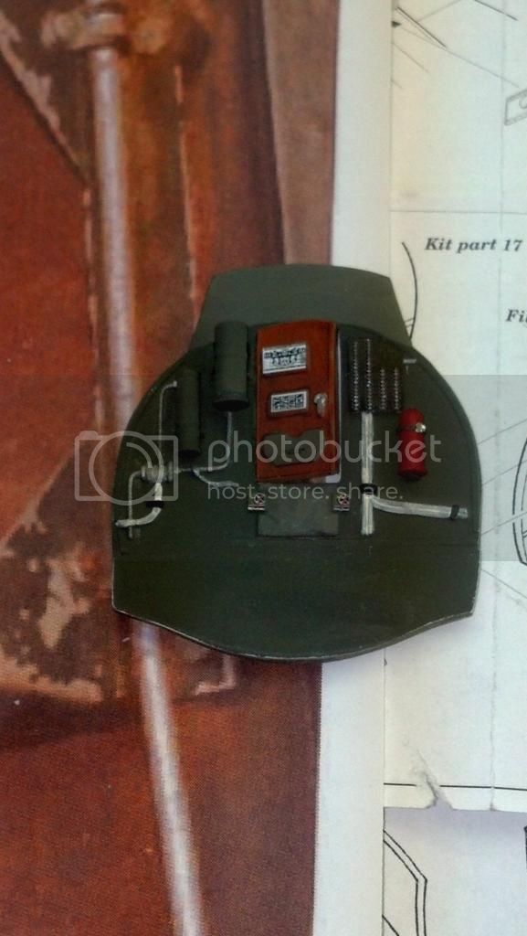
Let me tick off what you are seeing here starting from the left.

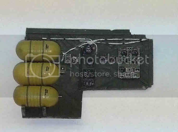
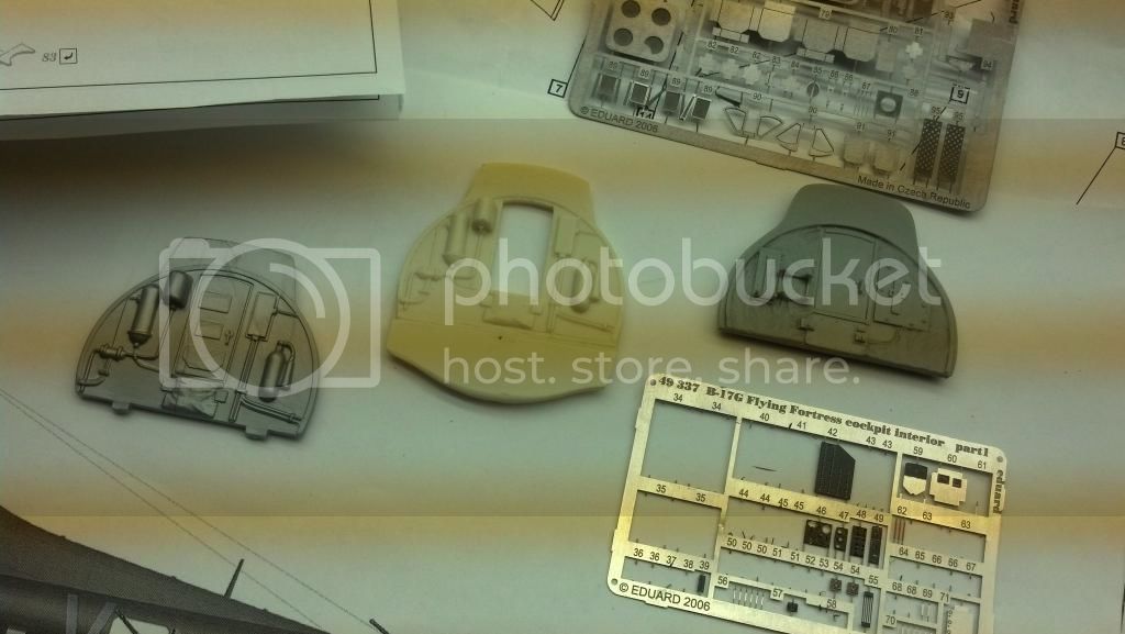
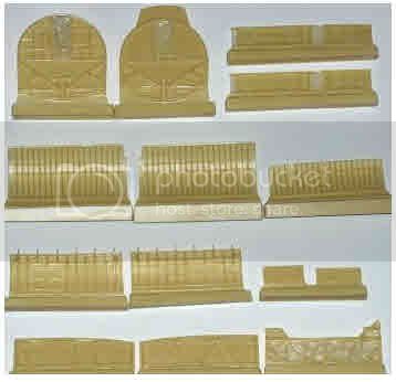
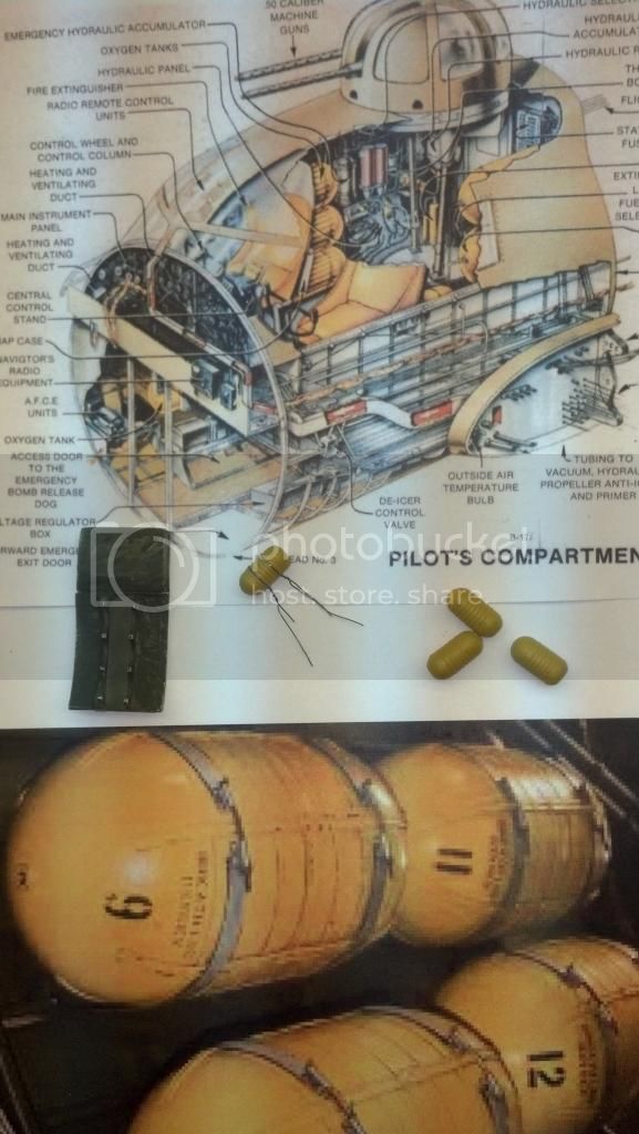
First, the base part is the "Model Detail" after bulkhead from the Czech bomb-bay set I mentioned before. You can see it, and the original Monogram part from the B-17G kit in a "before and after" collage I put together below:


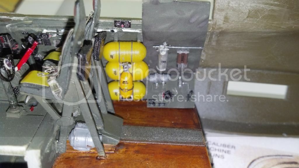
So, moving from left to right:

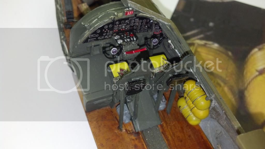
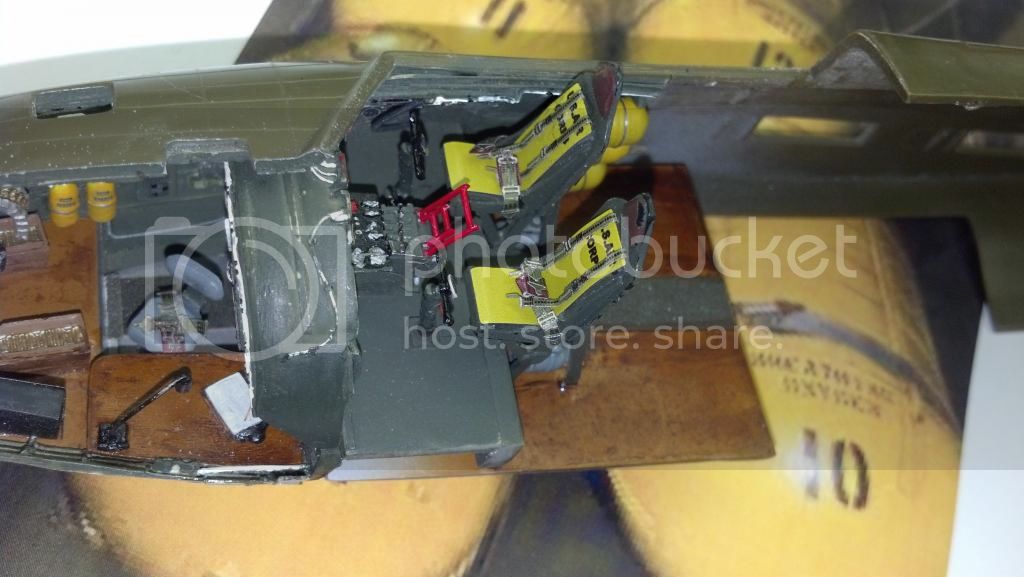
1. The hydraulic piping and valve are silver with white electrical wiring and black cable brackets, as found elsewhere in the A/C.

2. The two pieces of hydraulic equipment to the left of the door are from the True Details cockpit set, and are glued to the Eduard brackets after the kit equivalents were cut off the resin bulkhead. Interestingly enough, Eduard's brass set just gives you the brackets, and doesn't even make reference to the two parts that fit on to them. Strange! To get everything together you really do need both the Eduard cockpit set and the TD one. Note: be careful positioning these two cylinders,, especially the left-most one, to prevent interference with the cockpit side wall.

3. The door was cut out from the Monogram B-17G part. From what I have seen in reference pictures, these doors were plywood and were left in a varnish finish just like the floor. I used the same painting method: wood color, Tamiya clear orange, and craft paint acrylic, burnt umber for weathering. I like the effect, especially with the door fixed partially open. I didn't put a door handle on the door, just painted the molded one that's there: works for me.

4. The two white decals on the door merit special mention. They are from the Revell Germany issue of the B-17F kit, and are simply fantastic. They both look like bomb load/center of gravity charts that a flight engineer like Dale Rice or a ground crew chief would consult while loading the A/C, and are beautiful to behold up close. If you are doing a B-17F build it is worth investing in that kit for the decal sheet alone. It is FANTASTIC, providing a complete stencil set for a B-17F. The third decal is from the spares box. The OD envelope there at the bottom of the door was supposed to contain the aircraft's flight log. The Revell decal wouldn't fit and I prefered to "roll my own."

5. The OD armor plate above the door, the OD envelope at the bottom of the door, and the OD canvas below the door were painted per kit instructions. I like the contrast they provide. The two instruments/control switches below the door are from the Eduard brass set.

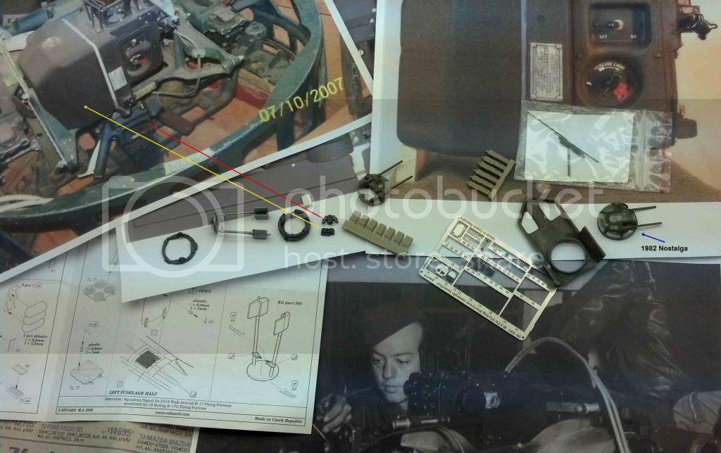
6. To the right of the door the fuse panel is from the Eduard brass set, and the white electrical wiring and black brackets below it and to the right are simply painted.

7. The fire extinguisher bracket is from the Eduard brass set, and the red extinguisher is from the TD set. I am debating whether to add anything to it.

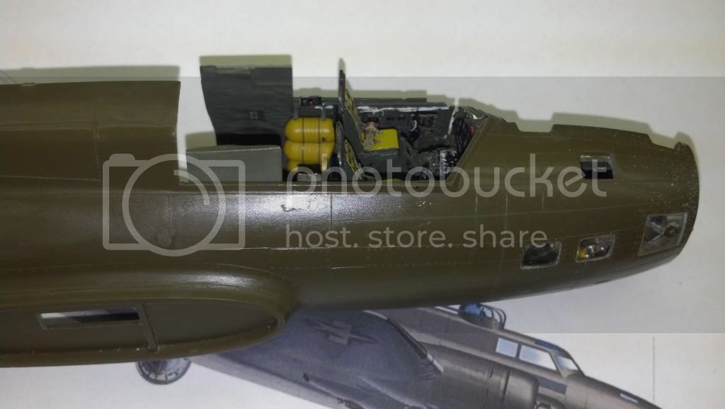
Next time I'll show you the rear bulkhead glued into the right fuselage half, and discuss some other corrections needed to the left rear pilots' compartment.

Happy Memorial Day!

Redhand
#522
_VISITCOMMUNITY
New Jersey, United States
Joined: January 20, 2013
KitMaker: 1,460 posts
AeroScale: 1,443 posts
Posted: Tuesday, May 27, 2014 - 05:04 AM UTC
Last time I said I would "discuss some other corrections needed to the left rear pilots' compartment." I'm going to do that now, and also return to the reason why I substituted the face of the navigator after bulkhead on the Monogram B-17G kit for the one in the TD cockpit set.

Let's go to the left rear pilots' compartment first. Check out the below collage from the B-17F manual and the previously posted shot of "Memphis Belle."


I think it's pretty clear when you look at the Boeing illustration and the interior shot of "Memphis Belle" that there was a second bank of oxygen bottles (four in all) behind the bank of three that is right behind the pilot seat. How can one argue about this from the illustration and the photo?

I had two TD cockpit sets because the first one, in cream resin, was poorly extruded. But it gave me the extra parts to cut and create a second bank of brackets for four bottles. See the parts in the middle. I will add top brackets above the top one, but "you get the idea."

Let's now go to the TD set's depiction of the rear navigator compartment bulkhead (see above photo) and of the same part as depicted in the more recent HK 1/32 scale B-17G. See below:


Frankly, I just couldn't imagine how the kit manufacturers could have put the rear of the pilots' instrument panel instruments sticking out into the navigator's compartment. That would make each instrument into a cylinder well over a foot long!!

However, if you look at the Boeing illustration above you will see what I think this depiction in 2-D reflects: an obvious "cut-away" to reveal the rear of the instrument panel with an attempt at three-dimensionality through the arch of the wiring at the left, and a more subtle attempt to depict open space below the wiring. But, since the rear of the instrument panel is black as is the area below it, it looks like a flat surface mating right on top of the forward wood section. Sort of reminds me of this picture


and an effort to make it into a 3-D model. It doesn't work very well, does it? Anyone disagree?

More later as I continue with the left rear pilots' compartment wall and those four additional oxygen bottles.
thegirl
_VISITCOMMUNITY
Alberta, Canada
Joined: January 19, 2008
KitMaker: 6,743 posts
AeroScale: 6,151 posts
Posted: Tuesday, May 27, 2014 - 11:15 AM UTC
Now this is my kind of building , very well done


Terri
Redhand
#522
_VISITCOMMUNITY
New Jersey, United States
Joined: January 20, 2013
KitMaker: 1,460 posts
AeroScale: 1,443 posts
Posted: Tuesday, May 27, 2014 - 11:33 AM UTC
Thx Terri. The building makes the point about the mistaken literalness of the kit designers, and I like the pun in your post too!

I'm not going to try and do everything in this build, but I want the cockpit to be accurate enough that people will say, "Yeah, he made a real effort to get it right."
FredrikA
_VISITCOMMUNITY
Uppsala, Sweden
Joined: January 09, 2008
KitMaker: 92 posts
AeroScale: 90 posts
Posted: Tuesday, May 27, 2014 - 05:38 PM UTC
Brian, I think that many of us already think that you've done a real effort! Fantastic work on the model as well as on your presentation of it to us! Can't wait for more updates.

/Fredrik
Redhand
#522
_VISITCOMMUNITY
New Jersey, United States
Joined: January 20, 2013
KitMaker: 1,460 posts
AeroScale: 1,443 posts
Posted: Wednesday, May 28, 2014 - 03:19 PM UTC

Quoted Text

Brian, I think that many of us already think that you've done a real effort! Fantastic work on the model as well as on your presentation of it to us! Can't wait for more updates.

/Fredrik


Thank you Fredrik. I did a bit of work on the additional oxygen bottles tonight, and the port after bulkhead, and I have been studying up on the top turret configuration, in particular the K-3 gun-sight. Here is a really interesting site that has pictures of it and a description how it worked. http://www.aircraft-gunsights.com/k-series-sights/.

I actually dealt with WWII technology similar to this many years ago when I was in the US Navy (NOT during WWII I assure you!) and will "talk that up" as I describe whatever it is I decide to do with the kit part depicting it.

Thanks again for the kind words.

Brian
Joel_W
Staff MemberAssociate Editor
AUTOMODELER
_VISITCOMMUNITY
New York, United States
Joined: December 04, 2010
KitMaker: 11,666 posts
AeroScale: 7,410 posts
Posted: Thursday, May 29, 2014 - 02:50 AM UTC
Brian,
I've been following your excellent build from day 1. Your work is exceptional to say the least. How you combine your research to your build makes following along so enjoyable.
The detailing on the rear bulkhead is a perfect example.

The picture you posted just draws you into it. I've been staring at it, and the longer you do, the more you see. It's rather weird to say the least.

As usual, looking forward to your next update.

Joel
Redhand
#522
_VISITCOMMUNITY
New Jersey, United States
Joined: January 20, 2013
KitMaker: 1,460 posts
AeroScale: 1,443 posts
Posted: Thursday, May 29, 2014 - 11:35 AM UTC
Thank you!! More soon.
Redhand
#522
_VISITCOMMUNITY
New Jersey, United States
Joined: January 20, 2013
KitMaker: 1,460 posts
AeroScale: 1,443 posts
Posted: Saturday, May 31, 2014 - 12:40 PM UTC
B-17 Cockpit Completed (Except for Roof & Top Turret)

I found time today to get the pilots' compartment done, finally! Here are some views as work progressed.

The first view shows how I attach securing bands to the oxygen bottles, as well as the modified and painted after port bulkhead


The next view is of that bulkhead and four bottles installed behind the forward bank of three in the model.


Next we have essentially the same shot with the after bulkhead installed and the fuselage taped together. Note that I glued the door to the bomb-bay closed. Some additional photo research showed the door opening inward into the bomb bay. The fit forward is loose and the gap near the pilot's seat will disappear when the halves are glued together.


Next we have an overhead shot showing how it all fits together. I do like the after floor and overall "used" effect.


Finally there is a shot showing the bomb-bay side of the after bulkhead. I will be adding hinges and a door handle on the closed door.


I test fit the cockpit roof and the turret, including the piece extending down to the floor. They fit, but just barely. Looking at the compartment with all those oxygen bottles, I am impressed by how utterly tight and claustrophobic the space was -- not to mention the risk of explosion and fire if an incendiary round exploded there.

Next up -- the cockpit roof and this top turret:

Redhand
#522
_VISITCOMMUNITY
New Jersey, United States
Joined: January 20, 2013
KitMaker: 1,460 posts
AeroScale: 1,443 posts
Posted: Wednesday, June 04, 2014 - 09:17 AM UTC
As you might guess from the last picture in the prior post, I plan to do more with the top turret than just glue and paint kit parts. The turret is really a "little kit" in and of itself, just as this build is a succession of "little kits" when you think of it. (I believe that's the only way to get past the idea that you're devoting tons of time to just "one model.")

Anyway, there's a lot going on with the top turret. The below picture shows the "plan of attack," with an initial focus on the Sperry K-3 gunsight between the twin .50s.


The yellow arrow compares the K-3 sight to the tiny kit part, which I cut out from the Monogram part. That had the sight, the guns and two ammo feeds all glopped together, similar to the Revell kit counterpart you see in the picture, in the center. In fact, the "kit" gunsight is only the top half of the real thing. I need to add a bottom to it.

The red line leads from the real turret controller to the chin turret controller cut from the Monogram kit part. That is very similar to the top turret controller, but needs some additional mods, as will to be discussed later.

Finally, the blue line ("1982 Nostalgia") is sad evidence of my one prior build of the Revell B-17F 1/48 kit, all painted up to represent "Yankee Doodle Dandy," the B-17E Gen. Ira Eaker flew in in the first B-17 raid over Europe, Rouen, France, 8/17/42. I used an early Koster conversion set for it back around 1982, but it didn't survive a close encounter with the family cat.

The following three pictures give you some idea of the territory we'll be covering in the turret build:


Note the man's head at the rear of the turret canopy. Pretty tight quarters!