World War II
Discuss WWII and the era directly before and after the war from 1935-1949.
Hosted by Rowan Baylis
1/48 B-17F Build - 303rd BGs Luscious Lady
Redhand
#522
_VISITCOMMUNITY
New Jersey, United States
Joined: January 20, 2013
KitMaker: 1,460 posts
AeroScale: 1,443 posts
Posted: Friday, August 30, 2019 - 11:24 PM UTC
WELL, WELL, WELL


H.G.'s work on the wheel wells continues unabated. I'll take you through it as I discovered the details.

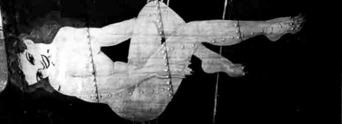
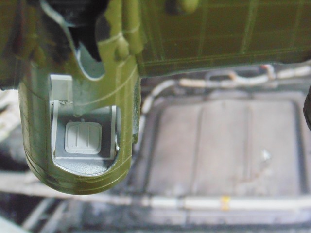
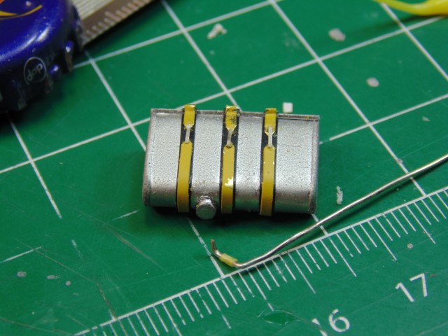
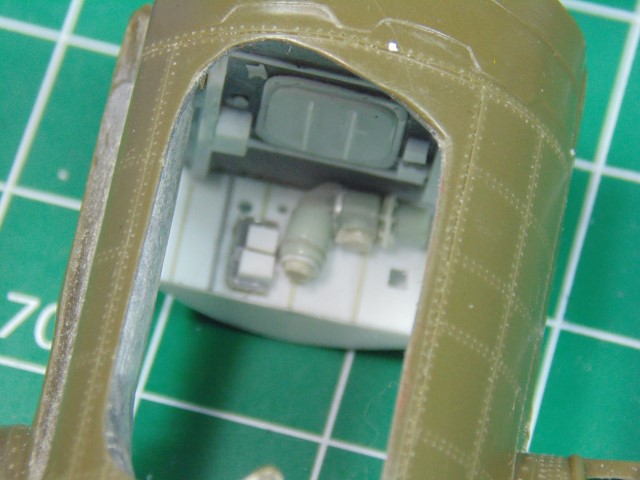
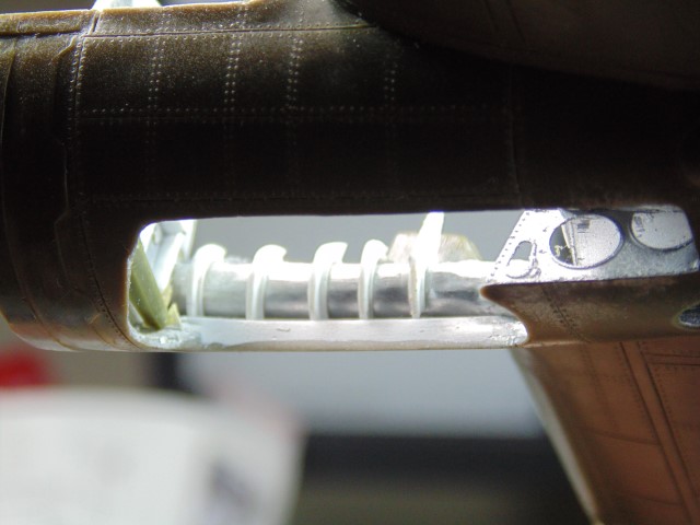
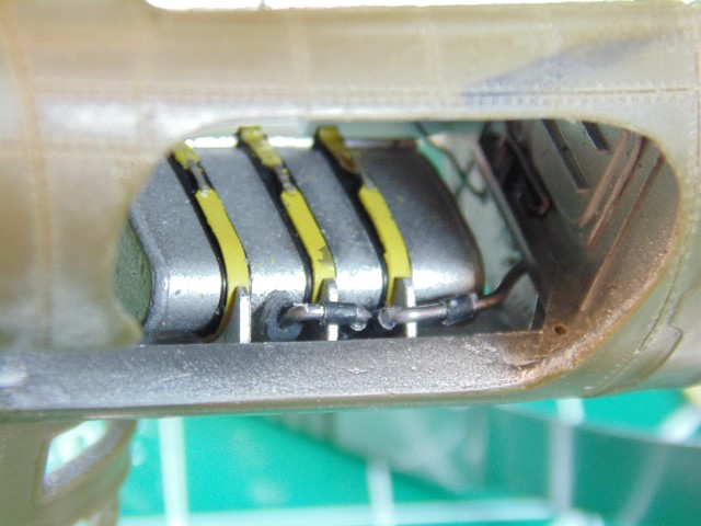
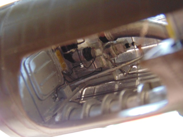
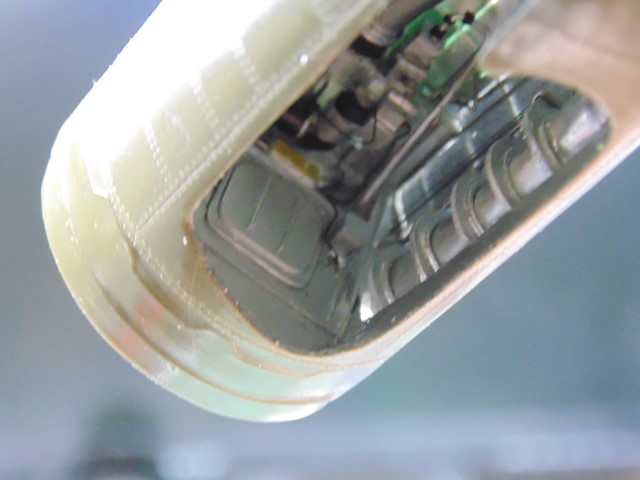
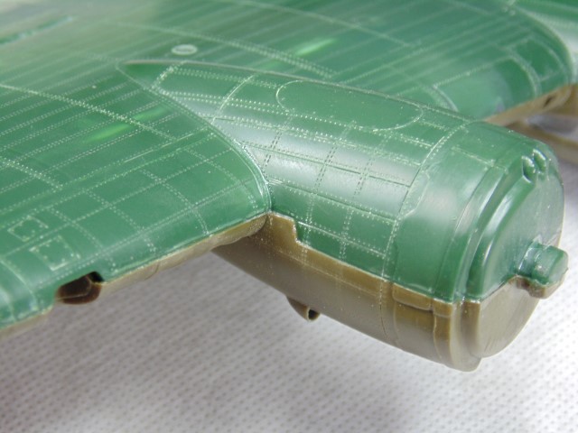
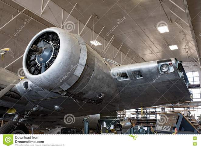
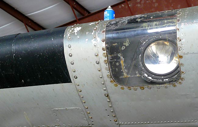
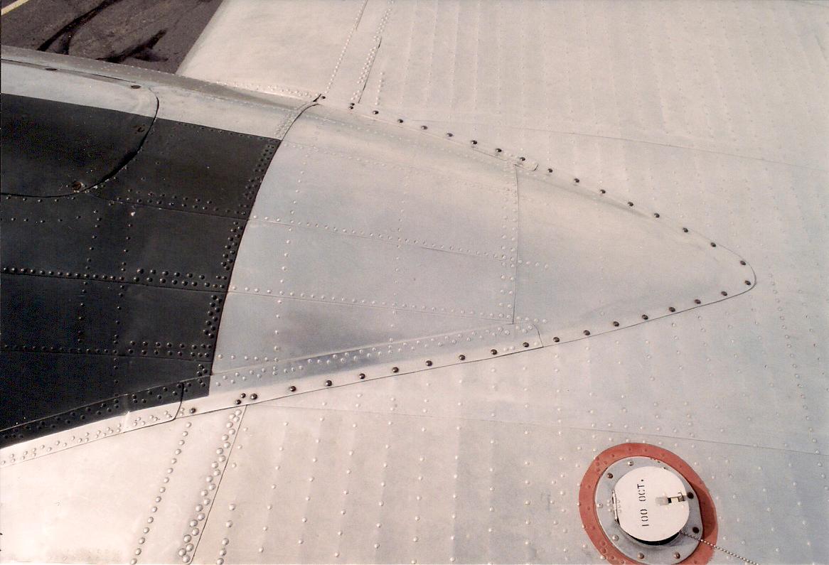
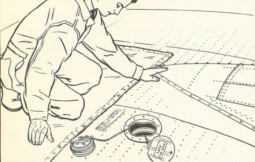
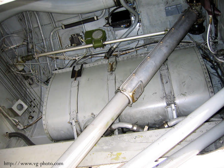
First, a refresher on what the engine oil tank looks like.

And, BTW, don't forget that large landing strut in the foreground cutting diagonally across the tank. I will return to that later.


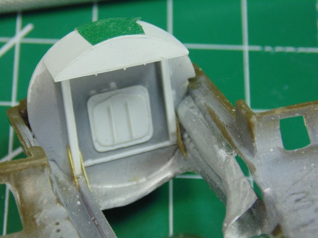
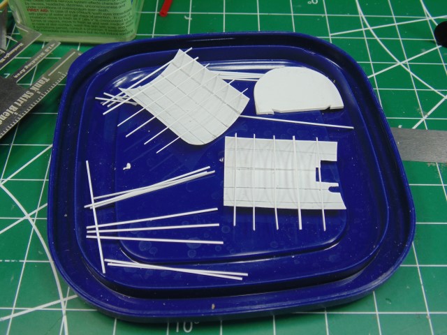
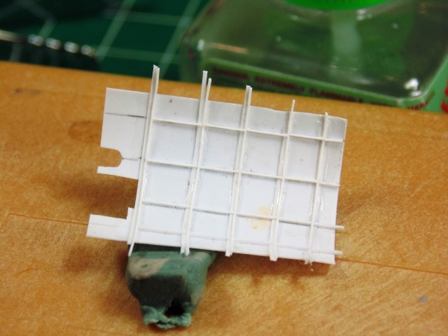
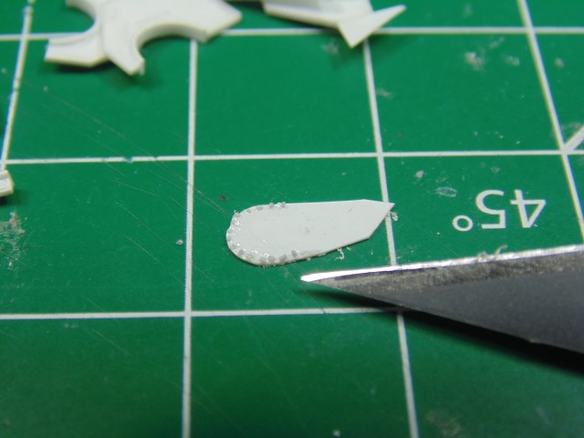
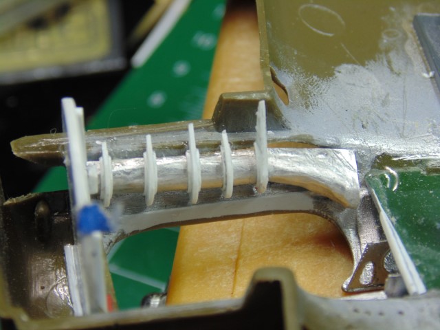
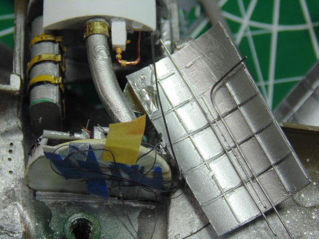
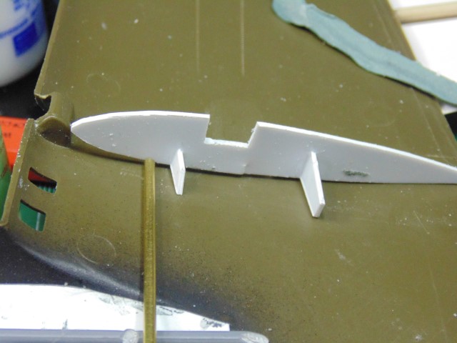
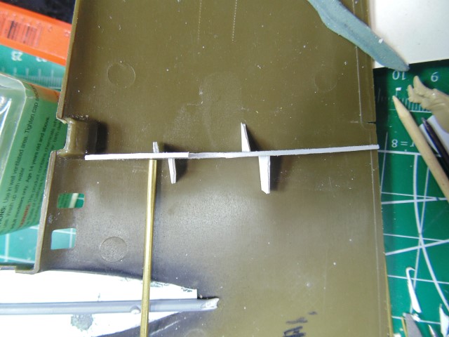
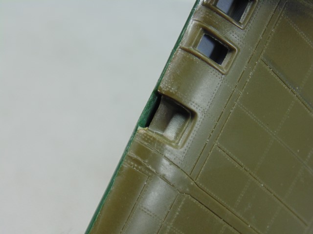
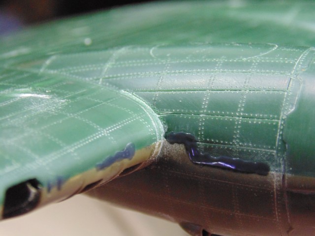
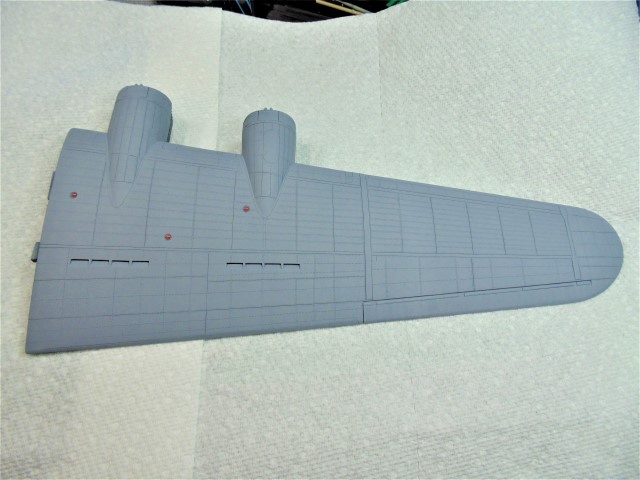
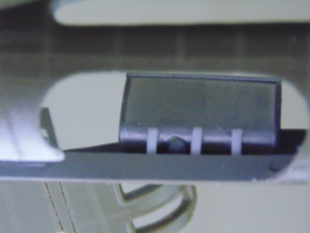
What are these styrene cut-outs, you might ask? I did.


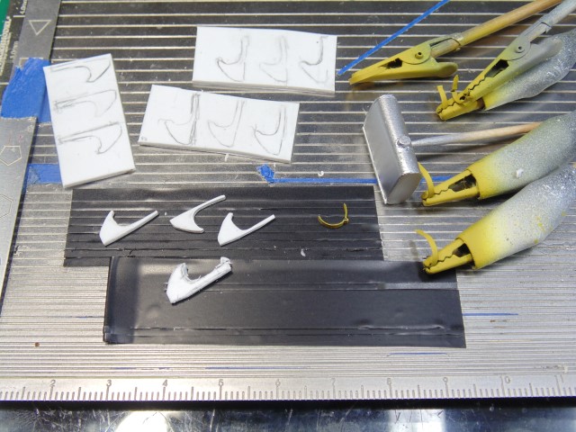
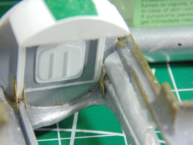
Why, the "J" shaped brackets to hold the oil tanks in place, of course!
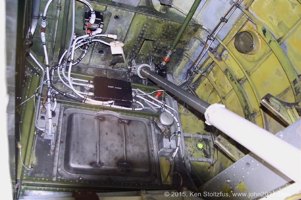
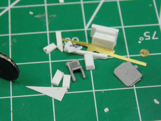
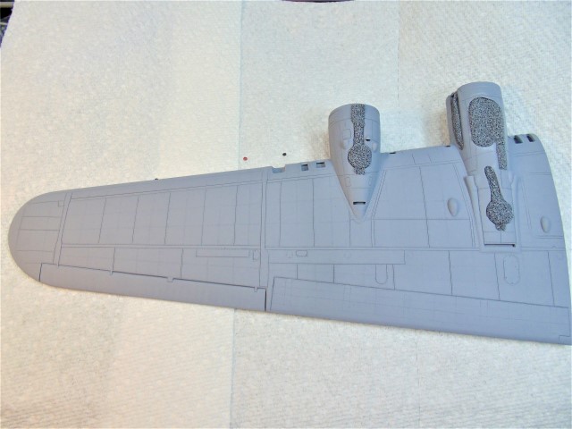


Look to the right.

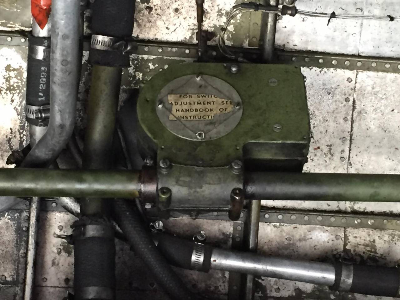
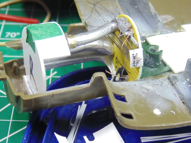
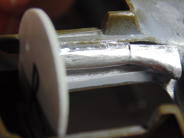
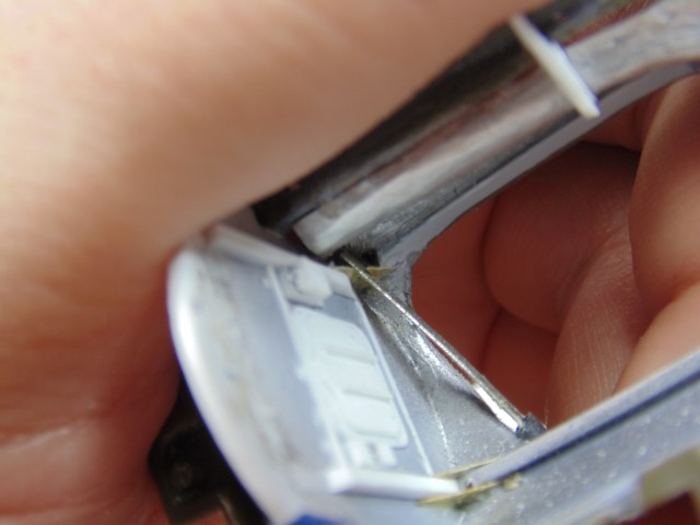
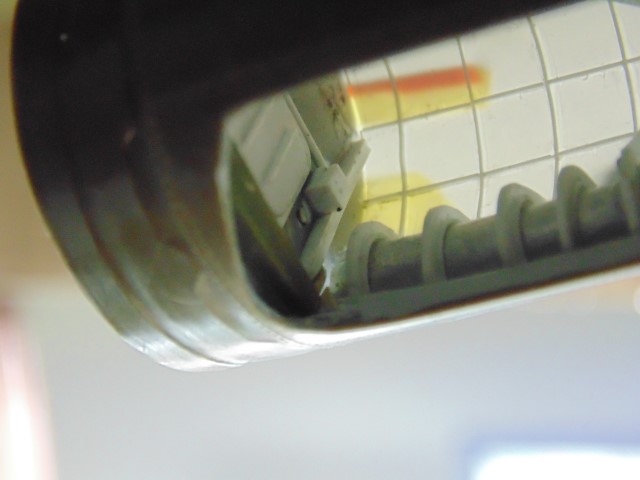
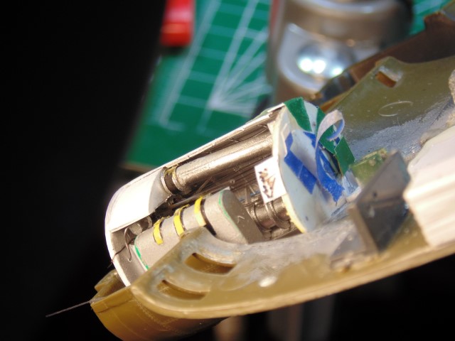
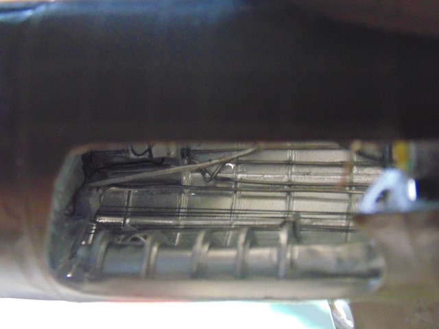
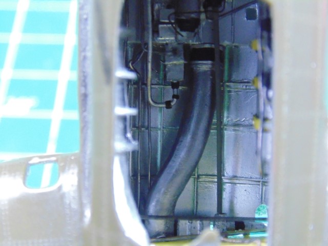
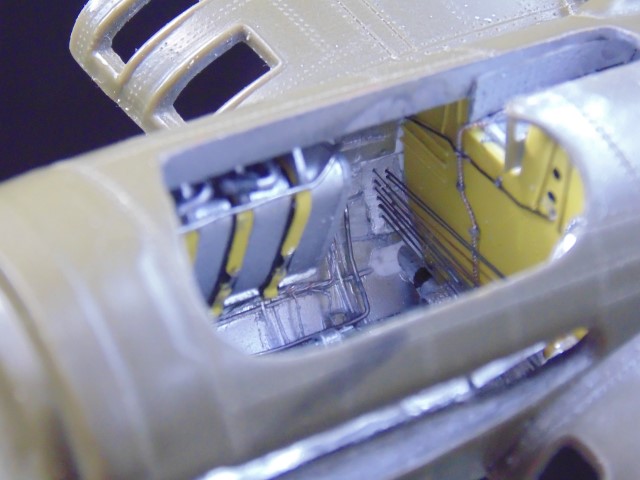
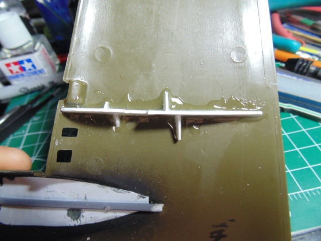
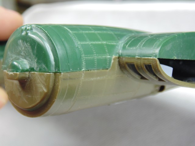
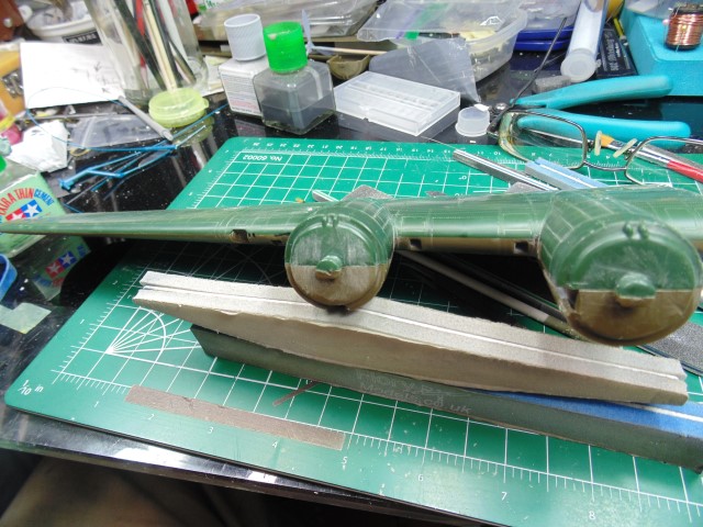
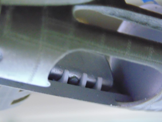
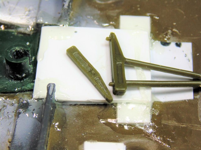
This picture is also interesting because the upper part of the long retracting strut is unsheathed. Compare it with the preceding real-thing photo.

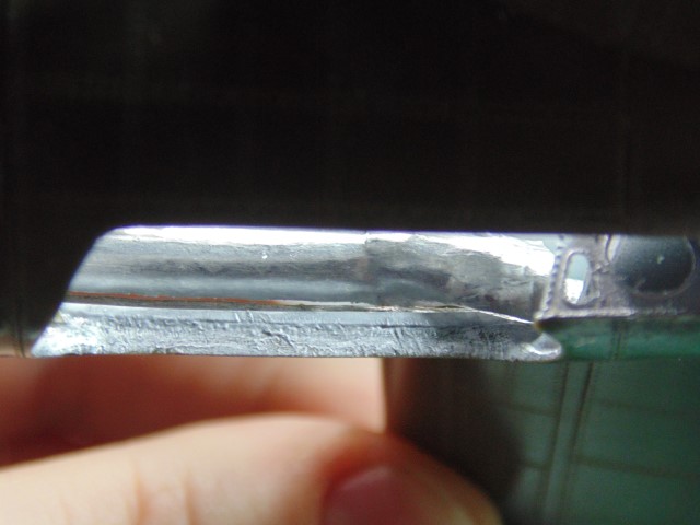
Earlier I had asked, rhetorically, if this section of the landing gear mechanism was a "ballscrew." Here we can see that the answer is plainly "yes." From the prior real-thing photo, we can see that the ballscrew is covered by a two-part sheath or cover and that the lower part of the retracting strut goes inside the sheath when the gear is raised. (I think, I mean it has to, no??) More on this later.

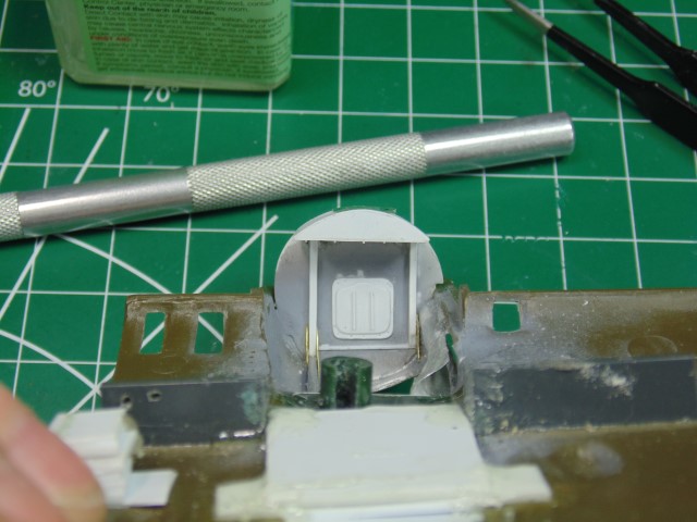
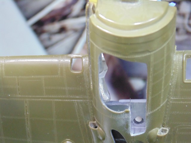
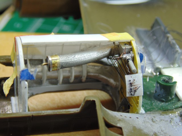
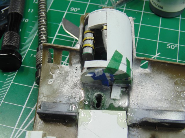
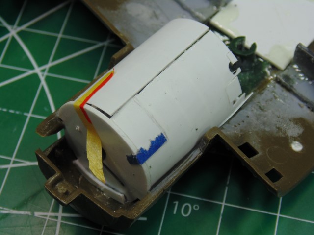
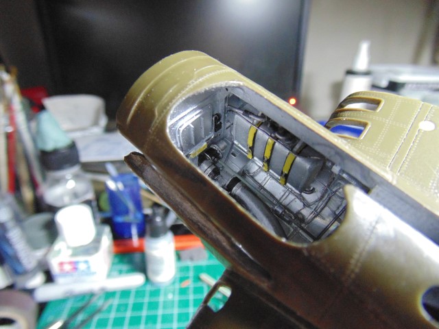
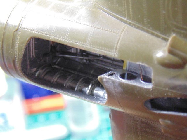
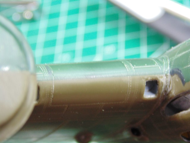
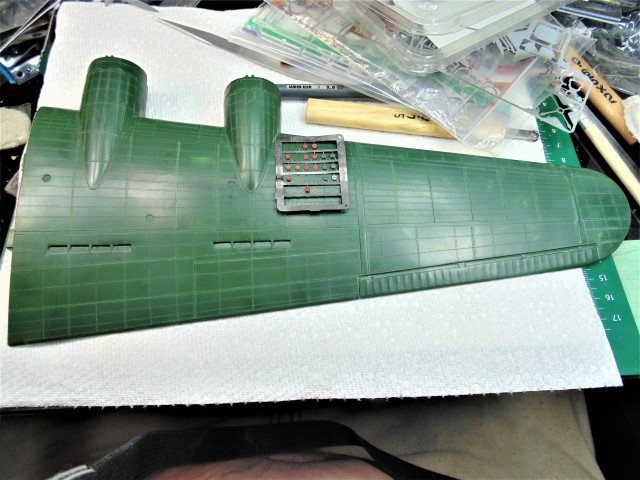
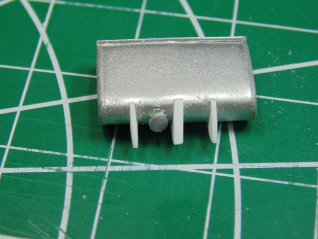
Let's return to the oil tank. Here you can see the "J" brackets fitted to it -- they are NOT finished or fully shaped yet. This is just to provide "a look."


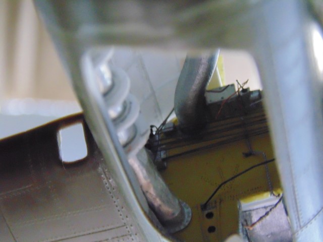
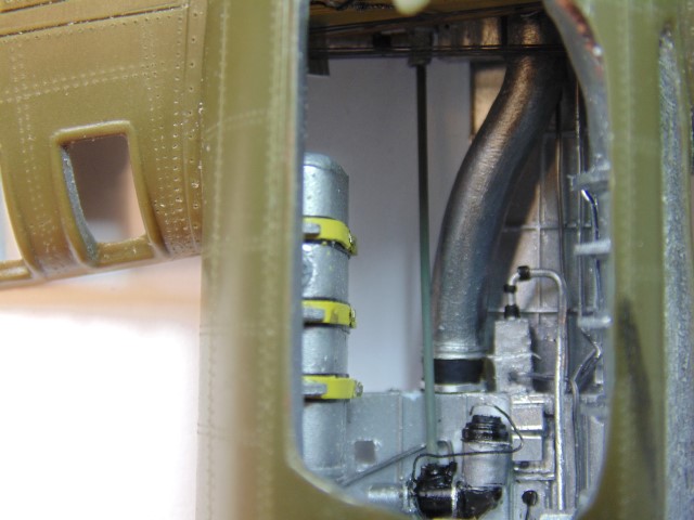
Here are two shots of the tank seated on the "J" brackets inside the nacelle.


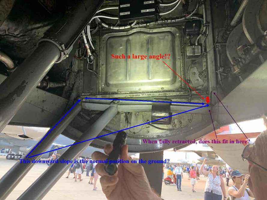
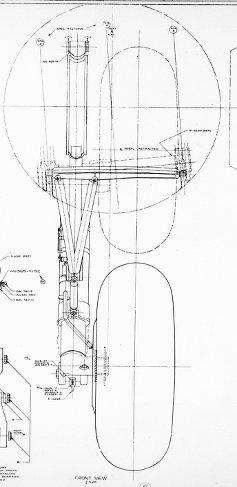
And now back to the landing gear retracting shafts. This diagram is courtesy of Karl (of course):


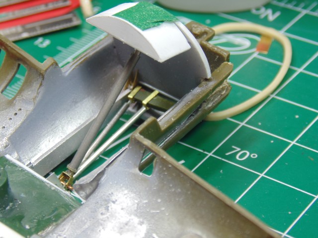
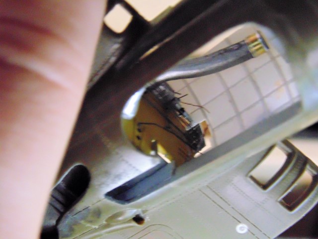
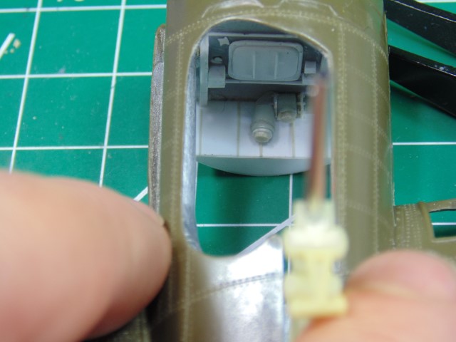
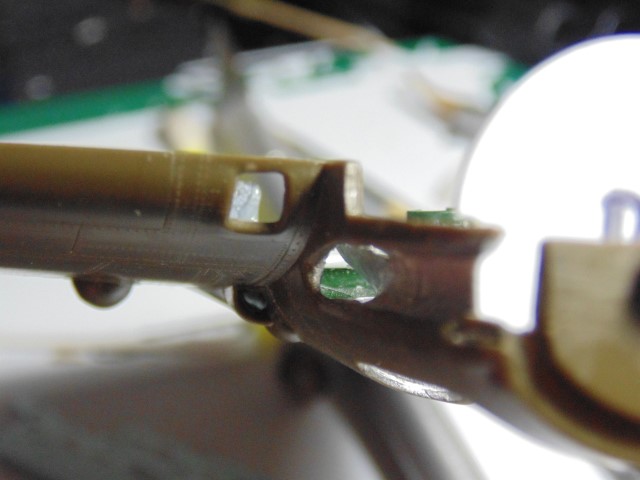
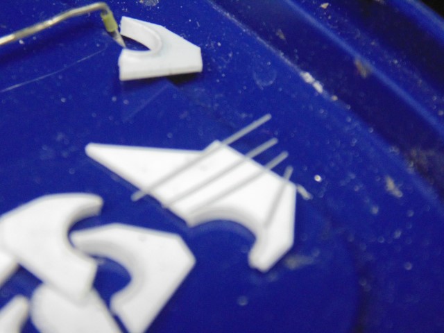
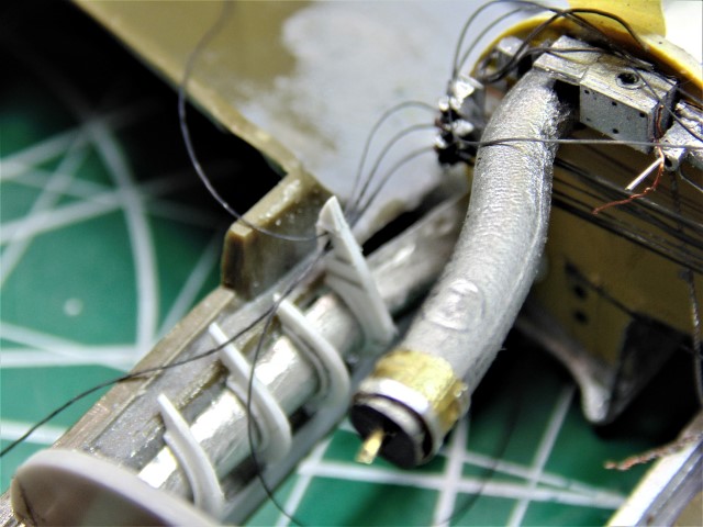
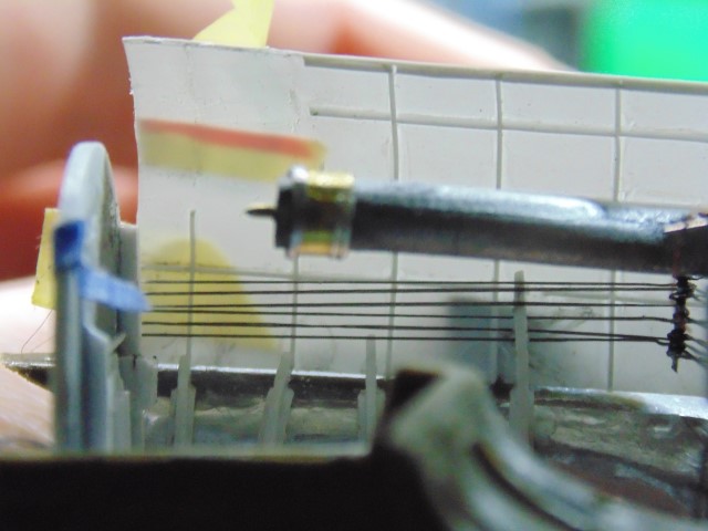
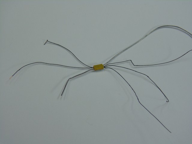
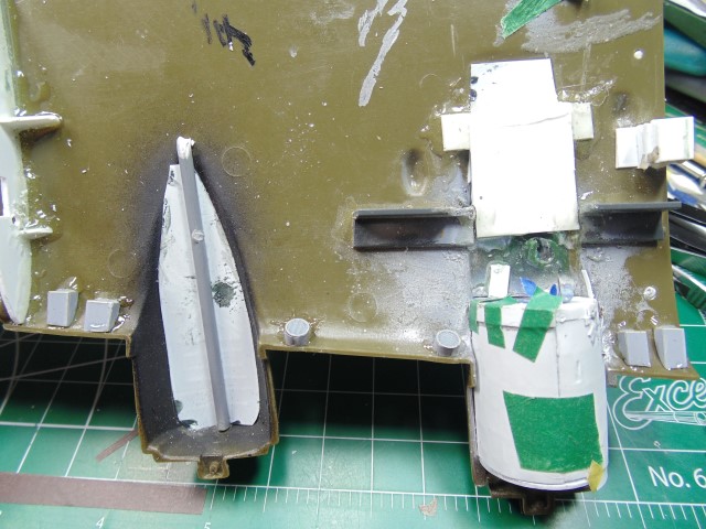
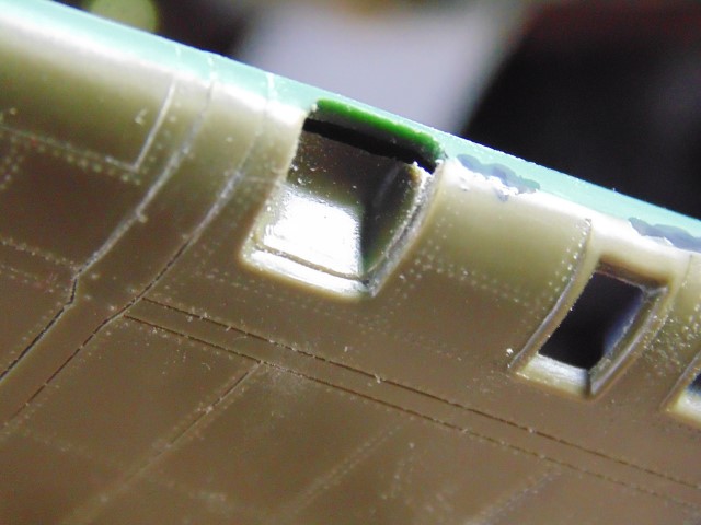
It took me a while to figure out where the three metal legs that H.G. scratch-built were going to interface with the kit parts.

A picture is worth a thousand words.
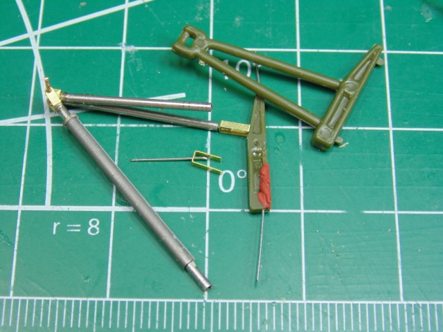
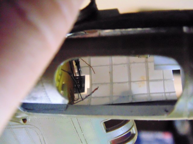


Man, oh man!

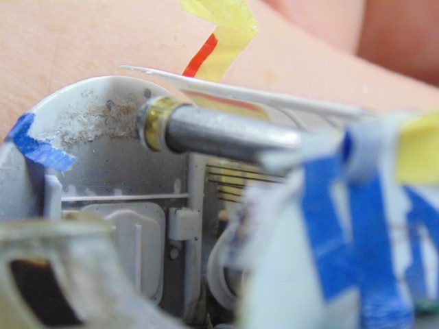
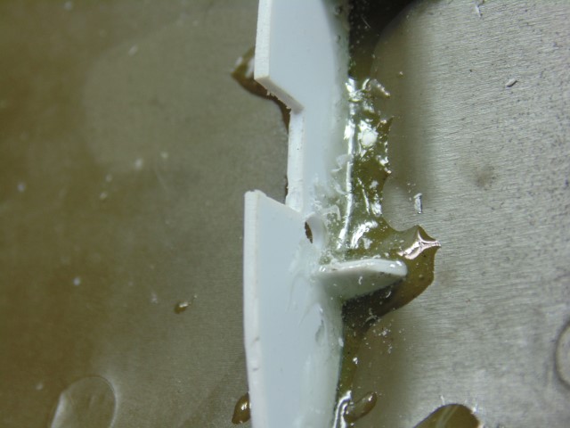
You see that H.G. is also thinning the plastic piece.


What a great way to start U.S. Labor Day Weekend!
amoz02t
#192
_VISITCOMMUNITY
Kentucky, United States
Joined: November 25, 2009
KitMaker: 1,383 posts
AeroScale: 65 posts
Posted: Saturday, August 31, 2019 - 12:14 AM UTC
Brian- You guys are doing wonderful work. Thank you for providing great insight into how things worked! Also...Randy Malmstrom offered up more gear bay photos at this website here...

https://www.facebook.com/groups/1659466480983634/2322846911312251/?comment_id=2324068184523457&reply_comment_id=2324123627851246¬if_id=1567186487180359¬if_t=group_comment

He is on fb as well. All the best-S
Joel_W
Staff MemberAssociate Editor
AUTOMODELER
_VISITCOMMUNITY
New York, United States
Joined: December 04, 2010
KitMaker: 11,666 posts
AeroScale: 7,410 posts
Posted: Saturday, August 31, 2019 - 01:03 AM UTC
Brian,
Clearly HG is still modeling at the top of his game.
Joel
Redhand
#522
_VISITCOMMUNITY
New Jersey, United States
Joined: January 20, 2013
KitMaker: 1,460 posts
AeroScale: 1,443 posts
Posted: Saturday, September 07, 2019 - 05:26 AM UTC
MOTHERLODE

When it comes to sheer artistry, I think what is shown in this post will rank up there among the best in the whole blog.

HG spent considerable time figuring out the exact angle at which the "angle iron" cross piece connecting the retraction shafts of the main landing gear fit across the front of the wheel well bay. You can see what I'm talking about by the strange apparent angle downward and to the right in the below photo.


The annotations in the picture are mine and reflect questions that I asked Karl to assist HG in positioning the part. The "downward angle" is incredibly tricky to interpret because there is the angle that the photographer is taking the picture, the dihedral of the wing, and the overall dimensions of the wheel well bay sides themselves to take into consideration.

The ultimate conclusion was that this was something of an optical illusion and that the "angle iron" part should be fit in such a way that the gear "looks right" from the outside, with the internal wheel well components appearing either perpendicular or parallel to the ground.

Adjustments are still necessary but you can see better what I'm talking about in 1/48 scale below.


Additional positioning is necessary but the amazing thing is that HG has actually constructed a retraction mechanism that moves! Of course, it will have to be fixed in the fully extended position in the final build.

If you are like me, the accumulated detail in the following pictures will be overwhelming.


We are now moving to the wheel well front bulkhead. Little commentary as necessary. The pictures say at all.


What follows is even better because it includes sidewall ribbing detail.


Here are some examples of how he put the sidewalls together.


More to follow but I can literally say that I have never seen a B-17 build like this before.
Joel_W
Staff MemberAssociate Editor
AUTOMODELER
_VISITCOMMUNITY
New York, United States
Joined: December 04, 2010
KitMaker: 11,666 posts
AeroScale: 7,410 posts
Posted: Saturday, September 07, 2019 - 07:04 AM UTC
Brian,
Honestly, none of us has. This is beyond even what I've seen accomplished at IPMS National conventions. As I've said time and time again, HG just has to be an Alien as his skills and mind set are far above anything I've ever seen.

You might want to start to think about donating this incredible build to an Aviation museum. Naturally, a full set of detail pictures, a base with a face made from a mirror, and a custom glass cover.

Joel

amoz02t
#192
_VISITCOMMUNITY
Kentucky, United States
Joined: November 25, 2009
KitMaker: 1,383 posts
AeroScale: 65 posts
Posted: Sunday, September 08, 2019 - 12:54 PM UTC

Quoted Text

MOTHERLODE

When it comes to sheer artistry, I think what is shown in this post will rank up there among the best in the whole blog.

HG spent considerable time figuring out the exact angle at which the "angle iron" cross piece connecting the retraction shafts of the main landing gear fit across the front of the wheel well bay. You can see what I'm talking about by the strange apparent angle downward and to the right in the below photo.


The annotations in the picture are mine and reflect questions that I asked Karl to assist HG in positioning the part. The "downward angle" is incredibly tricky to interpret because there is the angle that the photographer is taking the picture, the dihedral of the wing, and the overall dimensions of the wheel well bay sides themselves to take into consideration.

The ultimate conclusion was that this was something of an optical illusion and that the "angle iron" part should be fit in such a way that the gear "looks right" from the outside, with the internal wheel well components appearing either perpendicular or parallel to the ground.


This is amazing work on the LL! So much fun to see the art and thank you for sharing. I wanted to comment on the optical illusion from the camera. Yes. This gear bay picture was taken quickly with an iPhone XR with lighting from my flashlight as shown at Oshkosh 2019. I do not typically see any "fisheye" effects from the phone camera, but I agree there must be distortion. Sorry I did not pay more attention to the potential odd angles. Following closely- All the best - S
Redhand
#522
_VISITCOMMUNITY
New Jersey, United States
Joined: January 20, 2013
KitMaker: 1,460 posts
AeroScale: 1,443 posts
Posted: Sunday, September 08, 2019 - 02:43 PM UTC

Quoted Text

I wanted to comment on the optical illusion from the camera. Yes. This gear bay picture was taken quickly with an iPhone XR with lighting from my flashlight as shown at Oshkosh 2019. I do not typically see any "fisheye" effects from the phone camera, but I agree there must be distortion. Sorry I did not pay more attention to the potential odd angles. Following closely- All the best - S


How mind-blowing that your photo appears in the build blog! Who could have imagined that!?

I'm pleased you are enjoying the progress. I agree we are seeing wonderful things at this stage.

Brian
GazzaS
#424
_VISITCOMMUNITY
Queensland, Australia
Joined: April 23, 2015
KitMaker: 4,648 posts
AeroScale: 1,938 posts
Posted: Sunday, September 08, 2019 - 02:51 PM UTC
Some fabulous upgrading here!
Redhand
#522
_VISITCOMMUNITY
New Jersey, United States
Joined: January 20, 2013
KitMaker: 1,460 posts
AeroScale: 1,443 posts
Posted: Monday, September 09, 2019 - 12:56 PM UTC
ACCUMULATION OF DETAIL

More to see in the wheel wells.

An oil tank with new details.


Love the yellow securing straps with the rubber cushions behind.

Parts awaiting further finishing and their place in the nacelle.


The details grow,


step by step:
Joel_W
Staff MemberAssociate Editor
AUTOMODELER
_VISITCOMMUNITY
New York, United States
Joined: December 04, 2010
KitMaker: 11,666 posts
AeroScale: 7,410 posts
Posted: Tuesday, September 10, 2019 - 01:43 AM UTC
Brian,
HG's wheel wells are turning into super detailed models on their own.

Joel
Redhand
#522
_VISITCOMMUNITY
New Jersey, United States
Joined: January 20, 2013
KitMaker: 1,460 posts
AeroScale: 1,443 posts
Posted: Tuesday, September 10, 2019 - 02:01 AM UTC

Quoted Text

Brian,
HG's wheel wells are turning into super detailed models on their own.

Joel


Yes. My NC Friend calls this kind of thing "A kit within a kit."
Redhand
#522
_VISITCOMMUNITY
New Jersey, United States
Joined: January 20, 2013
KitMaker: 1,460 posts
AeroScale: 1,443 posts
Posted: Sunday, September 15, 2019 - 04:08 PM UTC
WORTH THE WAIT

What follows is H.G.'s work fabricating and detailing the interior shroud that separates the nacelle interior from the exhaust and supercharger piping running along the starboard side of #3 engine nacelle and wheel well. And yes, other adjacent details are covered too.

Shroud under construction. Note also the flat styrene added to the lower edge of the nacelle at the bottom opening for the wheel.


Shroud after additional forming.


The opening to the shroud area seen from the exterior.


The beginnings of the interior braces to the shroud (as near as I can tell)


More shroud bracing detail work.


The braces start to go on the shroud.


A nice view from below.


More bracing. Man, this is getting good!


Remember, the top seen here will be invisible.

Another nice view of progress from below.


More details from the interior start to pile up.


Holy crow!


The side walls start to take shape.


With control cables added


and other major details


As seen from below.


What I find extraordinary is not just the scratch-built fabrication, but the design and sequence of construction planning that has gone into this.

Most of us complain if the instructions in a kit are unclear. Here, the "instructions" are in H.G.s head!
Joel_W
Staff MemberAssociate Editor
AUTOMODELER
_VISITCOMMUNITY
New York, United States
Joined: December 04, 2010
KitMaker: 11,666 posts
AeroScale: 7,410 posts
Posted: Monday, September 16, 2019 - 12:10 AM UTC
Brian,
I've just plain run out of things to say about HG's work, level of detail, and commitment to sustaining them throughout this build.

As I've said before, a model of this complexity, and extraordinary detailing belongs in a museum on a glass base with as many pictures of the hidden details as feasibly possible.

So if I don't post as much, it's not because I haven't looked or lost interest. It's really because I've already said all I can say, as I've been basically repeating myself in just about every post.

Joel
Redhand
#522
_VISITCOMMUNITY
New Jersey, United States
Joined: January 20, 2013
KitMaker: 1,460 posts
AeroScale: 1,443 posts
Posted: Tuesday, September 17, 2019 - 02:10 AM UTC

Quoted Text

Brian,
I've just plain run out of things to say about HG's work, level of detail, and commitment to sustaining them throughout this build.


Joel


There's not much I can add except that I was unbelievably fortunate to find someone with extraordinary talent who "caught the bug" and shares my fanaticism about doing this right. Plus, he has the time.

I agree that this build will be unique. A museum donation? Well, maybe as a bequest!

Having waited 20 years now since I first commissioned Vicious Virgin (yeah, I know) with something like this in mind, only to be badly disappointed, I feel literally blessed to have completion of Luscious Lady in sight.

And, I might add, a lighter more closed version of Vicious Virgin to follow. More on that once this is over, other than there's some truth to the saying "All good things come to those who wait."

My NC friend is extremely ill, btw, and to keep his spirits up I will be starting a dual build of the Special Hobby Guardians in the near future. I'll keep up with "The die is cast" repairs but also start a new blog on those builds. I looked at the instructions and they will be a fiddly, detail ridden challenge.

I do wish I could afford to retire. "Life is short."
Joel_W
Staff MemberAssociate Editor
AUTOMODELER
_VISITCOMMUNITY
New York, United States
Joined: December 04, 2010
KitMaker: 11,666 posts
AeroScale: 7,410 posts
Posted: Tuesday, September 17, 2019 - 09:07 AM UTC
Brain,
Sorry to hear that your close friend in NC is so sick. Sure hope that he makes a full recovery as today's medical science is truly amazing.

I'll be following your duel build for sure. As well as the 2nd B-17F. Glade to read that you're finding some time for to be at the bench.

I never thought I could retire either, but when I hit 70 that was my finish line. So far, so good.

Joel
Redhand
#522
_VISITCOMMUNITY
New Jersey, United States
Joined: January 20, 2013
KitMaker: 1,460 posts
AeroScale: 1,443 posts
Posted: Thursday, September 19, 2019 - 01:05 PM UTC
MORE WHEELWELL DETAILS

I'm going to try to be selective. Here are a number of views of progress on the oil tank and the forward bulkhead.


With an image of some sidewall details -- pipes and wiring.


I love the fore and aft green actuator shaft in this shot.


The white background above is where the other half of the wheel well "roof" will fit. Check out this overhead shot.


Here's some added detail on the stbd. side of the wheel well "roof."


Somewhere, somehow, this "spider"


fit into the forward bulkhead:


This gives a hint of what's to come when the wing is assembled.

Joel_W
Staff MemberAssociate Editor
AUTOMODELER
_VISITCOMMUNITY
New York, United States
Joined: December 04, 2010
KitMaker: 11,666 posts
AeroScale: 7,410 posts
Posted: Friday, September 20, 2019 - 12:54 AM UTC
Brian,
That wheel well is more detailed then any aircraft model I ever built.

I'm assuming that the other three wheel wells will have the same amount of detail with just variations as to what exactly was in each well.

Joel
Redhand
#522
_VISITCOMMUNITY
New Jersey, United States
Joined: January 20, 2013
KitMaker: 1,460 posts
AeroScale: 1,443 posts
Posted: Friday, September 20, 2019 - 01:22 AM UTC

Quoted Text

Brian,
That wheel well is more detailed then any aircraft model I ever built.

I'm assuming that the other three wheel wells will have the same amount of detail with just variations as to what exactly was in each well.

Joel


Well, just the #2 engine. But, I understand your confusion. #2 well will have the extra internal cockpit heating piping (in white) and extra detail on the port side engine exhaust piping where the heating elements for the system existed.

The outer wing nacelles are closed but will be suitably detailed.

IMO the 1/32 wheel well details in the HK kits, even with aftermarket sets, have a distinct weak tea look about them by comparison.
Joel_W
Staff MemberAssociate Editor
AUTOMODELER
_VISITCOMMUNITY
New York, United States
Joined: December 04, 2010
KitMaker: 11,666 posts
AeroScale: 7,410 posts
Posted: Sunday, September 22, 2019 - 02:58 AM UTC
Brian,
Just checked that link, and after seeing what HG has scratched built, the details in the 1/32 offering are weak by comparison, which use to be the benchmark.

Joel
Redhand
#522
_VISITCOMMUNITY
New Jersey, United States
Joined: January 20, 2013
KitMaker: 1,460 posts
AeroScale: 1,443 posts
Posted: Tuesday, September 24, 2019 - 11:31 AM UTC
MILESTONE TIME - No. 3 ENGINE WHEEL WELL BUTTONED UP

A brief, single picture post but one worth celebrating. No. 3 Engine wheel well is now fully enclosed, with all major parts glued in and the two "ceiling parts" cemented in place.

There are some additional details H.G. will be adding, I'm sure, plus internal weathering of the wheel well, but this is a clear milestone in the build. Check it out.


I've asked for more photos looking inward from different angles, and they should follow fairly soon, once H.G. recovers from this herculean task in miniature.

Thanks for following!

Brian
Redhand
#522
_VISITCOMMUNITY
New Jersey, United States
Joined: January 20, 2013
KitMaker: 1,460 posts
AeroScale: 1,443 posts
Posted: Thursday, October 03, 2019 - 01:09 PM UTC
GETTING READY TO WING IT

HG informs me that the number three engine wheel well is really done, except for some possible additional piping, wiring and other details at a later point, and weathering which will be deferred until later as well.

I don't think it gets much better than this.


We now move to bracing, formers and the interior of the intakes prior to gluing the top and bottom wings together.


And finally,


The next step is actually gluing the wing together. Another major milestone!
Redhand
#522
_VISITCOMMUNITY
New Jersey, United States
Joined: January 20, 2013
KitMaker: 1,460 posts
AeroScale: 1,443 posts
Posted: Tuesday, October 08, 2019 - 03:11 PM UTC
THE RIGHT WING DONE THE RIGHT WAY

This is another of those posts where extended commentary from me on the build would actually distract from HG's work. You're going to see a remarkable series of photos starting with the separated wing halves and ending with a completed structure that is beautiful to look at. They tell their own story.

So let's start.


This shows the beginning of joining top to bottom. HG tells me that he glued one small section at a time until the glued section was fairly firm and then moved on.


As an aging boomer I initially thought HG was having some fun at my expense with this display of "flower power." However I realized on reflection that these were simply inexpensive craft clamps that got the job done.


I am sure that positioning and gluing the nacelles together properly was a challenge.


Note the scratch-built interior portions of the intakes in dark gray plastic.


Finally, it is glued together firmly with no need for clamps.


Another view showing the outer wing surface and those wing intake apertures.


A picture of the real thing to provide some inspiration.


This is the "Memphis Belle" restoration.

The nacelles start to get filler.


And yet more.


Landing light detail.


Compared to the real starboard wing with its single lens.


Preplanning to ready the wing for the Eduard covers to the fuel filler caps.


At this point I learned a new technique to clean surface areas from HG. He wrote me that


Quoted Text

Here we go, this is washed with IPA and scrubbed with a stippling brush then washed with soapy water and scrubbed again then literally thousands of rivets cleaned out etc. etc.


I had to ask what IPA was. "isopropyl alcohol." I wouldn't have thought of that but it made eminent good sense.

One can see how fine and clear the surface detail is with a proper pre-cleaning with alcohol prior to the first coat of primer.


And here is the big picture, top


to bottom


And the bottom is a good place to end because HG will next be working on the superchargers.

Hot damn that wing looks wonderful!
Joel_W
Staff MemberAssociate Editor
AUTOMODELER
_VISITCOMMUNITY
New York, United States
Joined: December 04, 2010
KitMaker: 11,666 posts
AeroScale: 7,410 posts
Posted: Wednesday, October 09, 2019 - 01:08 AM UTC
Amazing, simply amazing work on an Alien level.

Joel
Redhand
#522
_VISITCOMMUNITY
New Jersey, United States
Joined: January 20, 2013
KitMaker: 1,460 posts
AeroScale: 1,443 posts
Posted: Wednesday, October 09, 2019 - 01:29 AM UTC

Quoted Text

Amazing, simply amazing work on an Alien level.

Joel


I was beginning to get a little worried about you. I'll be in touch off-line.

Brian
KPHB17FE
_VISITCOMMUNITY
Illinois, United States
Joined: January 12, 2015
KitMaker: 292 posts
AeroScale: 292 posts
Posted: Wednesday, October 09, 2019 - 01:40 AM UTC
Um, guys, I thought I pointed this out: The fuel caps are not visible on the B-17. They are recessed. You only see an access door.


In this illustration, you can see the access panel removed (this changed to a hinged one as shown in the previous photo) and then the cap itself connected by the chain: