

Tremendous work on the cockpit Joel!
Matrixone
World War II
Discuss WWII and the era directly before and after the war from 1935-1949.
Discuss WWII and the era directly before and after the war from 1935-1949.
Hosted by Rowan Baylis
Eduard 1/48 Limited Edition Spitfire Mk.IX

matrixone

Joined: February 07, 2004
KitMaker: 869 posts
AeroScale: 862 posts

Posted: Wednesday, March 25, 2015 - 10:38 PM UTC
Joel_W
Joined: December 04, 2010
KitMaker: 11,666 posts
AeroScale: 7,410 posts
Posted: Thursday, March 26, 2015 - 12:25 AM UTC
Quoted Text
Tremendous work on the cockpit Joel!
Matrixone
Thanks Les. I really appreciate it.
Joel

magnusf

Joined: May 02, 2006
KitMaker: 1,953 posts
AeroScale: 1,902 posts
Posted: Thursday, March 26, 2015 - 01:13 AM UTC
Hah! You can run but you can't hide - found you  !
!
Great choice of subject! Go back to the post where you apologize for your not-too-subtle tape brackets and find out what gave me a healthy laugh tonight: long before I spotted your tape brackets (which I by the way think are of a perfectly acceptable size) the only thing I could see where two great shining yellow pieces of Tamiya-tape holding the cockpit wall to the fuselage. I actually thought you were joking !
Been getting some Spit-spares this afternoon, I might be up for a long overdue post in my own build thread tonight...

Magnus
!Great choice of subject! Go back to the post where you apologize for your not-too-subtle tape brackets and find out what gave me a healthy laugh tonight: long before I spotted your tape brackets (which I by the way think are of a perfectly acceptable size) the only thing I could see where two great shining yellow pieces of Tamiya-tape holding the cockpit wall to the fuselage. I actually thought you were joking
!Been getting some Spit-spares this afternoon, I might be up for a long overdue post in my own build thread tonight...
Magnus
Joel_W
Joined: December 04, 2010
KitMaker: 11,666 posts
AeroScale: 7,410 posts
Posted: Thursday, March 26, 2015 - 01:47 AM UTC
Quoted Text
Hah! You can run but you can't hide - found you
Great choice of subject! Go back to the post where you apologize for your not-too-subtle tape brackets and find out what gave me a healthy laugh tonight: long before I spotted your tape brackets (which I by the way think are of a perfectly acceptable size) the only thing I could see where two great shining yellow pieces of Tamiya-tape holding the cockpit wall to the fuselage. I actually thought you were joking
Been getting some Spit-spares this afternoon, I might be up for a long overdue post in my own build thread tonight...
Magnus
Magnus,
Now that's pretty funny. I'd say that they were just a tad on the over scale side.


Joel

litespeed


Joined: October 15, 2009
KitMaker: 1,976 posts
AeroScale: 1,789 posts
Posted: Thursday, March 26, 2015 - 02:23 AM UTC
As ever Joel a stunning build so far. The cockpit detail looks first rate. Looking forward to the rest of the build.
tim
tim
Joel_W
Joined: December 04, 2010
KitMaker: 11,666 posts
AeroScale: 7,410 posts
Posted: Thursday, March 26, 2015 - 04:45 AM UTC
Quoted Text
As ever Joel a stunning build so far. The cockpit detail looks first rate. Looking forward to the rest of the build.
tim
Tim,
Thanks for appreciating my efforts in the cockpit. Glad that you'll be along for the ride.
Joel
Holdfast

#056

Joined: September 30, 2002
KitMaker: 8,581 posts
AeroScale: 4,913 posts

Posted: Thursday, March 26, 2015 - 11:06 AM UTC
Nice start Joel just one thing that I noticed, the lap belts are attached at the wrong end. The holes are lined up and a pin goes through them, a sprung pin then goes through the head of that pin to lock the 4 belts and act as a quick release mechanism  I'm glad to see that you didn't add the flare rack
You just can't have too many Spitfires.
just one thing that I noticed, the lap belts are attached at the wrong end. The holes are lined up and a pin goes through them, a sprung pin then goes through the head of that pin to lock the 4 belts and act as a quick release mechanism I'm glad to see that you didn't add the flare rack You just can't have too many Spitfires.

Joel_W
Joined: December 04, 2010
KitMaker: 11,666 posts
AeroScale: 7,410 posts
Posted: Thursday, March 26, 2015 - 08:42 PM UTC
Quoted Text
Nice start Joel
You just can't have too many Spitfires.
Mal,
Thanks for the correct orientation on the lap belts. I thought I had it right from the instructions, but it seems that I screwed up. Unfortunately, I can't correct my error on this build, as the pit has been installed, and the fuselage halves have been glued up.
I'll make sure that I have it the right way on the next Spitfire.
Joel
Joel_W
Joined: December 04, 2010
KitMaker: 11,666 posts
AeroScale: 7,410 posts
Posted: Friday, March 27, 2015 - 01:29 AM UTC
Well, it's time for another small update.
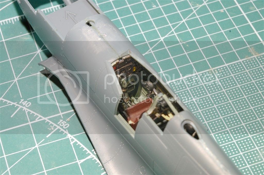
I finally finished the cockpit with the addition of the other cockpit tub wall.

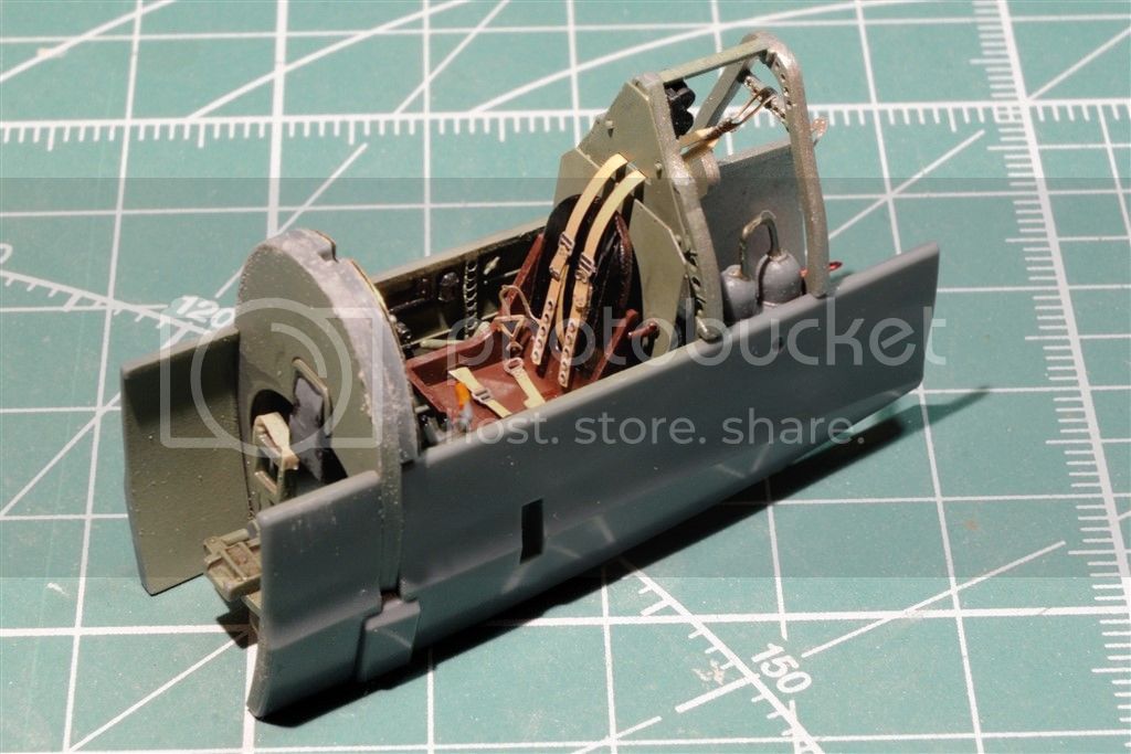
Test fitting showed that the IP needed to be sanded to allow the fuselage halves to mate perfectly.

Depending on which particular aircraft one is modeling, the front of the Fuselage wing faring is different. So Eduard has produced both versions. the seam is right along actual seams, so care must be taken when gluing them in place. I opted to glue them in from the rear with a very small amount of Tamiya Extra thin. This preserved the panel lines so no re-scribing nor sanding would be required.
Up next is the start of the lower wing assembly.
Joel
I finally finished the cockpit with the addition of the other cockpit tub wall.


Test fitting showed that the IP needed to be sanded to allow the fuselage halves to mate perfectly.

Depending on which particular aircraft one is modeling, the front of the Fuselage wing faring is different. So Eduard has produced both versions. the seam is right along actual seams, so care must be taken when gluing them in place. I opted to glue them in from the rear with a very small amount of Tamiya Extra thin. This preserved the panel lines so no re-scribing nor sanding would be required.

Up next is the start of the lower wing assembly.
Joel

surgeon01

Joined: February 20, 2005
KitMaker: 204 posts
AeroScale: 99 posts
Posted: Friday, March 27, 2015 - 03:32 AM UTC
Great progress Joel, the cockpit looks brilliant, what a nice busy inside. Btw. I found the PE's for the instrument panels quite often to large.
greetings ro
greetings ro

Joel_W
Joined: December 04, 2010
KitMaker: 11,666 posts
AeroScale: 7,410 posts
Posted: Friday, March 27, 2015 - 04:54 AM UTC
Quoted Text
Great progress Joel, the cockpit looks brilliant, what a nice busy inside. Btw. I found the PE's for the instrument panels quite often to large.
greetings ro
Robert,
In this case the two full size PE IPs PE1 & PE2 fit the plastic backing plate F66 like a glove. That sub assembly gets glued to the IP bulkhead F4. All those parts do indeed seem to be the same shape and size. The issue that I noted above was that the entire sub assembly was slightly too large to allow both fuselage halves to mate perfectly. Fortunately, a little sanding to decrease the overall dia. and both fuselage halves snugged right up.
Joel
SaxonTheShiba
Joined: February 01, 2009
KitMaker: 1,233 posts
AeroScale: 663 posts

Posted: Friday, March 27, 2015 - 07:13 AM UTC
Great looking interior Joel! Don't you love that Eduard interior detail? Use caution on the longitudinal cowling seam. For whatever reason, it's slightly persistent when you try to blend it. Looks awesome so far.
Best wishes,
Ian
Best wishes,
Ian
Joel_W
Joined: December 04, 2010
KitMaker: 11,666 posts
AeroScale: 7,410 posts
Posted: Friday, March 27, 2015 - 06:41 PM UTC
Quoted Text
Great looking interior Joel! Don't you love that Eduard interior detail? Use caution on the longitudinal cowling seam. For whatever reason, it's slightly persistent when you try to blend it. Looks awesome so far.
Best wishes,
Ian
Ian,
Thanks for appreciating theirs and my work. Believe me it's 90% them, and only 10% me.
I've heard that about the seam from reading several of their Spitfire builds. Sounds weird, but it must be true. My plan is to glue, sand, polish, then seal with Gorilla CA which falls right between thin and Gel. Wait 10 min, then sand, and polish. Hopes that takes care of the issue.
Joel
Joel_W
Joined: December 04, 2010
KitMaker: 11,666 posts
AeroScale: 7,410 posts
Posted: Monday, March 30, 2015 - 02:32 AM UTC
Well, with all the snow that just continues to cover Long Island even though it's spring, and being semi retired at work, I've been spending more time at the bench then normally. So I've made enough progress on the Spit. Mk.IXc for another update.
With the basic fuselage finished, I've sanded the main seams then coated them with Zap-A-Gap thin CA glue. Even though the fit was just about perfect, Extra Thin not only melts the plastic for a strong bond, but as it oozes out of the seam often I get bubbles that need filling. The thin CA glue does the trick and seals any seams I missed.
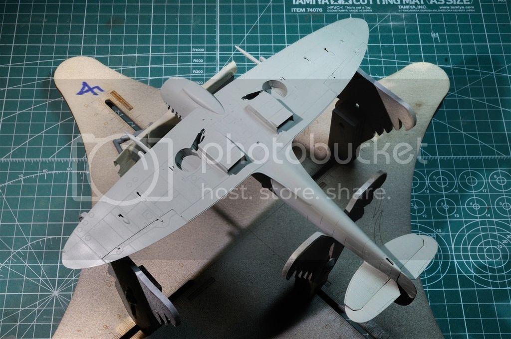
Next up is the wing assemblies. The lower wing section is a one piece unit that is extremely well detailed. Eduard designed the wheel wells with one common large wing spar and 7 smaller pieces that comprised each well. Critical alignment of each piece is necessary or the well just won't fit together properly. While the finished wheel wells have the correct oblong shape rather then the more traditional vertical walls, it's just over engineered, and very fiddly in construction. Half the amount of parts is all that would be needed to produce each well.
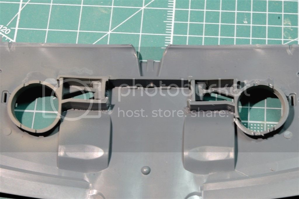
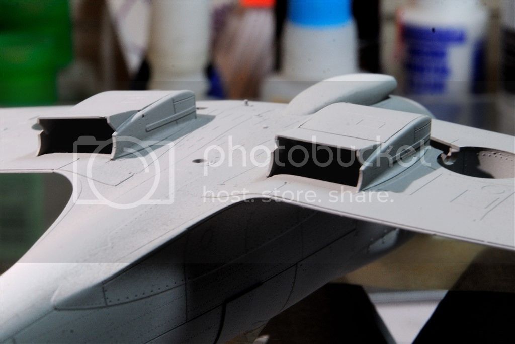
Next in the construction of the wings is the two cooling system radiators. And once again Eduard decided to see how many parts they can create to make each one. Assembling them required test fitting into the wing before the glue had really set to tweak the alignment. One nice touch is the rear radiator door can be displayed open or closed, and there are two different hinges for those options. I chose to have them open, but left them off till just before painting.
You can also see how nicely detailed the wheels wells look when viewed from the bottom.

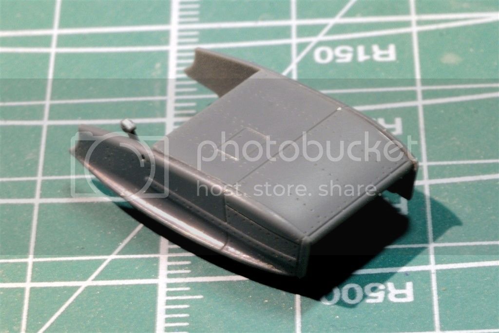
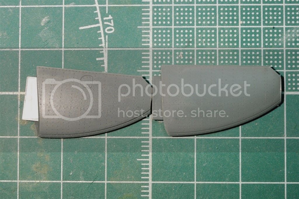
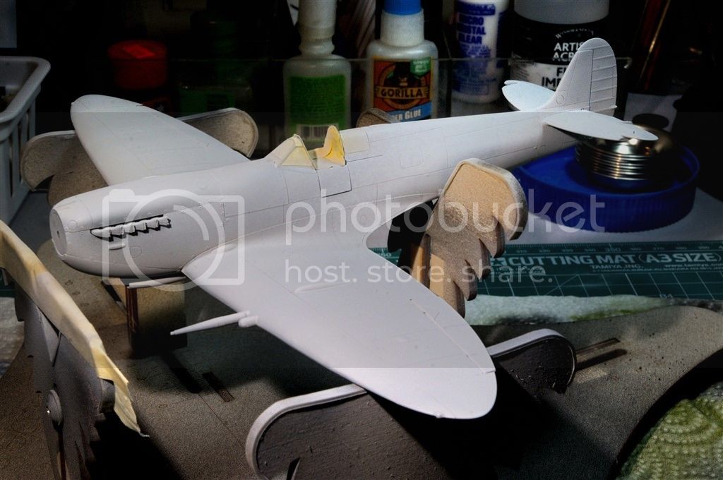
I also decided it was a good time to build the rear horizontal stabilizers. Eduard really did an excellent job with the engineering of these parts. Rather then the almost universal top and bottom halves that are sliced right through the stabilizers, the molded the bottom with the front lip, and created the joining seam where the actual seam is. The effect is absolutely perfect both visually and construction wise.
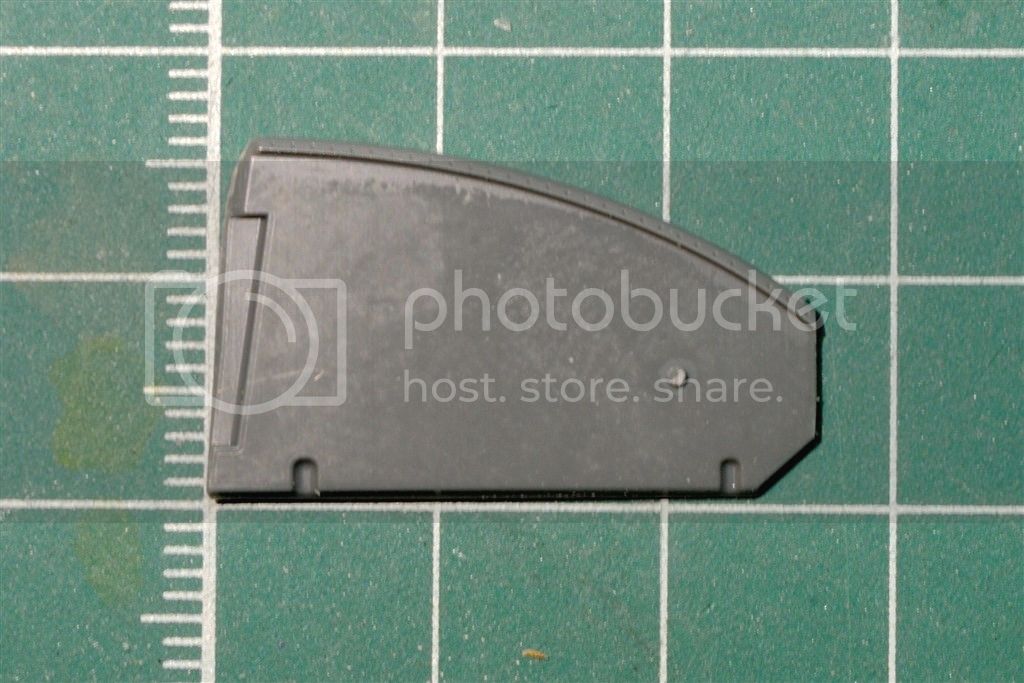
It's so good, try and see if you can tell the top from the bottom. The answer is at the end of the update.
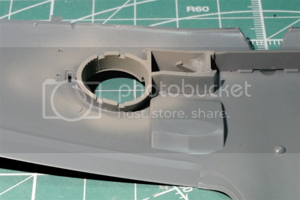
Before I could install the engine cowling, I had to build the two exhaust header manifolds. Once again Eduard decided to see how many pieces they could create for each sub assembly. Each one is comprised of 4 pcs.
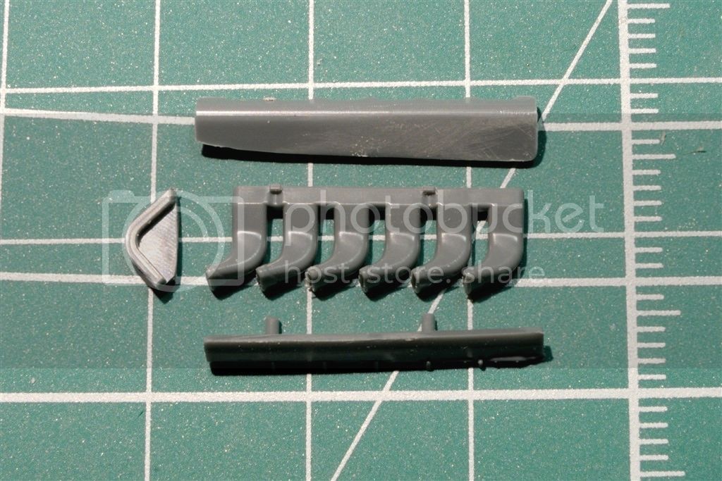
The instructions were extremely hard for me to visual the proper orientation of the parts, coupled with another fiddly sub-assembly, gets my vote for the worst part of the build. But with due diligence I got them done.
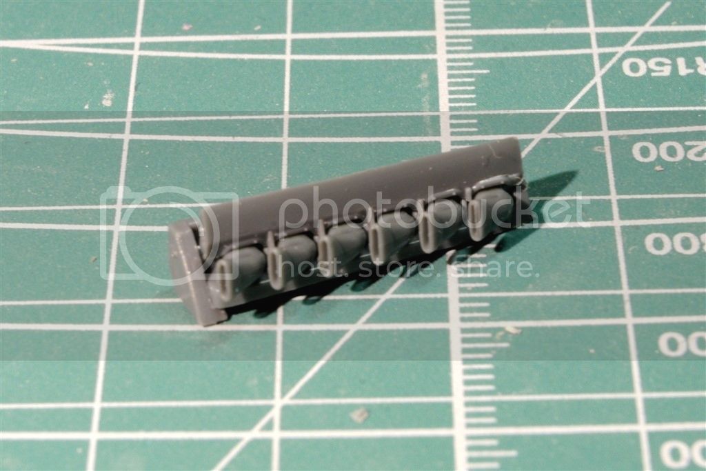
Once both are installed, only the header is visible, so a simpler assembly would have been greatly appreciated. I had previously glued and test fitted the engine cowling to make sure that I wouldn't have any surprises. I've also read and followed enough Eduard Spit builds to know that the cowling is a real problem with the center joint line. It seams for some reason that no matter how many times it was gone over with model putty, the seam just reappeared after priming or painting. So I did the CA glue routine again. And will prime and let it seat for a day just to be sure.

The Answer to the stabilizer question is the one on the left has the joint seam facing up. Looks pretty good if you ask me. I was going to add a pin wash to the other stabilizer, but figured that was pushing it a bit.
Joel
With the basic fuselage finished, I've sanded the main seams then coated them with Zap-A-Gap thin CA glue. Even though the fit was just about perfect, Extra Thin not only melts the plastic for a strong bond, but as it oozes out of the seam often I get bubbles that need filling. The thin CA glue does the trick and seals any seams I missed.
Next up is the wing assemblies. The lower wing section is a one piece unit that is extremely well detailed. Eduard designed the wheel wells with one common large wing spar and 7 smaller pieces that comprised each well. Critical alignment of each piece is necessary or the well just won't fit together properly. While the finished wheel wells have the correct oblong shape rather then the more traditional vertical walls, it's just over engineered, and very fiddly in construction. Half the amount of parts is all that would be needed to produce each well.


Next in the construction of the wings is the two cooling system radiators. And once again Eduard decided to see how many parts they can create to make each one. Assembling them required test fitting into the wing before the glue had really set to tweak the alignment. One nice touch is the rear radiator door can be displayed open or closed, and there are two different hinges for those options. I chose to have them open, but left them off till just before painting.

You can also see how nicely detailed the wheels wells look when viewed from the bottom.

I also decided it was a good time to build the rear horizontal stabilizers. Eduard really did an excellent job with the engineering of these parts. Rather then the almost universal top and bottom halves that are sliced right through the stabilizers, the molded the bottom with the front lip, and created the joining seam where the actual seam is. The effect is absolutely perfect both visually and construction wise.

It's so good, try and see if you can tell the top from the bottom. The answer is at the end of the update.

Before I could install the engine cowling, I had to build the two exhaust header manifolds. Once again Eduard decided to see how many pieces they could create for each sub assembly. Each one is comprised of 4 pcs.

The instructions were extremely hard for me to visual the proper orientation of the parts, coupled with another fiddly sub-assembly, gets my vote for the worst part of the build. But with due diligence I got them done.

Once both are installed, only the header is visible, so a simpler assembly would have been greatly appreciated. I had previously glued and test fitted the engine cowling to make sure that I wouldn't have any surprises. I've also read and followed enough Eduard Spit builds to know that the cowling is a real problem with the center joint line. It seams for some reason that no matter how many times it was gone over with model putty, the seam just reappeared after priming or painting. So I did the CA glue routine again. And will prime and let it seat for a day just to be sure.

The Answer to the stabilizer question is the one on the left has the joint seam facing up. Looks pretty good if you ask me. I was going to add a pin wash to the other stabilizer, but figured that was pushing it a bit.
Joel
litespeed
Joined: October 15, 2009
KitMaker: 1,976 posts
AeroScale: 1,789 posts
Posted: Monday, March 30, 2015 - 03:20 AM UTC
The tailplane and exhaust pipes look superb Joel. Eduard at their best.
tim
tim

EdgarBrooks

Joined: June 03, 2006
KitMaker: 397 posts
AeroScale: 384 posts
Posted: Monday, March 30, 2015 - 03:31 AM UTC
As always, in my role as resident spoilsport, can I point out that the radiator flaps would only normally be open when being worked on.
On late Mark Spitfires they were operated by a temperature-controlled switch, and only opened at a specific temperature, closing again as the speed (and coolant temperature) reduced.
On late Mark Spitfires they were operated by a temperature-controlled switch, and only opened at a specific temperature, closing again as the speed (and coolant temperature) reduced.
Joel_W
Joined: December 04, 2010
KitMaker: 11,666 posts
AeroScale: 7,410 posts
Posted: Monday, March 30, 2015 - 03:32 AM UTC
Quoted Text
The tailplane and exhaust pipes look superb Joel. Eduard at their best.
tim
Tim,
The tail stabilizers are the best I've ever seen. The exhausts headers are also about the finest molded plastic ones I've ever seen in 1/48 scale. It's the whole header assembly that you don't even see that wasn't necessary.
It's still one of the best kits I've ever built. #1 is still the GWH 1/48 scale F-15C. It's in a class by itself.
Joel
Joel_W
Joined: December 04, 2010
KitMaker: 11,666 posts
AeroScale: 7,410 posts
Posted: Monday, March 30, 2015 - 05:20 AM UTC
Quoted Text
As always, in my role as resident spoilsport, can I point out that the radiator flaps would only normally be open when being worked on.
On late Mark Spitfires they were operated by a temperature-controlled switch, and only opened at a specific temperature, closing again as the speed (and coolant temperature) reduced.
Edgar,
Darn. I just knew I should have posted and asked you about them. Not too sure I can correct as the hinges are glued into position and painted. To use the other hinges, I would need to use the other set of holes which would leave me with a nasty mess to clean up. Will sleep on it.
I was thinking at one point of dropping the flaps, but after doing some research I found out that they were always in the up position unless landing.
Joel
Joel_W
Joined: December 04, 2010
KitMaker: 11,666 posts
AeroScale: 7,410 posts
Posted: Monday, March 30, 2015 - 05:23 AM UTC
Edgar,
I do have a few questions.
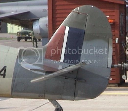
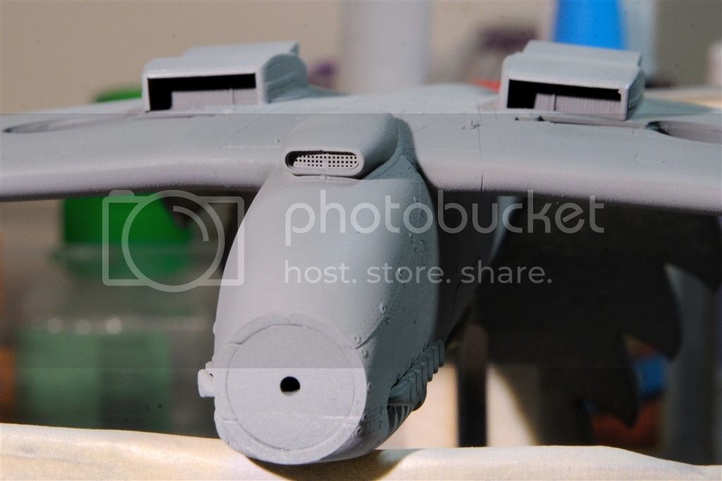
In the photo of the exhaust header installed, there is a bulge right below it. Is that a cartridge starter? Here's a picture of the real deal:

I've also been looking at the vertical and horizontal stabilizers in the kit. The fabric representation seems way over done compared to my references. Unfortunately, all my reference photos are of restorations at this point, so I can't be sure if the kit is over done or the restorations aren't done as they originally were.
Joel
I do have a few questions.
In the photo of the exhaust header installed, there is a bulge right below it. Is that a cartridge starter? Here's a picture of the real deal:

I've also been looking at the vertical and horizontal stabilizers in the kit. The fabric representation seems way over done compared to my references. Unfortunately, all my reference photos are of restorations at this point, so I can't be sure if the kit is over done or the restorations aren't done as they originally were.

Joel
EdgarBrooks
Joined: June 03, 2006
KitMaker: 397 posts
AeroScale: 384 posts
Posted: Monday, March 30, 2015 - 01:08 PM UTC
The "bulge" is actually a scoop, to take cooling air into, round, and back out of the electric generator.
Cartridge starters were always on the starboard side of the engine, with the drive going forward into the (extended sideways - hence the small teardrop bulge on the Spitfire II) gearbox just behind the propeller.
That extension also worked the other way, driving an air compressor to supply air to the pressurised cockpit of the VII; there was a surplus of those engines, so some were fitted into the VIII & IX, which is why you sometimes see that teardrop bulge on their cowlings.
I don't know, for sure, if the attaching of fabric is always done in exactly the same way as it was in the war, but I'm doubtful. I have a handwritten note on how it was done, including the number of stitches per inch, fabric spec., etc., and though I know that there are some restorers who are proud to do it the same way, that doesn't apply to all.
The little bulges, that you sometimes see, are not the stitches, but knots, since the thread has to be knotted at regular intervals, to stop it unravelling, if it gets cut.
As an example, I know of one rebuilder, who always paints 20 coats of red dope on his rudders and elevators (not stabilisers, please,) while the wartime system was five coats, two of which were thinned 50:50 with thinners; there was also abandonment of the silver coat before camouflage was added.*
In "normal" times, the life of doped fabric was 5 years, but, in wartime, aircraft weren't expected to last that long, aluminium was wanted for far more important components, so why waste it in paint?
* This did not apply to the all-fabric Mosquito covering which did have silver dope over the red.

FredrikA
Joined: January 09, 2008
KitMaker: 92 posts
AeroScale: 90 posts
Posted: Monday, March 30, 2015 - 09:34 PM UTC
Great work continues, I see. I can understand your amazement with the fit. It is spectacular! I suppose that we will have to 'suffer' things like nine pieces of wheel well and those exhaust bits, in order to get that fit. Small price to pay?!
Anyway, I'm sure that your meticulousness with the joints will pay off. It's so annoying when the show up under the first coat of paint.
Looking forward to seeing more from you!
/Fredrik
Anyway, I'm sure that your meticulousness with the joints will pay off. It's so annoying when the show up under the first coat of paint.
Looking forward to seeing more from you!
/Fredrik
Joel_W
Joined: December 04, 2010
KitMaker: 11,666 posts
AeroScale: 7,410 posts
Posted: Tuesday, March 31, 2015 - 02:21 AM UTC
Edgar,
Thanks for that explanation. I now know what all those little bumps are from.
I'm going to sand down all the rear flying surfaces to better emulate the above picture. Since that picture is a restoration, the colors are the same. I'm going to lightly fade the colors to further emphasize the differences between metal and fabric surfaces.
And thank you for the information on that Bulge which is in reality a two sided vent. I literally had no idea of what it was.
Joel
Joel_W
Joined: December 04, 2010
KitMaker: 11,666 posts
AeroScale: 7,410 posts
Posted: Tuesday, March 31, 2015 - 02:24 AM UTC
Quoted Text
Great work continues, I see. I can understand your amazement with the fit. It is spectacular! I suppose that we will have to 'suffer' things like nine pieces of wheel well and those exhaust bits, in order to get that fit. Small price to pay?!
Anyway, I'm sure that your meticulousness with the joints will pay off. It's so annoying when the show up under the first coat of paint.
Looking forward to seeing more from you!
/Fredrik
Fredrik,
The wells are close, but not perfect. One of the reasons that I airbrushed the wells now was to see how they would look.
Joel
Joel_W
Joined: December 04, 2010
KitMaker: 11,666 posts
AeroScale: 7,410 posts
Posted: Friday, April 03, 2015 - 03:43 AM UTC
Time for another mini update.
The With the fuselage glued up, I just sanded and polished the seams. CA extra thin glue was used on the engine cowling seam as build after build stated that the seam with or without putty kept on reappearing after primer and paint. Hopefully, this will solve that issue.
Next was gluing up the wing assembly. It needed a little finesse sanding so it fit like a glove without having to pinch the fuselage halves. Both radiator housings were built and glued to the lower wings. I opted to have the vent doors in the open position before Edgar posted that they should be in the closed position.
Last but not least was the chin oil cooler which has a PE screen installed. The oil cooler seam also required some Putty work with Bondo, then sealed with CA glue.
Up next was the installation of the rear vertical and horizontal stabilizers. Followed by the Rudder, Elevators, and the Ailerons.
I let the glue cure for a few days, then today I primed with Tamiya Lacquer base primer sealer. This was the 1st time I had used my new Iwata Eclipse with lacquer primer, and I wasn't really happy with the results. The .35mm needle and cone just doesn't put out enough paint, so I ended up with a rough textured surface that literally was covered with dry powder. It was easy enough to remove with just a soft cotton rag and a large paint brush. So for priming and clear coats where I want to apply a wet coat, I'm going to go back to my Paasche H airbrush with the 5 setup.

I let the primer dry for a few hours, then I air brushed the bottom of Spitfire with Tamiya's new XF-83 Medium Sea Gray acrylic paint. It's quite a bit darker then their old stand by XF-20 Medium Gray that I had originally air brushed the wheel wells with.
Joel
The With the fuselage glued up, I just sanded and polished the seams. CA extra thin glue was used on the engine cowling seam as build after build stated that the seam with or without putty kept on reappearing after primer and paint. Hopefully, this will solve that issue.
Next was gluing up the wing assembly. It needed a little finesse sanding so it fit like a glove without having to pinch the fuselage halves. Both radiator housings were built and glued to the lower wings. I opted to have the vent doors in the open position before Edgar posted that they should be in the closed position.

Last but not least was the chin oil cooler which has a PE screen installed. The oil cooler seam also required some Putty work with Bondo, then sealed with CA glue.

Up next was the installation of the rear vertical and horizontal stabilizers. Followed by the Rudder, Elevators, and the Ailerons.
I let the glue cure for a few days, then today I primed with Tamiya Lacquer base primer sealer. This was the 1st time I had used my new Iwata Eclipse with lacquer primer, and I wasn't really happy with the results. The .35mm needle and cone just doesn't put out enough paint, so I ended up with a rough textured surface that literally was covered with dry powder. It was easy enough to remove with just a soft cotton rag and a large paint brush. So for priming and clear coats where I want to apply a wet coat, I'm going to go back to my Paasche H airbrush with the 5 setup.


I let the primer dry for a few hours, then I air brushed the bottom of Spitfire with Tamiya's new XF-83 Medium Sea Gray acrylic paint. It's quite a bit darker then their old stand by XF-20 Medium Gray that I had originally air brushed the wheel wells with.

Joel
Holdfast
#056
Joined: September 30, 2002
KitMaker: 8,581 posts
AeroScale: 4,913 posts
Posted: Saturday, April 04, 2015 - 12:55 PM UTC
Quoted Text
Last but not least was the chin oil cooler which has a PE screen installed.
Hi Joel, I believe that is the carburettor air intake, the oil coolers are alongside the radiators, the smaller section to inboard
 |

WEB HOSTING BY


Copyright ©2021 AeroScale and Kitmaker Network, a subsidiary of Silver Star Enterprises
All Rights Reserved. Please read our Conditions of Use and Privacy Policy.
All Rights Reserved. Please read our Conditions of Use and Privacy Policy.