Steffen, Jean-Luc, Mal- Thanks so much! An article from me? I'll take that as a real compliment...

Brian- I'm nutty all right- thanks!

Carl- I built scale free-flight rubber power back when I lived on the East Coast, in North Carolina. We flew our ships on a hundred-acre sod farm! Here in LA, it's windy and covered in houses, so it's styrene for me now.
Merlin-

to you, too!
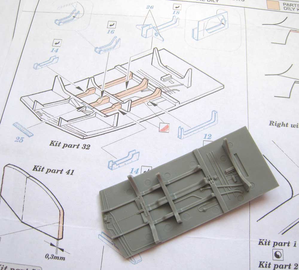
So, here goes- I cut away the bulkhead, thinned the sides (sooooooo boring!), filled the ejector pin marks, thinned the sides some more and cut away the access panels. Not all -4's had the upper panel, but I figured screw it! I want this work to be seen. Next came the fun stuff- building up the inner ribbing. Aaaah- modeling heaven!

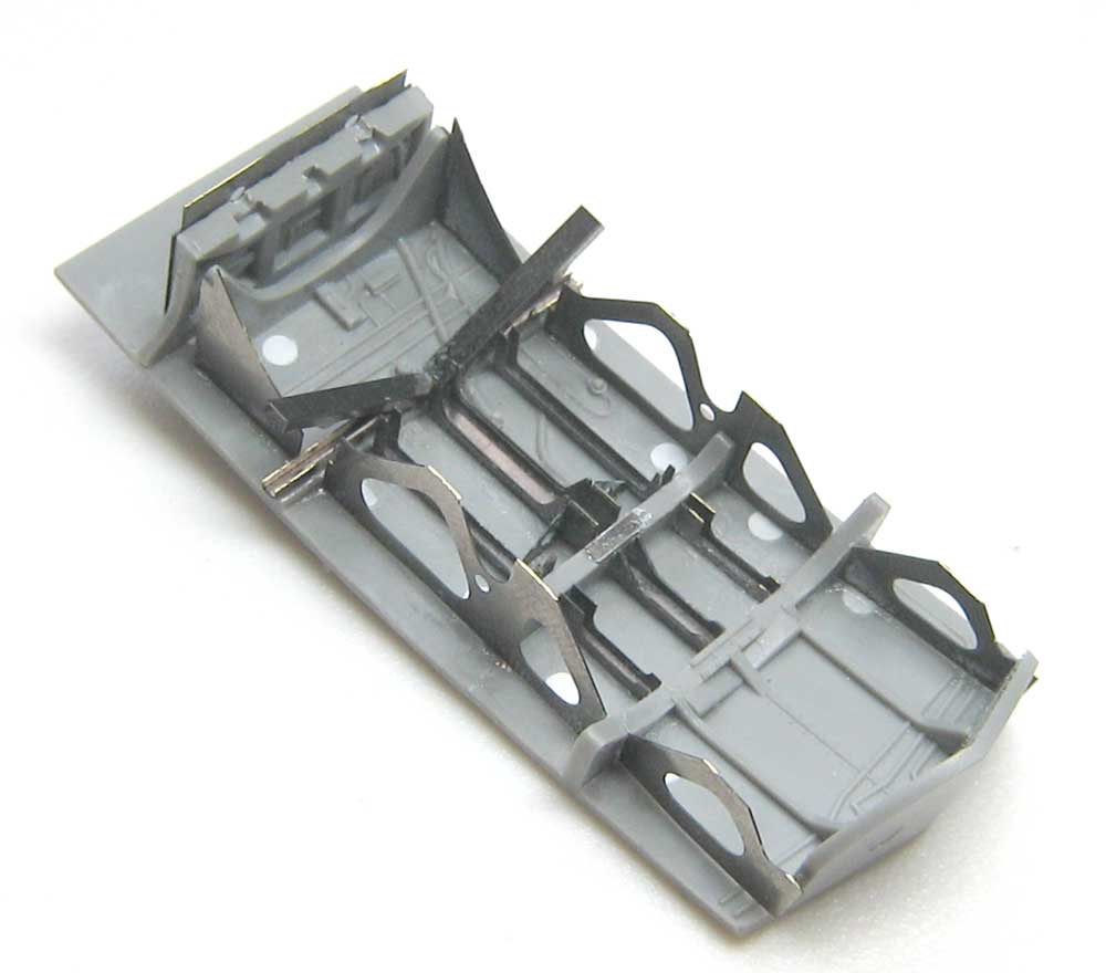
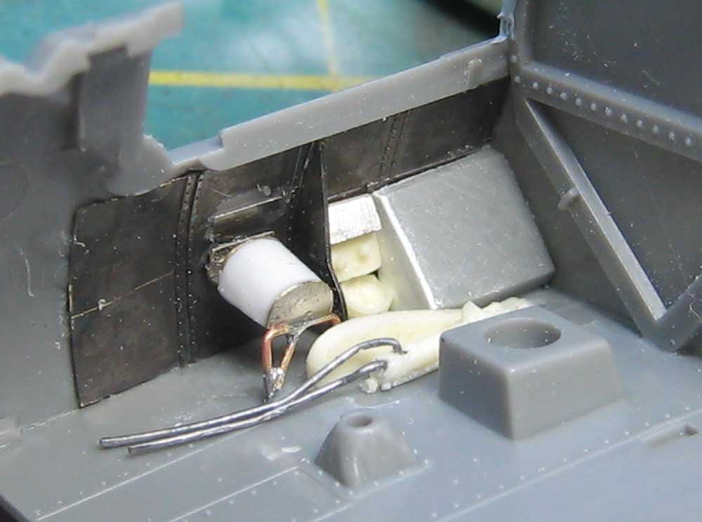
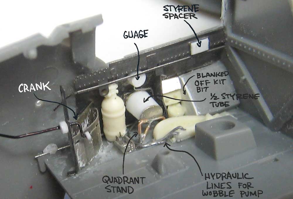
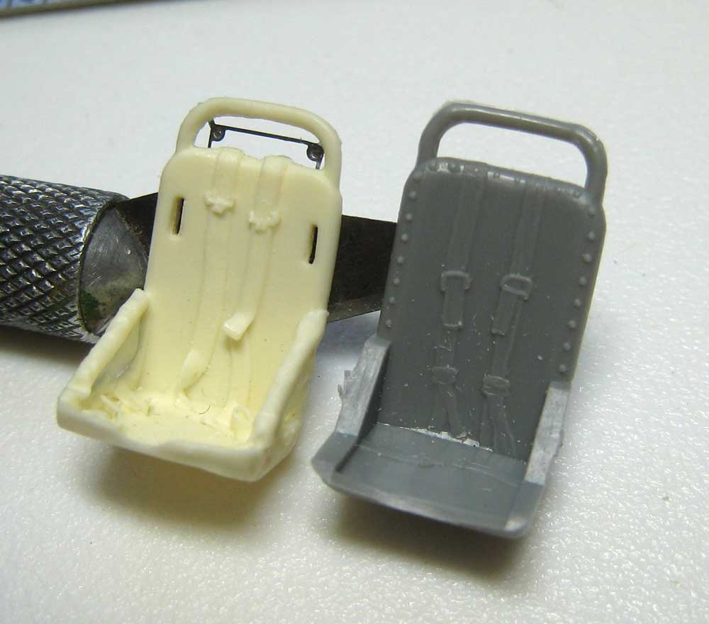
I began building from the front of the compartment- here are the two front legs of the turnover pylon and the pilot's armor panel. Details from bits of strip stock and sliced sprue, just like our armor-building brethren. See the notes for various details- and pitfalls!

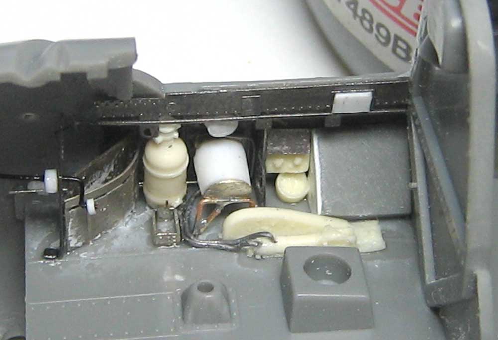
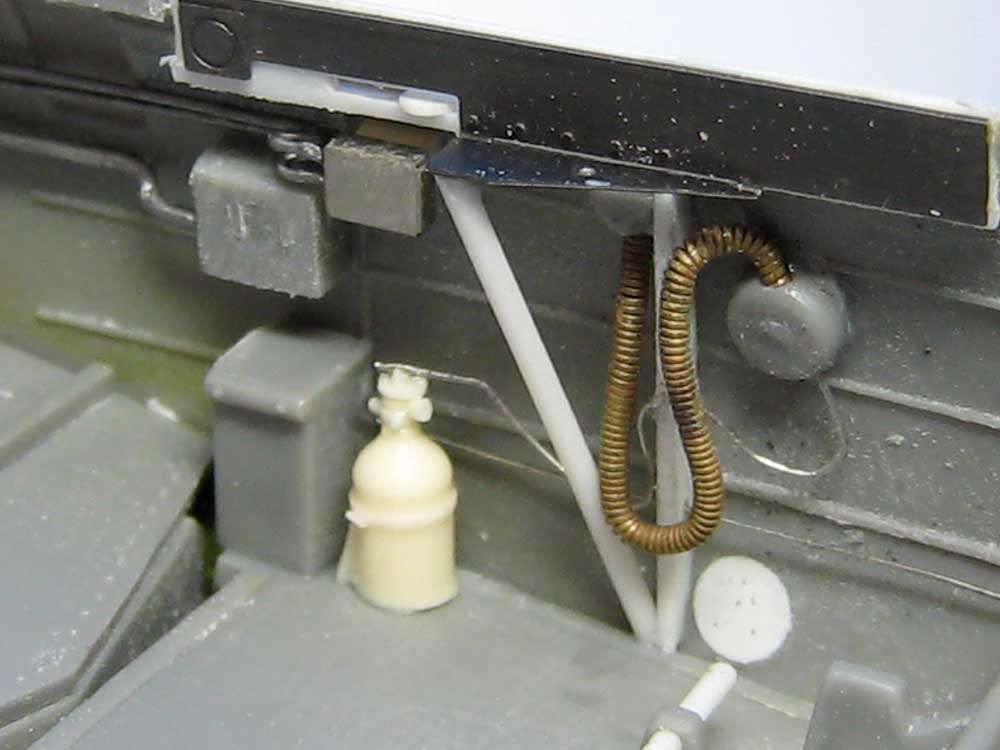
The ribbing on the other side was a bit more challenging with the various subcomponents already in place. Not crushing things is always priority one! I glued the front assembly in and added one of the rear braces. Note that I've gotten those rivets installed correctly at last.

The fourth leg was carefully added- I did some test-fitting with the other fuselage half in place before gluing.
The radio is set in place temporarily to assess the size of the pylons. I'm doing this by the Mk I Eyeball method.

I did some caliper measurements on the space between the pylon legs, drew up some paper patterns and cut the endcaps of the tank from styrene. These in turn were glues to a small block of balsa wood. The tank is, lengthwise, flat along the top but sloped on the bottom, so these endcaps are differently-sized.

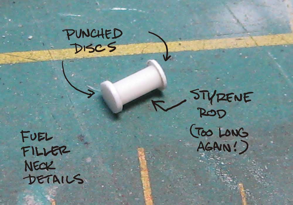
With a sanding block I carved the tank to shape- it was pretty easy, as the endcaps set the shape. I got the to and bottom angles right, but the tank was too long. Well, it's easier to take material away than add it...


Using my trusty calipers I scribed a line around the rear end of the tank, held my breath and cut it off. Success! From here it was a simple trick to glue it a scrap of styrene and trim that down to match the balsa profile. Whew!

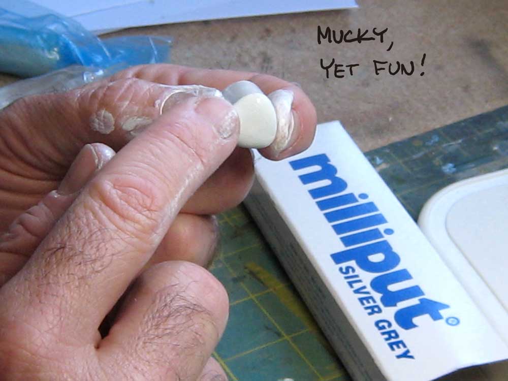
I wrapped a bit of paper around the tank to create a rough pattern, then used it to cut a piece from .010 styrene. Wrapped, glued and trimmed to shape, it's starting to look like a fuel tank! There's more shaping to be done- I'll break out the Miliput for that. This photo shows how much more internal ribbing needs to be added- not much, but that's for later! ;D