
Hosted by Rowan Baylis
Airfix 1/24 Scale Hawker Typhoon Build.
Gremlin56
Joined: October 30, 2005
KitMaker: 3,897 posts
AeroScale: 564 posts
KitMaker: 3,897 posts
AeroScale: 564 posts

Posted: Tuesday, July 29, 2014 - 03:58 PM UTC
Oops, my mistake, yes, it was a Hessian mercenary. Its been a couple of years since I saw the film 


the1pendragon

Joined: January 07, 2014
KitMaker: 25 posts
AeroScale: 25 posts

Posted: Wednesday, July 30, 2014 - 12:14 AM UTC
But I see your "headless horseman" did upgrade his horse to a much more powerful mount!! 
 Icabod Crane doesn't stand a snowballs chance in hell now!

 Icabod Crane doesn't stand a snowballs chance in hell now!
Scrodes

Joined: July 22, 2012
KitMaker: 771 posts
AeroScale: 763 posts

Posted: Wednesday, July 30, 2014 - 05:38 AM UTC
Quoted Text
Quoted TextEdit - I figured it would be easy figuring out the size of the squares by comparing them to the serial number which is a standard size.
Yes they are about 4" but like I said they are not square
I just realized that one of the markings in the kit has this blue and white checkerboard, so that solves all of our sizing problems. I'll still need the rest of the markings and if you can use the decal to make a mask that would be awesome.
Absolutely no rush, I'm still working away daily on Glenn's Mosquito.
Posted: Wednesday, July 30, 2014 - 05:48 PM UTC
Quoted Text
I just realized that one of the markings in the kit has this blue and white checkerboard, so that solves all of our sizing problems. I'll still need the rest of the markings and if you can use the decal to make a mask that would be awesome.
Well not completely as a decal performs differently to masking material and the decal is in four parts, so they likely overlap. However they are a start.

Posted: Thursday, August 14, 2014 - 05:40 PM UTC
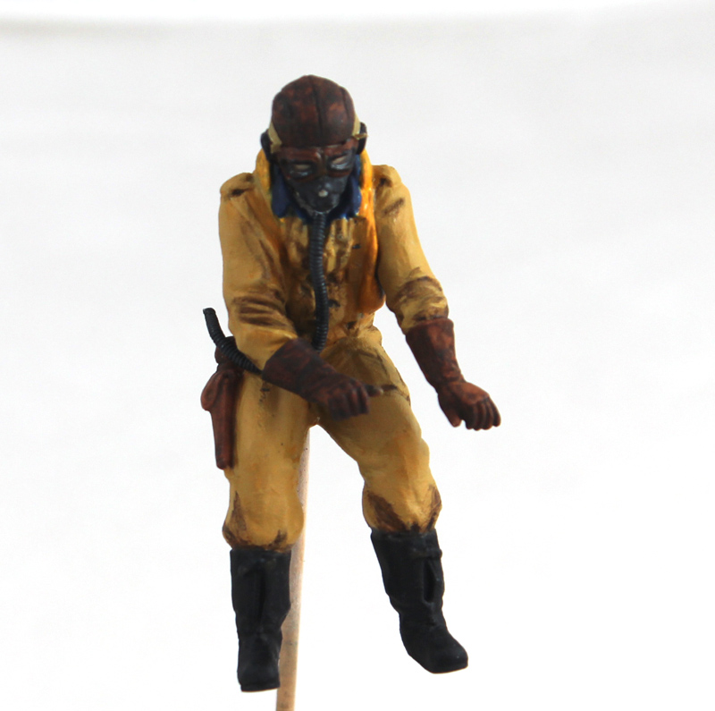
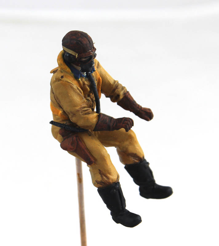
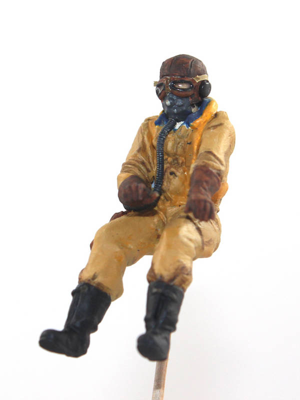
I have been working on getting the pilot figure painted after fairly successfully getting the goggles from the second pilot figure to fit. They are not perfect but they look OK? The really traumatic part was when I had to remove the goggles from the pilots helmet, as once that was started there was no going back. I ended up cutting the spare goggles in half and filing away the remnants of the nose piece to get them to better fit the face. They were painted and glued in place using PVA. The lenses were created with "Bare Metal Foil" glue, as it it dries totally clear.
I would never claim that the painting of the figure is very good but, under the closed canopy, he will look the part; I hope I created the oxygen hose from a length of thick wire wound with thin wire.
I have fitted the electric motor into the kits engine and fed the wires through the engine fire wall. There is a problem with the nylon connection shaft in that the hole through it isn't central! I have come up with a possible solution using a length of stainless steel tube which I can fix to the motor spindle and the plan is to fit the kit prop shaft to it. However I foresee a problem with this a approach; The friction that will be caused between the plastic parts could end up welding them together! I could grease the parts, but what grease do I use and will I need to replenish it. Oil might work, it should work but I figure that would definitely need to be replenished. That would mean leaving the kit engine cover off (no problem) and being able to remove the upper cowling panel. Doing so would mean providing it with a means to keep it from falling off during the operation of the motor! A pair of earth magnets would probably do the job. Another answer would be to provide an oiling pipe; but then there would be no way of seeing whats happening at the motor and there is the very great chance that too much oil would be applied! Anyway all this has to be solved if this is to work so I will be working on this over the next couple of weeks.
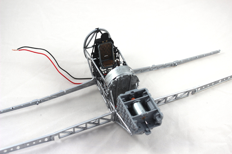
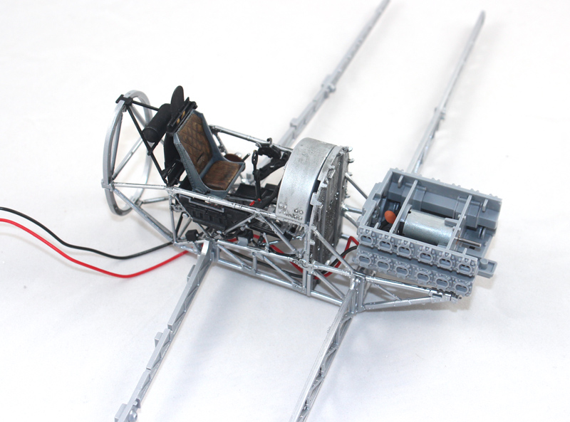
I haven't finished applying the instrument decals to the panel so I must get on with that as when that is done and the pilot figure is in place that will be the cockpit complete
I would never claim that the painting of the figure is very good but, under the closed canopy, he will look the part; I hope
 I created the oxygen hose from a length of thick wire wound with thin wire.


I have fitted the electric motor into the kits engine and fed the wires through the engine fire wall. There is a problem with the nylon connection shaft in that the hole through it isn't central! I have come up with a possible solution using a length of stainless steel tube which I can fix to the motor spindle and the plan is to fit the kit prop shaft to it. However I foresee a problem with this a approach; The friction that will be caused between the plastic parts could end up welding them together! I could grease the parts, but what grease do I use and will I need to replenish it. Oil might work, it should work but I figure that would definitely need to be replenished. That would mean leaving the kit engine cover off (no problem) and being able to remove the upper cowling panel. Doing so would mean providing it with a means to keep it from falling off during the operation of the motor! A pair of earth magnets would probably do the job. Another answer would be to provide an oiling pipe; but then there would be no way of seeing whats happening at the motor and there is the very great chance that too much oil would be applied! Anyway all this has to be solved if this is to work so I will be working on this over the next couple of weeks.


I haven't finished applying the instrument decals to the panel so I must get on with that as when that is done and the pilot figure is in place that will be the cockpit complete

Gremlin56
Joined: October 30, 2005
KitMaker: 3,897 posts
AeroScale: 564 posts
KitMaker: 3,897 posts
AeroScale: 564 posts

Posted: Thursday, August 14, 2014 - 05:59 PM UTC
Nice work on the pilot Mal, he will look great fitted in the cockpit. You did a great job cleaning up the flying helmet after removing the goggles too.


Biggles87

Joined: August 15, 2011
KitMaker: 57 posts
AeroScale: 55 posts

Posted: Friday, August 15, 2014 - 02:56 AM UTC
Ditto 


Joel_W

Joined: December 04, 2010
KitMaker: 11,666 posts
AeroScale: 7,410 posts

Posted: Friday, August 15, 2014 - 12:47 PM UTC
Mal,
Your pilot is really coming along quite well.
Not so sure I can see the reason for a spinning prop is such a finely detailed display model, but that's just me.
Joel
Your pilot is really coming along quite well.
Not so sure I can see the reason for a spinning prop is such a finely detailed display model, but that's just me.
Joel
Posted: Friday, August 15, 2014 - 06:25 PM UTC
Quoted Text
Not so sure I can see the reason for a spinning prop is such a finely detailed display model, but that's just me.
Joel
Well as I need to get this built before the IPMS (UK)Scale Modelworld show in November, I don't have the time to build it on its wheels, so it will be in flight. If its in flight it really needs to have the prop spinning. The idea is that it brings punters to my trade stand where they will find out about the masking and painting demos that I will be doing and the Typhoon mask set that I will be selling.
Joel_W

Joined: December 04, 2010
KitMaker: 11,666 posts
AeroScale: 7,410 posts

Posted: Saturday, August 16, 2014 - 10:05 AM UTC
Mal,
Thanks for the explanation. It does make perfect sense.
Joel
Thanks for the explanation. It does make perfect sense.
Joel
Posted: Sunday, August 17, 2014 - 08:21 PM UTC
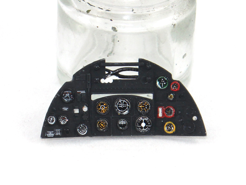
I have finished the instrument panel; I used the kit decals which aren't bad.
I also think that I have solved the problems of the spinning prop, more on that when it is done and I can post the pics.
Joel_W

Joined: December 04, 2010
KitMaker: 11,666 posts
AeroScale: 7,410 posts

Posted: Monday, August 18, 2014 - 02:08 AM UTC
Mal,
Outstanding IP.
Joel
Outstanding IP.
Joel
Gremlin56
Joined: October 30, 2005
KitMaker: 3,897 posts
AeroScale: 564 posts
KitMaker: 3,897 posts
AeroScale: 564 posts

Posted: Monday, August 18, 2014 - 05:24 AM UTC
Looks really good Mal, very neat.


Posted: Monday, August 18, 2014 - 06:12 PM UTC
Thanks Guys, it actually looks better in real life, the instruments are glazed with Klear, which isn't showing up in the picture, the same for the bezels which are semi gloss black. This makes them stand out more realistically than dry brushing. 
The spinning prop mechanism has progressed a little, I needed to drill out the kit prop spindle at around 2.1mm and of course buying a drill that size would have been expensive! I will try and post some pics by the end of the week but I have my Gran daughter staying so much of my time is taken up at the moment

The spinning prop mechanism has progressed a little, I needed to drill out the kit prop spindle at around 2.1mm and of course buying a drill that size would have been expensive! I will try and post some pics by the end of the week but I have my Gran daughter staying so much of my time is taken up at the moment

Posted: Tuesday, August 19, 2014 - 03:42 AM UTC
Looks pukka Mal!
Steve
Steve
chukw1

Joined: November 28, 2007
KitMaker: 817 posts
AeroScale: 729 posts

Posted: Tuesday, August 19, 2014 - 04:35 AM UTC

Scrodes

Joined: July 22, 2012
KitMaker: 771 posts
AeroScale: 763 posts

Posted: Tuesday, August 19, 2014 - 04:51 AM UTC
Posted: Tuesday, August 19, 2014 - 07:08 PM UTC
Yes Chuck they are masks 


Removed by original poster on 08/27/14 - 07:32:00 (GMT).
Posted: Tuesday, August 26, 2014 - 08:30 PM UTC
I have had to work out how to get a connection from the motor to the prop as the hole in the nylon connector that came with the motor is off centre. After lots of head scratching I decided that I would utilise the kit parts. I could see inherent problems with this but I think that I have managed to over come them.
I used a length of stainless steel tube to connect to the motor spindle. I cut the pin of the stop, drilled it out so that it fitted snugly over the tube. I drilled out the kit prop spindle to take the stainless tube.
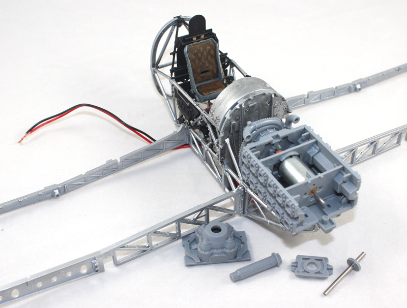
The tube goes through the holder and connects through the kit spindle and is held securely with epoxy.
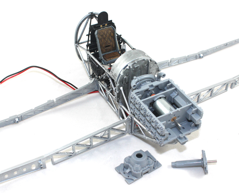
The kit spindle fits through the front gearbox(?) and this fits to the front of the engine.
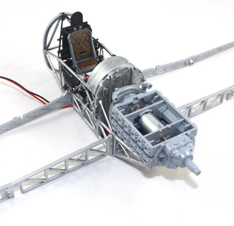
These pictures show the trial fitting so the scary bits are yet to happen, wish me luck
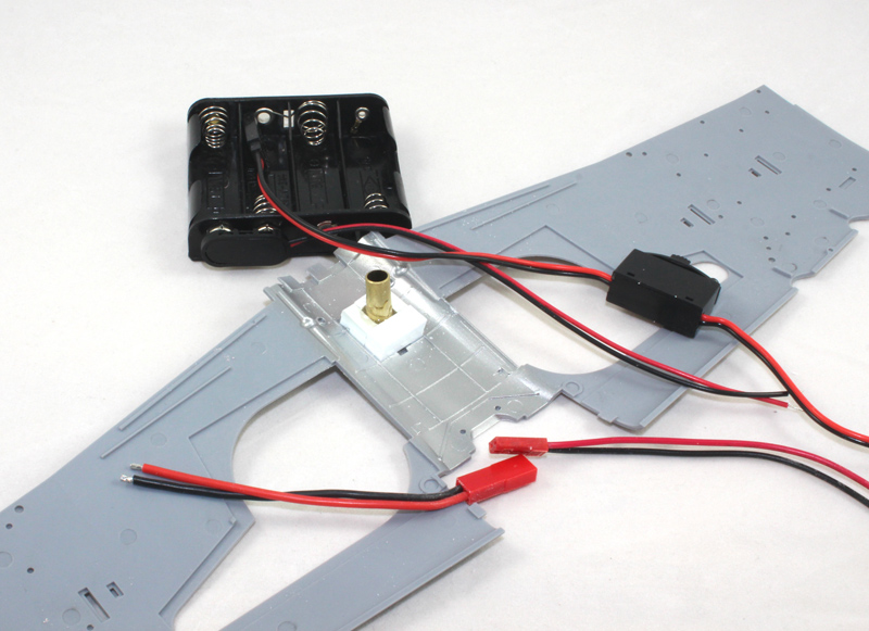
To be able to have the motor spin the prop there needs to be an electrical connection. The weighty model also need to be held aloft. The Airfix stand is a bit low so I have decided to hold it up using brass tube. So I have fitted a 1/4" brass tube in to the lower wing and to halp support the weight I have added styrene strip support, all epoxied in place. I cut the tube with a tube cutter which conveniently burs the end over preventing the tube that will slide into it from passing through. The problem is how to get the connector down the tube as it is a little too large! I think that I have the solution, so more on that in the next installment.
Yes this does fit below the cockpit gubbins, without fouling anything, just
I used a length of stainless steel tube to connect to the motor spindle. I cut the pin of the stop, drilled it out so that it fitted snugly over the tube. I drilled out the kit prop spindle to take the stainless tube.

The tube goes through the holder and connects through the kit spindle and is held securely with epoxy.

The kit spindle fits through the front gearbox(?) and this fits to the front of the engine.

These pictures show the trial fitting so the scary bits are yet to happen, wish me luck

To be able to have the motor spin the prop there needs to be an electrical connection. The weighty model also need to be held aloft. The Airfix stand is a bit low so I have decided to hold it up using brass tube. So I have fitted a 1/4" brass tube in to the lower wing and to halp support the weight I have added styrene strip support, all epoxied in place. I cut the tube with a tube cutter which conveniently burs the end over preventing the tube that will slide into it from passing through. The problem is how to get the connector down the tube as it is a little too large! I think that I have the solution, so more on that in the next installment.

Yes this does fit below the cockpit gubbins, without fouling anything, just

Joel_W

Joined: December 04, 2010
KitMaker: 11,666 posts
AeroScale: 7,410 posts

Posted: Wednesday, August 27, 2014 - 03:08 AM UTC
Mal,
Looking quite good. The tubing and supports should work out well.
Joel
Looking quite good. The tubing and supports should work out well.
Joel

Scrodes

Joined: July 22, 2012
KitMaker: 771 posts
AeroScale: 763 posts

Posted: Wednesday, August 27, 2014 - 03:50 AM UTC
I'm curious. Since Airfix went to the trouble to engineer the kit so you can build it wheels up and have provided an optional electric motor - were they as thoughtful as Tamiya - did they provide a stand?
edit - I am read good.
edit - I am read good.
Posted: Wednesday, August 27, 2014 - 07:24 PM UTC
Quoted Text
I'm curious. Since Airfix went to the trouble to engineer the kit so you can build it wheels up and have provided an optional electric motor - were they as thoughtful as Tamiya - did they provide a stand?
Yes Matt they do, but it isn't suitable for what I plan on doing.
The motor is connected via epoxy. I modified a syringe so that I could inject it into the stainless tube otherwise I wouldn't have been able to get sufficient in there to make the best and foolproof of connections. The motor happily turns the spindle but, even though I positioned the gear box will the epoxy set, the shaft won't turn with it in position! I think that I know what the problem is so I have to now work out a way to allow it to turn freely! I have also fitted the radiator and the ducting.
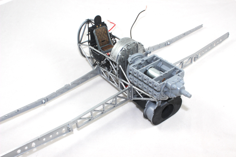
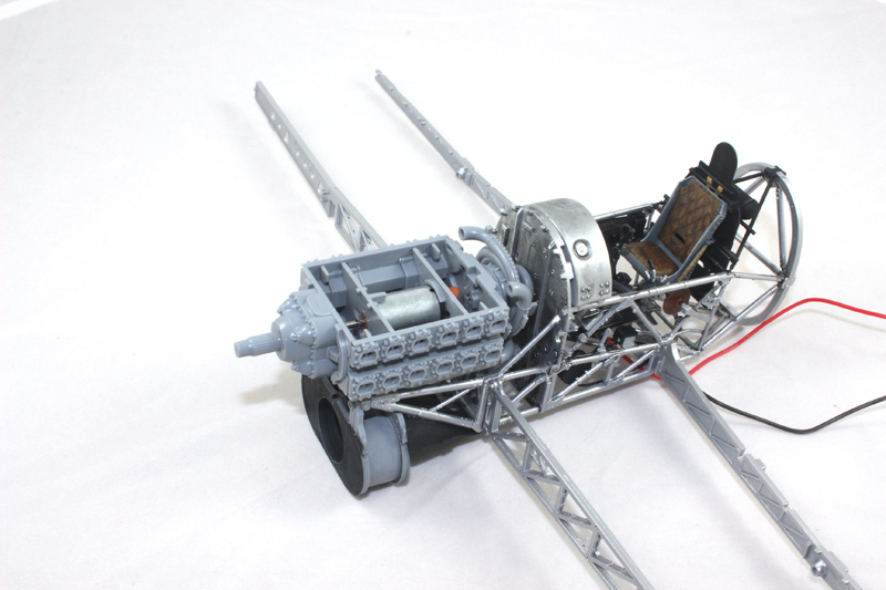
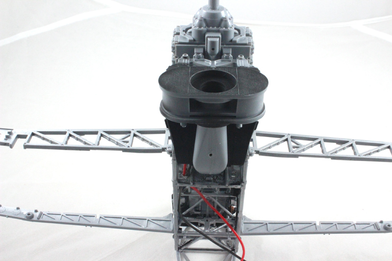
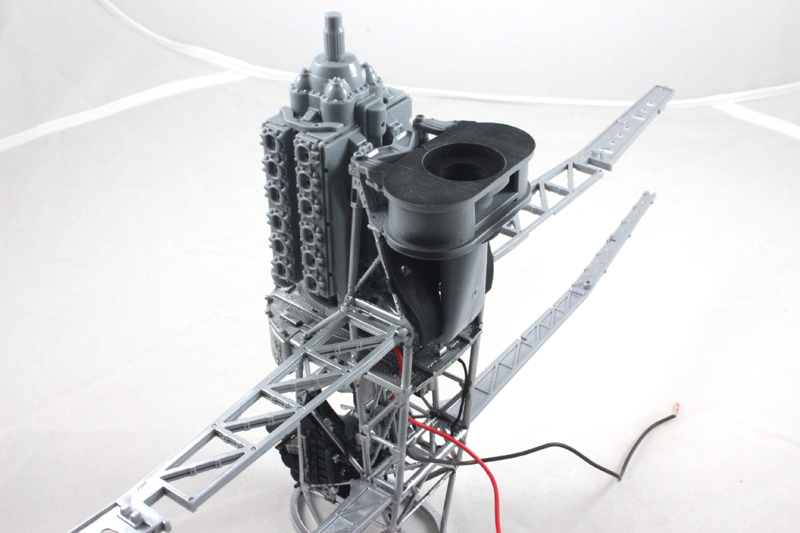
I have used vasaline as a lubricant in the gearbox, that might prove a problem when I come to finally glue the gearbox on, but that should be easy(ish) to solve; but I want to make sure that any friction on the plastic parts doesn't cause them to weld themselves together!

I can't fit the pilot figure or the instrument panel until I solve the problem with the prop shaft spinning as I am likely to do them some damage with the necessary handling but I might be able to get the wings on

berndm

Joined: March 26, 2014
KitMaker: 844 posts
AeroScale: 630 posts

Posted: Thursday, August 28, 2014 - 12:48 AM UTC
Hi Mal, your Typhoon with the turning prop will look awesome
on your display.Congratulations for the pilot !
Bernd
on your display.Congratulations for the pilot !
Bernd
Gremlin56
Joined: October 30, 2005
KitMaker: 3,897 posts
AeroScale: 564 posts
KitMaker: 3,897 posts
AeroScale: 564 posts

Posted: Thursday, August 28, 2014 - 02:23 AM UTC
That is a big operation you have underway Mal, but it should look very sexy with the prop spinning and the rockets leaving their rails.


 |


