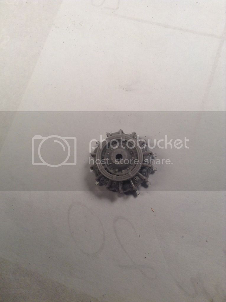
I've been inching forward with the oil cooler. This is a very prominent
" in-your-face" feature in the cowl opening and so I wanted to try and improve upon the molded plastic kit part.
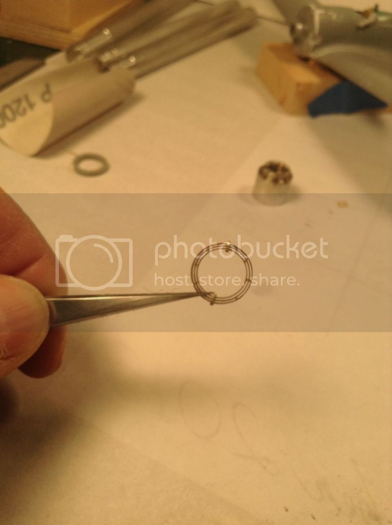
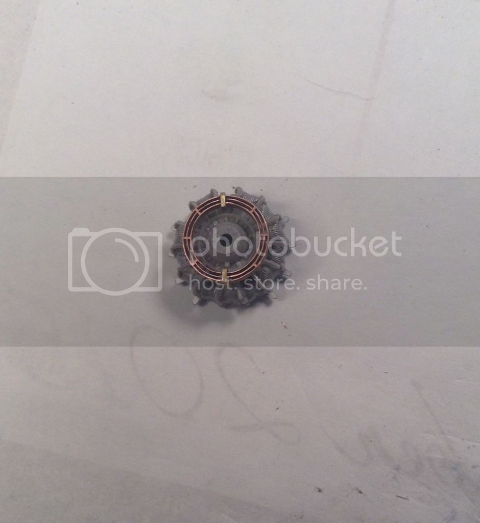
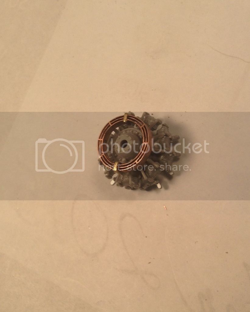
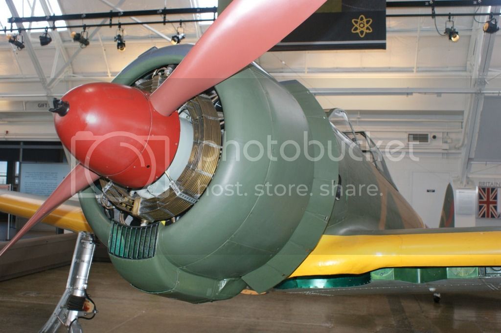
Here is what we're after-
I bought a spool of 30 ga. magnet wire . It came with a laquer or enamel insulation coating that had to be stripped off. A soak in brake fluid then acetone then fine steel wool did the trick. When stripped the wire measured .009 " - this scales out to be 7/16 ' in 1/48 so probably a little large but I could not find any smaller without breaking the bank so I hope it will do.
The Ki -43 -I cooler has 3 concentric rings while the - II Kou has 4.
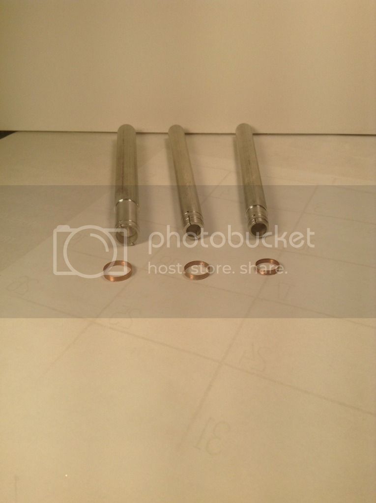
I began by measuring the O.D. and I.D of the kit part and then turned three mandrels out of aluminum rod to produce three rings of wound copper wire - one each to match the O.D. and I.D. of the kit part after allowing .018" for the wire and one to produce a ring centered
equidistant between the outer and inner ring.
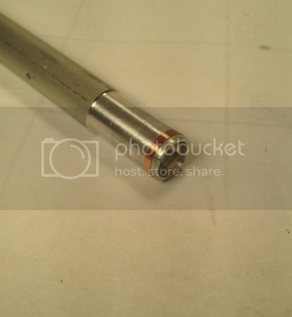
A small amount of flux was brushed on the wire and solder was drawn across a file and the filings then brushed on to the wire-
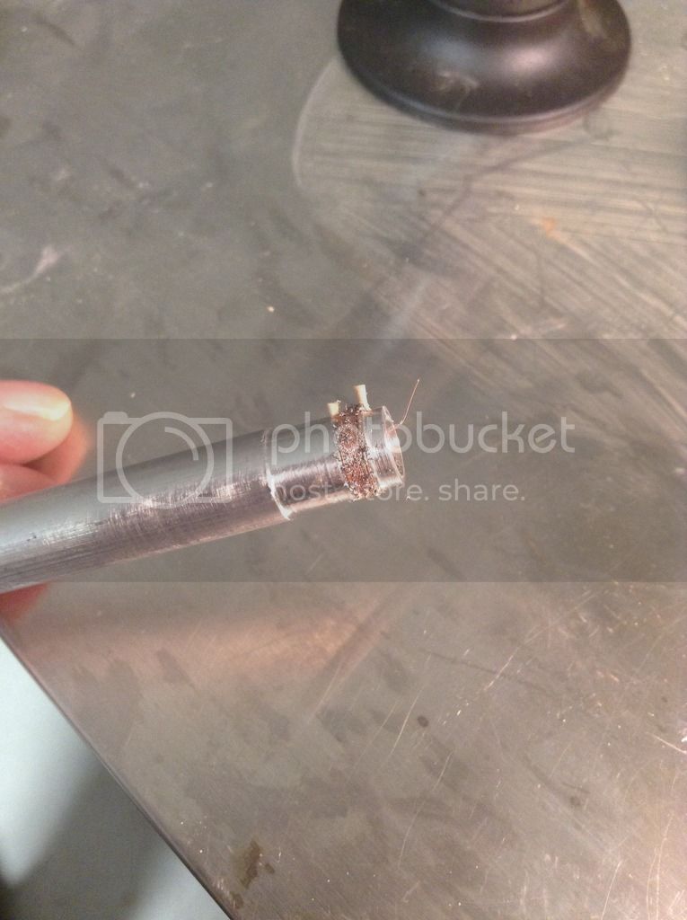
then torched -
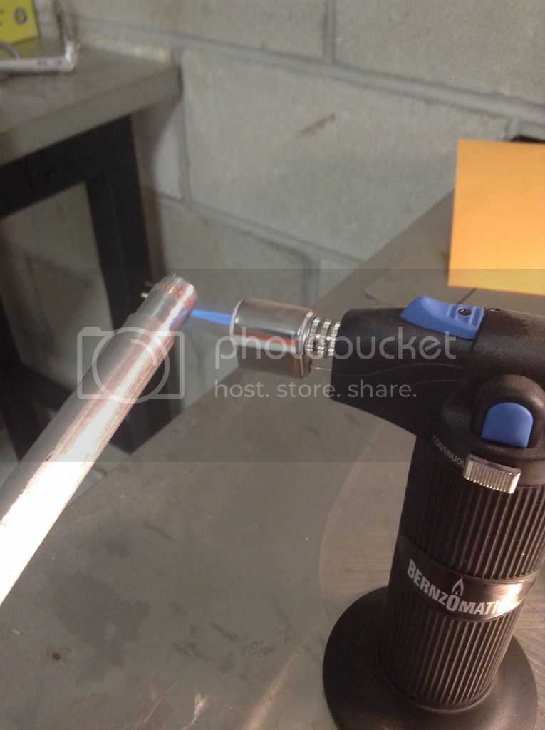
Here are the three mandrels and the three rings - I had to bore out the ends of the mandrels because in their solid state they had too much thermal mass and were acting like a heat sink preventing the copper from getting hot enough - suffice it to say that I had a few bond failures before I figured this out !

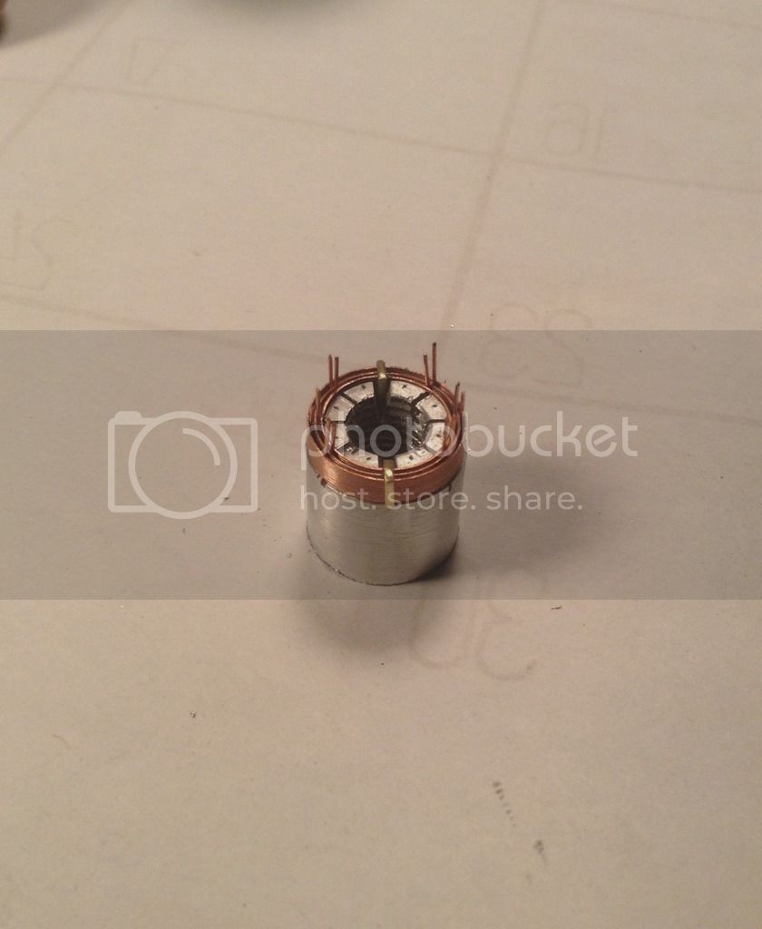
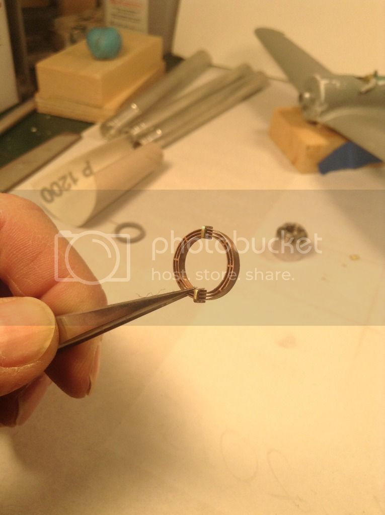
The prototype cooler rings are sweated together radialy with webs at 22.5 degree intervals with brass junction blocks 180 degrees apart at the top and bottom - As these engines are dry sump I believe the oil feeds into the cooler from the sump at the bottom of the crankcase and then circulates through the cooler before returning to the oil tank from the top juntion block.
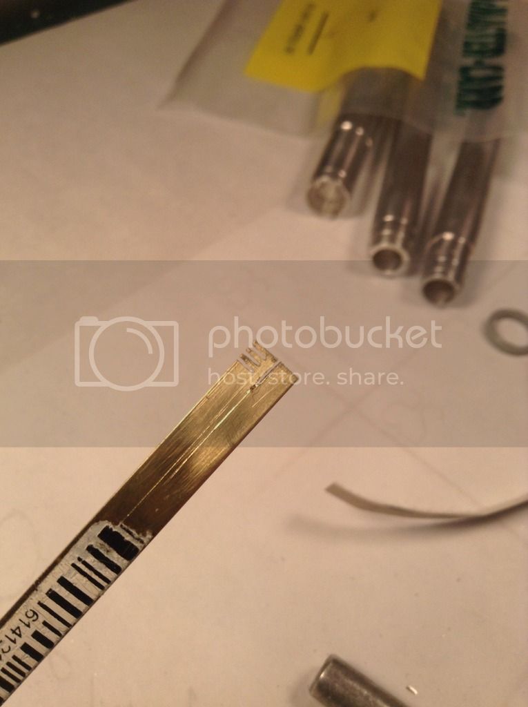
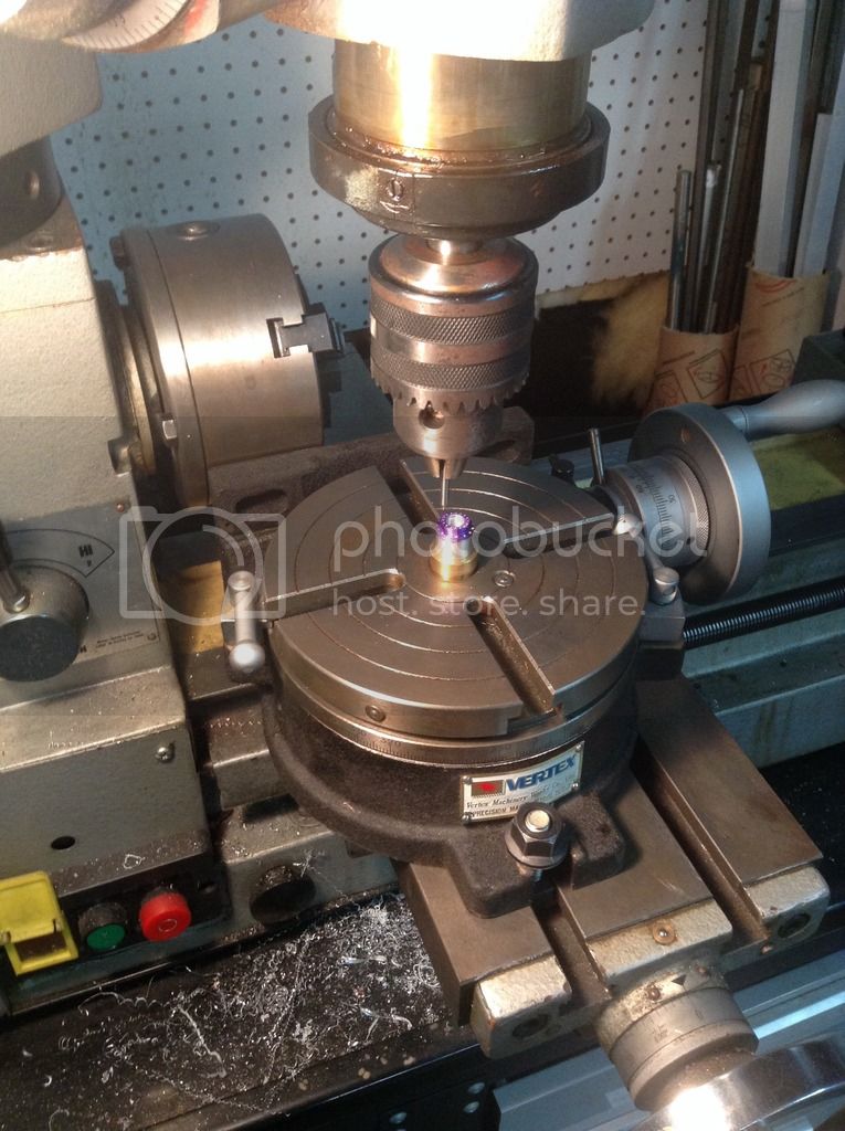
Joining the three rings I have made and keeping them concentric is going to be the difficult part I believe . I have turned up an aluminum hub and marked out the divisions for the spacers using the rotary table. I hope to saw slits through these divisions to hold drawn copper wire for the spacers and two brass pieces to represent the junction blocks. I did some testing with my different solders and I believe the electronics solder has a sufficiently lower melting temp so the soldered rings won't be affected-
Fingers crossed !

Here is the hub being marked out -
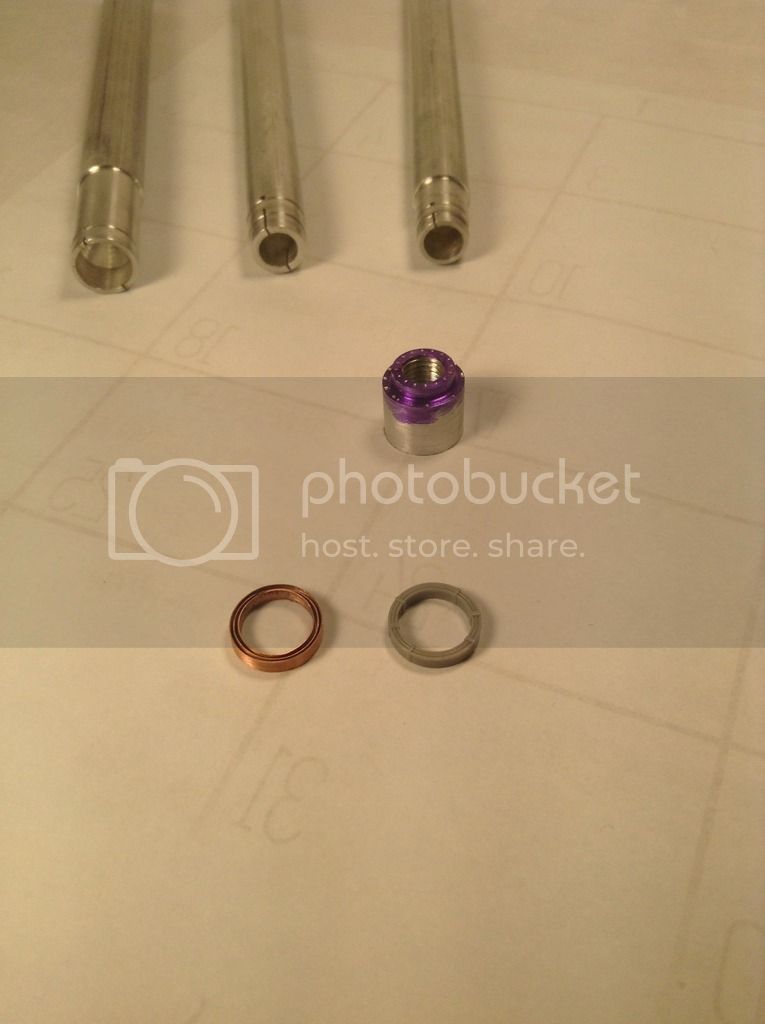
and here we have the mandrels, hub, the rings placed together concentrically and the kit plastic cooler -
More to follow and wish me luck - a lot of potential for heartache here !
Thanks for looking and as always, ALL input welcome !
Cheers - Richard


