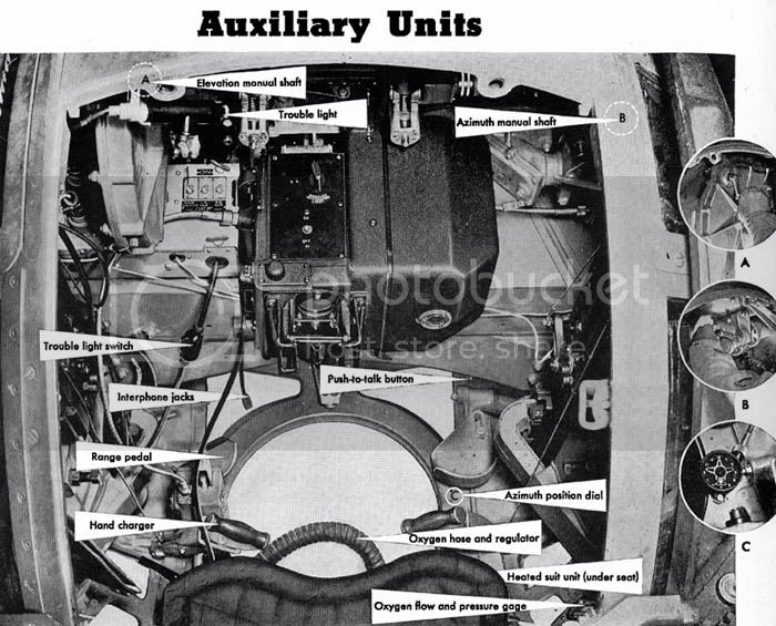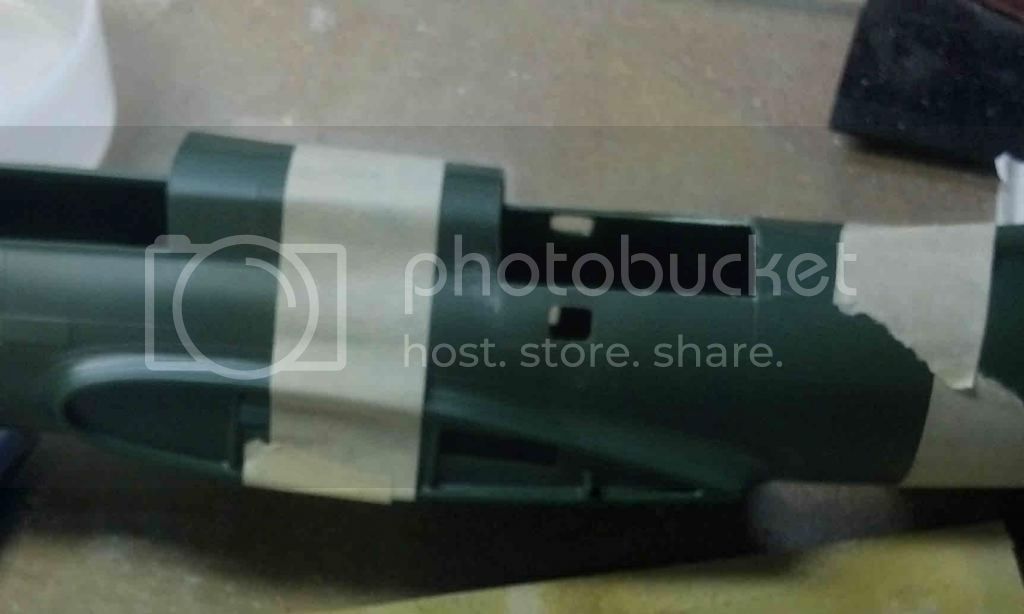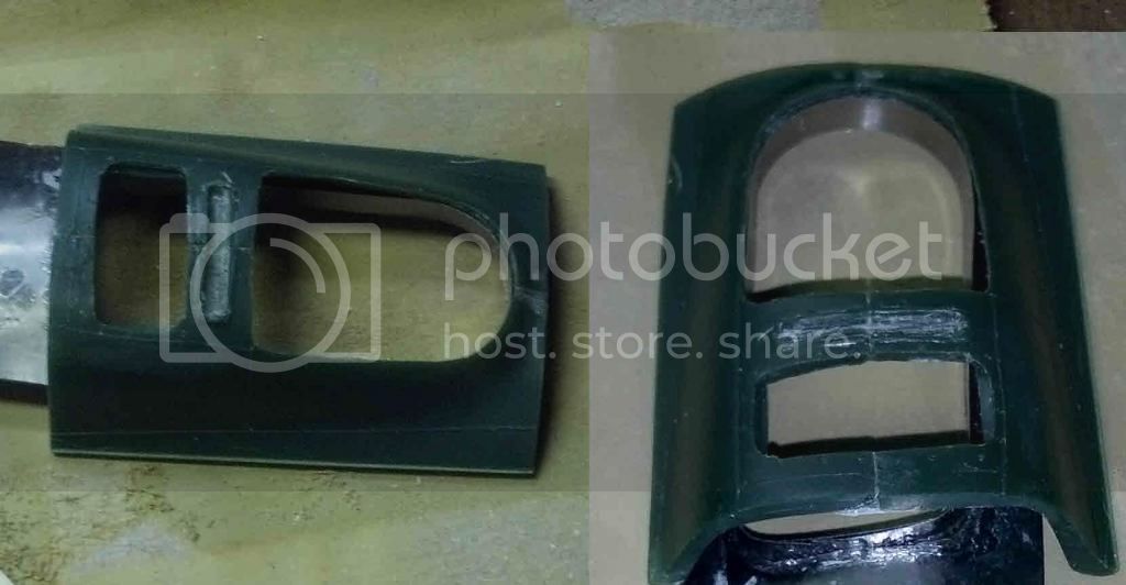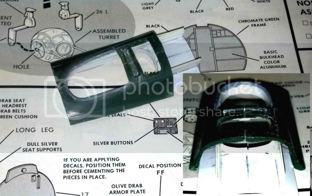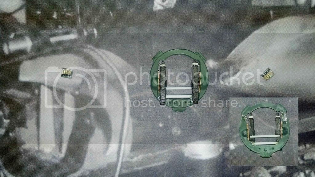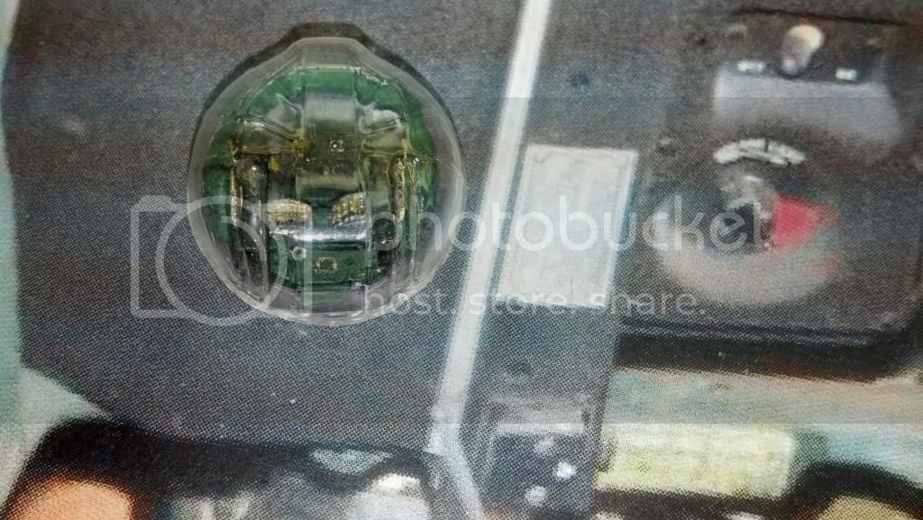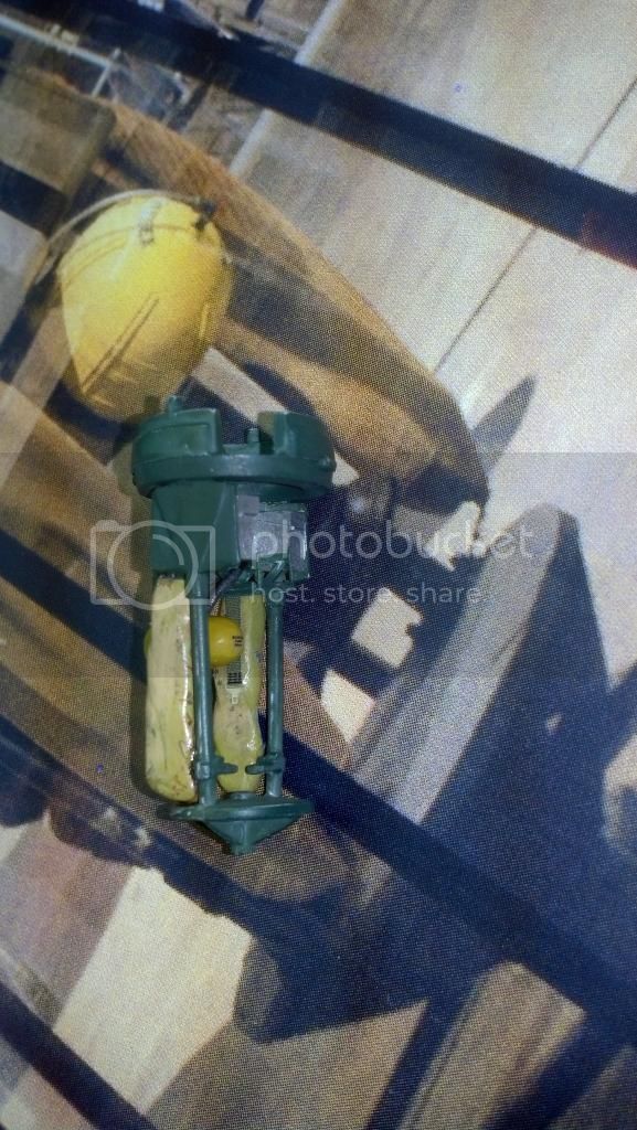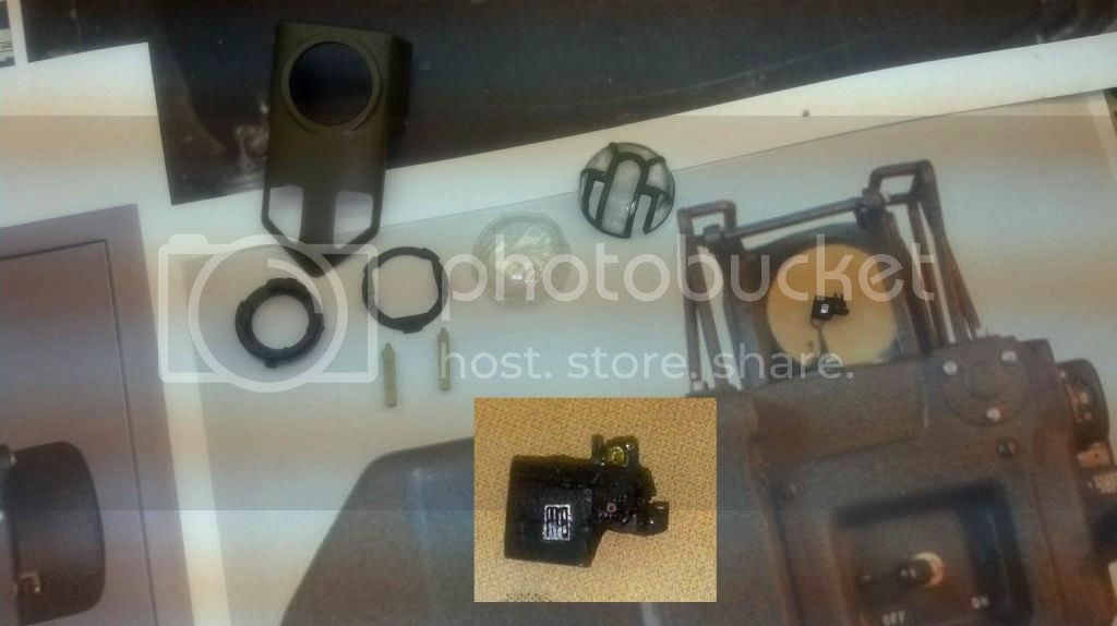
This is a brief update on my work on the top turret. Below you can see a collage of modified turret parts, mostly from thr Monogram G kit, against a background photo showing the rear of the Sperry K-3 gunsight, and an inset showing some gunsight detail.
You can see how I modified the shapeless kit gunsight -- from the rear. I didn't realize until the picture was taken that the data plate was a bit off-center. I will replace it with a smaller decal later, and also show you what the front and top of the sight look like after modifications.
Going back to the main picture, I removed the center from the top turret ring, where the guns, gun feeds and sight were. The resin gun bases pictured are from the Verlinden set: I already drilled out the holes in front for the Karaya metal barrels and blast tubes.
Next, take a look at the unpainted turret dome and compare it to the real thing, which is the last picture in the prior post. This part is from Bill Koster's excellent "B-17F Nose Job" set. It doesn't look like much unpainted, but when you compare it to the Revell kit part in the picture -- the one I built in the 1980s -- you can see how very different it is. Here is a better picture of Koster's work from his instructions. If you want to do an accurate B-17F, the Koster part is a must!
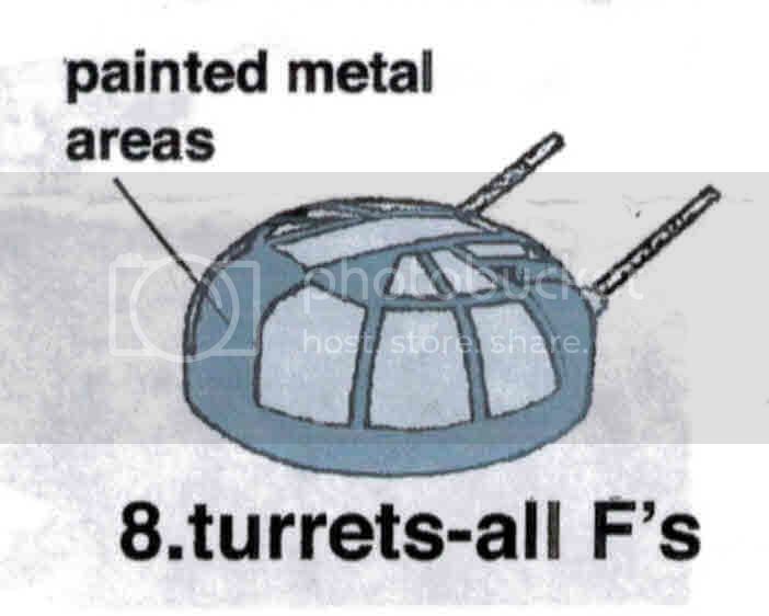
To free the dome from the vacuform backing, I cut it out leaving a 1/4 inch border around the edge. (None of that scoring at a 45 degree angle around the base for me: too dangerous.) Instead I put the part on a flat sheet of 320 grit sandpaper and sanded the base away with a light circular motion. After a while it thins to the point where it just cracks and falls away from the part. I do like this method.
Later this week I am meeting my friend from North Carolina and we will do some work on the two biggest challenges in the build. The first is the radio room roof assembly around the rear hatch that houses the .50 cal with a sliding U-shaped bracket. The structure is totally missing from the Revell kit. See below.
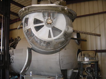
We are also going to work on the ball turret, outside and inside. Outside we have to add semicircles to the sides of the ball and restructure the holding bracket. Compare the two photos below:
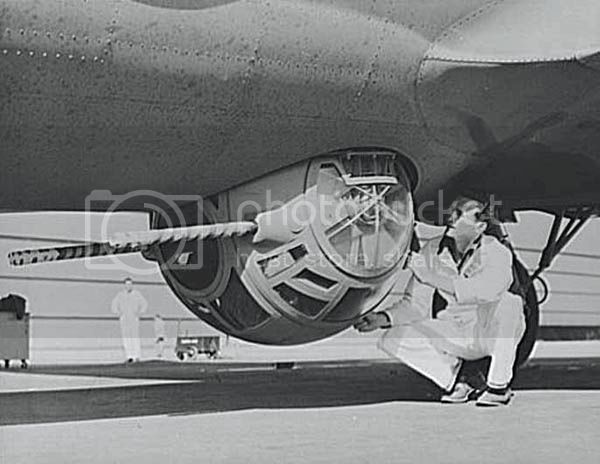
Above is the turret that "Luscious Lady" carried. What follows is the much simplified exterior side structure carried on later B-17 ball turrets.
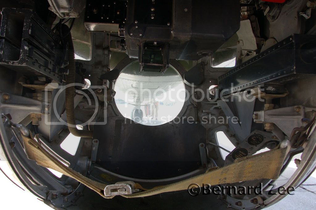
Finally, we will consider adding some detail to the interior of the ball.
Stay tuned!
World War II
Discuss WWII and the era directly before and after the war from 1935-1949.
Hosted by Rowan Baylis
1/48 B-17F Build - 303rd BGs Luscious Lady
Posted: Sunday, June 08, 2014 - 03:09 PM UTC
Posted: Monday, June 16, 2014 - 05:14 PM UTC
"Trip Report" Part 1
Well, I made my trip to North Carolina to visit my modeling friend (he wishes to remain anonymous) to get some "out of my labor grade" help on the B-17F radio room hatch cover details and U-shaped gun bracket; and some help on the exterior details of the early Sperry ball turret on "Luscious Lady": the one with the rounded sides. He and I also discussed detailing the ball turret interior. As you will see in my next post, he literally "opened the door" to that possibility.
The trip was a smashing success and I learned a tremendous amount. So I will walk you through the progress made now. This post deals with the radio room hatch and U-shaped gun bracket.
I was concerned about taking the actual fuselage I'm working on so took the Revell of Germany B-17F kit I have instead. You will immediately recognise it from the dark green color of the plastic vs. the OD of the older Revell issue.
You will also note immediately that one of the first things we did was decide to cut open the radio room roof (like the cockpit roof) so that we would have a template to measure the coaming and internal hatch-ceiling structure.
We started with some thin stainless steel sheet he had for the coaming around the rear hatch, because it can be cut just like styrene with a #11 blade, a ruler and geometric templates, and for a while it looked great. Note also that he hogged-out the deflector bay base. (Aluminum foil or styrene bar stock will clean that up later.)
However, the material proved too pliable and prone to creasing and bending when we tried to add strips to build up the coaming sides, and after almost a full day and evening messing with the metal we were forced to admit that styrene was probably a better choice.
I was beat that evening after a long drive and went to bed around midnight but my friend said he wanted to "study" the problem some more.
When I woke up next morning this is what greeted me:
You can even see where he put rivets in the border of the coaming like the real thing had! Note also that there is a pair of sliding rails for the U-shaped gun bracket.
The Pièce de résistance was the gun bracket itself. A picture is worth a thousand words.
The center part is the diamond shaped center of the kit part from which the straight edges of the part extending to each side have been clipped and bent copper wire substituted. (He even put a longitudinal cut to the diamond to simulate the fact that it actually is two plated enclosing a ball and socket swivel). The sliding brackets are just styrene bar stock, and the securing nuts come from his supply of HO "railroad bolts."
Here is the after hatch opening with the gun bracket test fit before sanding away the grey primer at the coaming edges. The fit is so good that it actually slides fore and aft on the rails!
And here is the completed subassembly compared with the real thing:
Needless to day I was quite pleased as Day 2 came to a close.
PS: I just notice that in the "real thing" picture above, there is a heavy, curved piece of armor just under the forward opening of the after radio room hatch. That I will add at a later point in the build, when I get to the radio room.
Joel_W
Associate Editor
New York, United States
Joined: December 04, 2010
KitMaker: 11,666 posts
AeroScale: 7,410 posts
Joined: December 04, 2010
KitMaker: 11,666 posts
AeroScale: 7,410 posts
Posted: Tuesday, June 17, 2014 - 12:38 AM UTC
Brian,
The level of detail that you're consistently increasing, just amazes me. The radio room roof detail is just beyond words.
Joel
The level of detail that you're consistently increasing, just amazes me. The radio room roof detail is just beyond words.
Joel
Thearmorer
Alabama, United States
Joined: June 17, 2014
KitMaker: 121 posts
AeroScale: 118 posts
Joined: June 17, 2014
KitMaker: 121 posts
AeroScale: 118 posts
Posted: Tuesday, June 17, 2014 - 09:04 AM UTC
Brian,
Concerning your PS about the armor fwd of the radio compartment opening, I wonder if what we're seeing isn't the plexiglas compartment cover in the "stowed" position. Reference your previous interior shot of the radio compartment looking fwd. In that shot there is nothing in that area that would correspond to an armor plate. Just my take on it, it seems an unusual spot for the extra weight. Excellent build in progress, I look forward to the next entry.
DRM
Posted: Tuesday, June 17, 2014 - 09:35 AM UTC
Thanks for your comment. I'll have to think about it and look at some other period photos. Will comment further on this after that.
Posted: Tuesday, June 17, 2014 - 01:30 PM UTC
Quoted Text
the level of detail
Again Joel, thank you for your kind words and moral support. I know I am trying something "big" here and maybe some discussion about similar efforts documented online is in order, both to explain the source of my inspiration and what I want to accomplish in this build blog.
For any modeler who knows 8AF history and builds mostly in 1/48, not having a buildable B-17F is like not having an H81-A2 ("P-40B/C") in quarter inch while being an AVG fanatic. It's just no fun dressing a P-40E or N up as if it was the earlier aircraft. You want to model accurately the airplane that did the fighting during the tough times. In the 8AF that's the B-17F. Period.
And yet, since the Monogram 1975 release of the B-17G, no kit manufacturer has taken the task on. The Revell F is basically an empty shell.
Paul Budzik recognized this in 1989 when he backdated a G to an F model. http://paulbudzik.com/tools-techniques/B-17%20Conversion/monogram_b-17_conversion.html . When I saw the original article in "Fine Scale Modeler" I almost died of envy. Ever since I have wanted to do a build somewhat like his, even if I started with the F kit. If you look at the article you'll see that his radio-room roof looks a lot like mine, although I doubt we got there the same way, and to my knowledge there is only one other modeler who has tried to replicate this feature.
Anyway, I am really trying not to do "the whole thing." I agree with you that creating a busy effect is good enough, because if you tried to replicate everything in 1/48 you'd go crazy. (At least I would). I will do enough detail in the bomb bay and the waist to be respectable, and to create the illusion of completeness. Some areas I'm not going to detail, like the wheel wells. Fuggedaboutit.
Because I was so frustrated in seeing Budzik's work, knowing I could never replicate it, I'm going to try to explain how the effects you and others see are done, should anyone want to try it.
The below picture shows that the coaming is not that hard. Just take some sheet styrene to create the ceiling, then flip the part right side up to trace the coaming cut out on the styrene from above with an indelible pen, then cut it out. You can then circle the opening with a vertical styrene ring and cut to fit and sand it down. Extra details can be added after that. Getting the dimension of the opening right and putting the ceiling piece in is the trick, IMO.
What my friend did to create the curved sides of the ball turret is even more fascinating. I'll cover that in the next post.
Joel_W
Associate Editor
New York, United States
Joined: December 04, 2010
KitMaker: 11,666 posts
AeroScale: 7,410 posts
Joined: December 04, 2010
KitMaker: 11,666 posts
AeroScale: 7,410 posts
Posted: Sunday, June 22, 2014 - 10:38 AM UTC
Brian,
I've been a big fan of Paul's since his PBY-5 swept the nationals. All I can tell you is that your skills and level of work is right up there with his.
Joel
I've been a big fan of Paul's since his PBY-5 swept the nationals. All I can tell you is that your skills and level of work is right up there with his.
Joel
Posted: Sunday, June 22, 2014 - 12:19 PM UTC
Quoted Text
Brian,
I've been a big fan of Paul's since his PBY-5 swept the nationals. All I can tell you is that your skills and level of work is right up there with his.
Joel
No comment but thanks anyway. To me there are three types of advanced modelers. I call them the "plastic workers," the "painters," and the "metal workers." Of course, great modelers have elements of all three in them.
The plastic workers are the folks who can mold their own stuff and show a creative talent in manipulating plastic, resin, styrene stock and other materials to produce something the manufacturer never intended. People who have talent in the plastic arts (such as sculpture, ceramics, etc.) frequently apply those skills to the hobby, with awesome results.
The painters are the people who are literally that, who know something about perspective, scale effect, lighting, etc. and apply those skills to aircraft models. I think of commercial artists and really good figure painters who transfer those skills to model aircraft. One guy I knew was a commercial artist at his employer, and his paint jobs were spectacular, even if his basic "building techniques" sometimes showed shortcuts.
The most exotic class for me are the metal workers, who usually have strong skills in plastic and paint, but take their creations to a whole other level of fabrication, planning and integration. What am I talking about? The following Halifax Mk. II in 1/48 is one of the most amazing things I have seen a modeler do. http://www.helmo.gr/index.php?option=com_deeppockets&task=catContShow&cat=24&id=1256&Itemid=35
I am putting together a post about the B-17 ball turret work in North Carolina, that will go up soon, but I am also messing around a bit tonight with the top turret.
Posted: Sunday, June 22, 2014 - 05:32 PM UTC
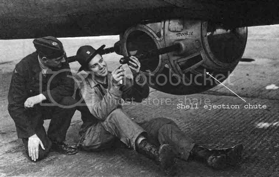
On to the ball turret. First some fresh views of it with some details that are frequently overlooked. First, a forward shot with the shell ejector chute flagged.
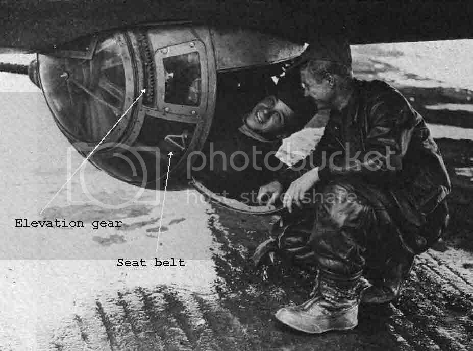
Next a shot of the rear with that complex turret side and--hey look!-- an external set of gear teeth showing for the elevation mechanism! Also, the left seatbelt.
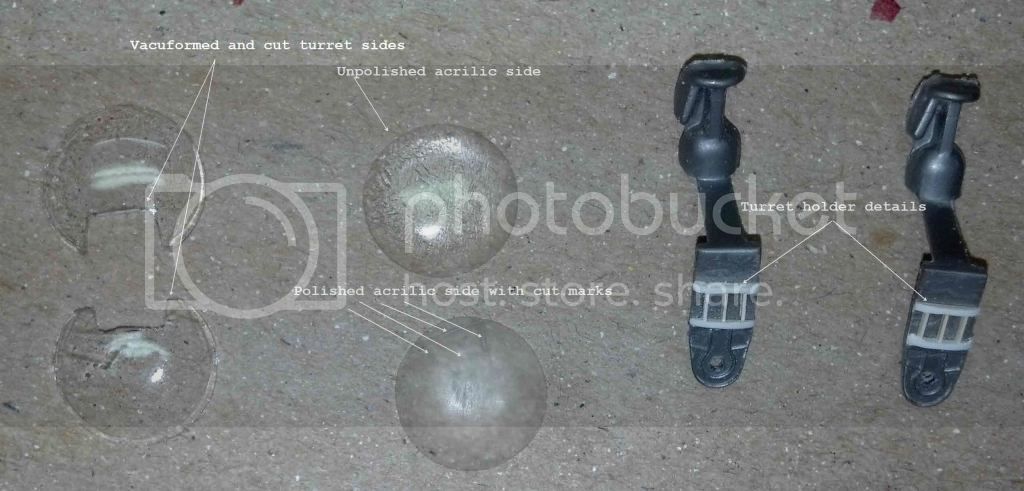
Here's what we did for the turret sides:
The final pieces to be attached to the turret sides -- after additional interior details are placed inside the "glass"-- are shown on the left. They were vacuformed over the acrylic curved sides in the center, which we originally were going to use for the sides themselves, but then changed our minds, and defaulted to using them as vacuform molds and a cutting pattern for the vacuform pieces at the top.
The big question is: HOW were the acrylic sides formed?
First, we decided to sacrifice my 1980s completed turret for the kit. We started with a hard sheet acrylic sheet and a razor saw. The sheet was deep enough to exceed the depth of the curved turret sides, and small squares were cut from the sheet and crazy-glued to the flat sides of the old kit turret.
Second, my friend belt sanded the acrylic to take a lot of the excess material off, especially on the corners of the squares.
Third, I was instructed to take a large file my friend had and start filing, moving around the acrylic from the edges towards the center. In a "you can't defy the laws of physics" kind of way, the filing direction created remarkably uniform hemispheres after application of a lot of firm but not overdone filing.
Fourth, we broke the turret apart and then pried the hemispheres off of the turret pieces. It was surprisingly easy. I then used sanding sticks to clean up the edges and the bottom of the hemispheres, and we polished one of them out with Novus plastic polisher to see if it would serve as the turret side itself. Our conclusion was that trying to cut this to fit the upper turret bracket (see bracket with details added, above right) and create space for the details inside the hemisphere below it, was too risky. Using the acrylic hemispheres as molds for vacuforming was the best bet.
I would not have believed the acrylic hemispheres could have been created using the above methods, but seeing is believing. It can be done without a fancy mold to pour the acrylic, etc. Hats off to my friend for some creative thinking on this.
Now a few words about the main turret itself.
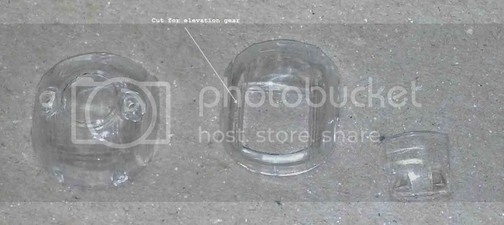
You can see that my friend cut the door out. I will position the turret rotated a few degrees off center with the door open so that one can look inside to see the details I plan to add. My friend also cut a slot on the left side for the elevation gear. For this he suggested that I get an old watch gear to cut and glue in place, and that's one excellent suggestion. I decided to go all "steampunk" on this and ordered a cheap lot off of ebay.
What you can't see, but what is there in the turret front, is the hogged out shell casing ejection chutes my friend completed. I will highlight those with a dark wash when completing the turret so they don't look like windows.
It will be quite a challenge finishing that turret! But, for now, I have another challenge to return to: detailing the top turret. I'll discuss that in my next post after I've made some progress.
GastonMarty
Quebec, Canada
Joined: April 19, 2008
KitMaker: 595 posts
AeroScale: 507 posts
Joined: April 19, 2008
KitMaker: 595 posts
AeroScale: 507 posts
Posted: Sunday, June 22, 2014 - 06:38 PM UTC
Great work!
I have a question for you:
One of the very few things I don't like about the Monogram B-17G is that the wings are a bit "wobbly"-looking in thickness when looking at them from the front. There should be one crisp straight line for the top and bottom surface from at least the inboard engine to the wingtip, and to the wingroot on the top as well, if memory serves... How do the Revell wings look in that frontal aspect? Do they look any straighter than the Monogram wings?
The funny thing is, I know these wings are fully interchangeable with the Monogram wings, hence my question...
Gaston
Posted: Monday, June 23, 2014 - 02:15 PM UTC
Well, I think the wings of both the Revell and Monogram kits are about equally "warped." When I saw it first time I was worried, but when you glue the wings together the sections seem to straighten out. That was my experience with my build in the 1980s, and taping the wings together now.
The only difference in the wings I can see is more finesse in the finish in the Monogram kit (true overall) and different slots for gluing them to the fuselage. Either way, I am going to have to do surgery on the joins because I am including the bomb bay.
Joel_W
Associate Editor
New York, United States
Joined: December 04, 2010
KitMaker: 11,666 posts
AeroScale: 7,410 posts
Joined: December 04, 2010
KitMaker: 11,666 posts
AeroScale: 7,410 posts
Posted: Tuesday, June 24, 2014 - 01:24 AM UTC
Brian,
Your description of the 3 classes of Advanced Modelers, is certainly well thought out. To me Paul is a combination of #1 & #3 because he's a master of both. Being a Dentist he has skills and specialized tools that allows him to create his masterpieces. Others just have talents and skills that the rest of us can just be in awe of. Me, I'm just a plastic model hacker, enjoying the hobby with no special advanced skills. My goals are simple and direct: Build the perfect OOB model. Detailing here and there for a little added interest. Certainly nothing on the level that you're building at.
I've seen a U tube video of an Italian modeler who spent nearly 10 years designing and building a working 1/8 scale Ferrari P312 race car. Everything works, runs, and operates exactly like the real race car. Naturally, he's an engineer, and has a home shop that allows him to create his master pieces.
You and your friend's lower ball turret is just a remarkable piece of plastic model engineering, as is the entire build to date.
Joel
Posted: Sunday, June 29, 2014 - 02:47 PM UTC
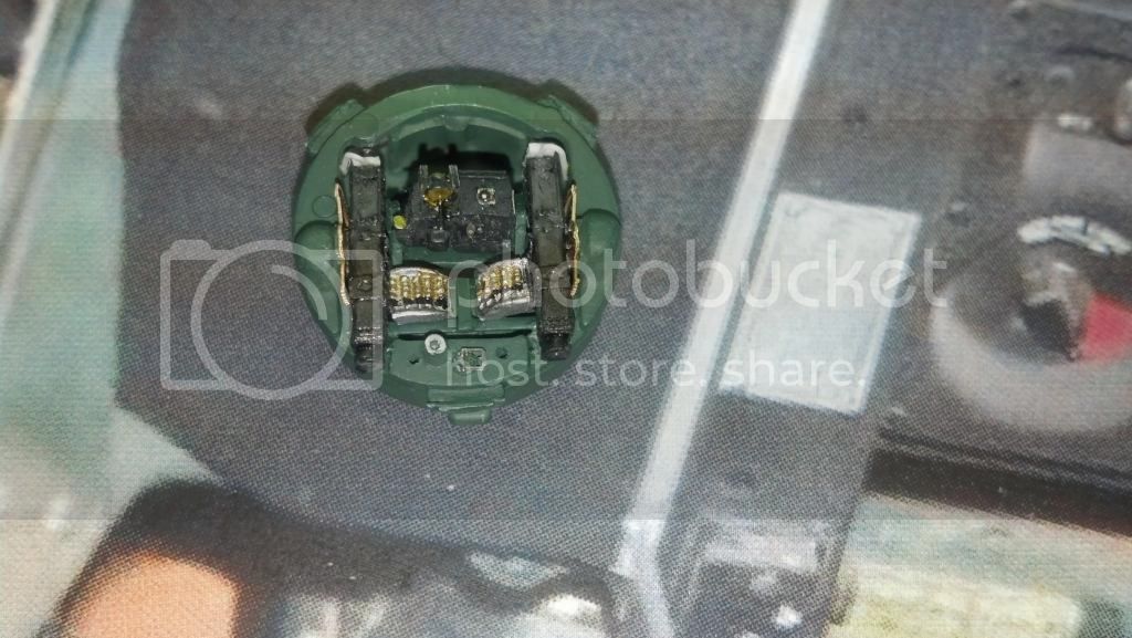
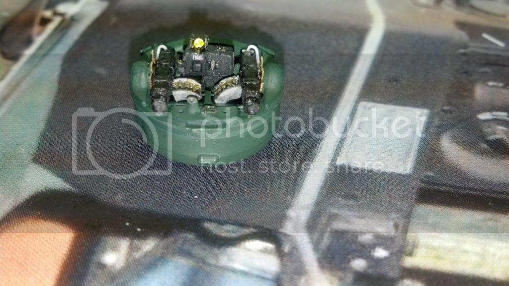
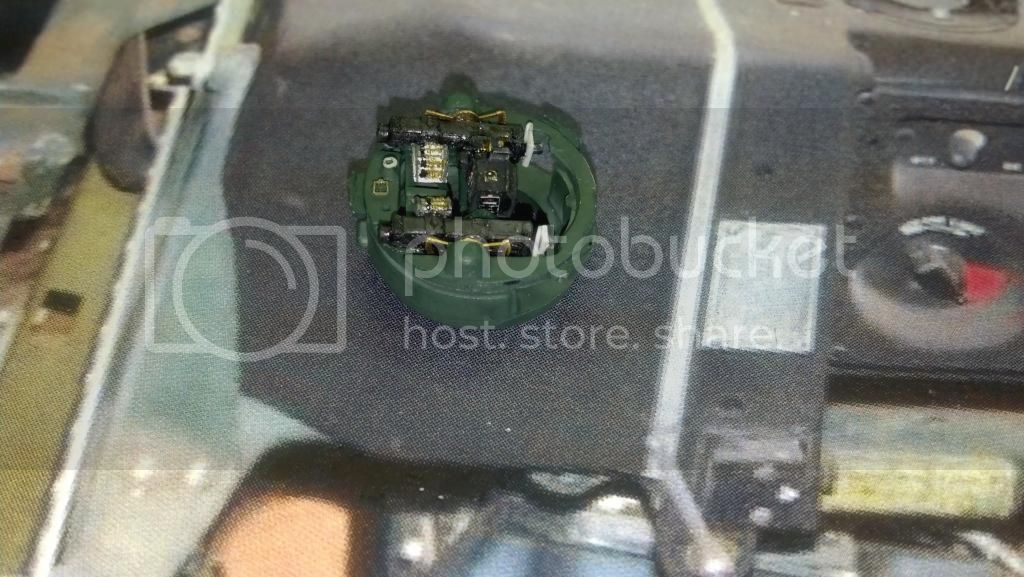
TOP TURRET - A START
It's taken me a while to refocus on the top turret after the North Carolina trip. However, after much thought on an approach to the additions, I started from the top down.
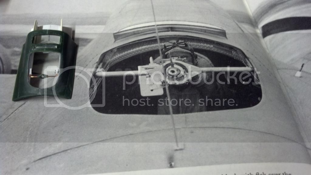
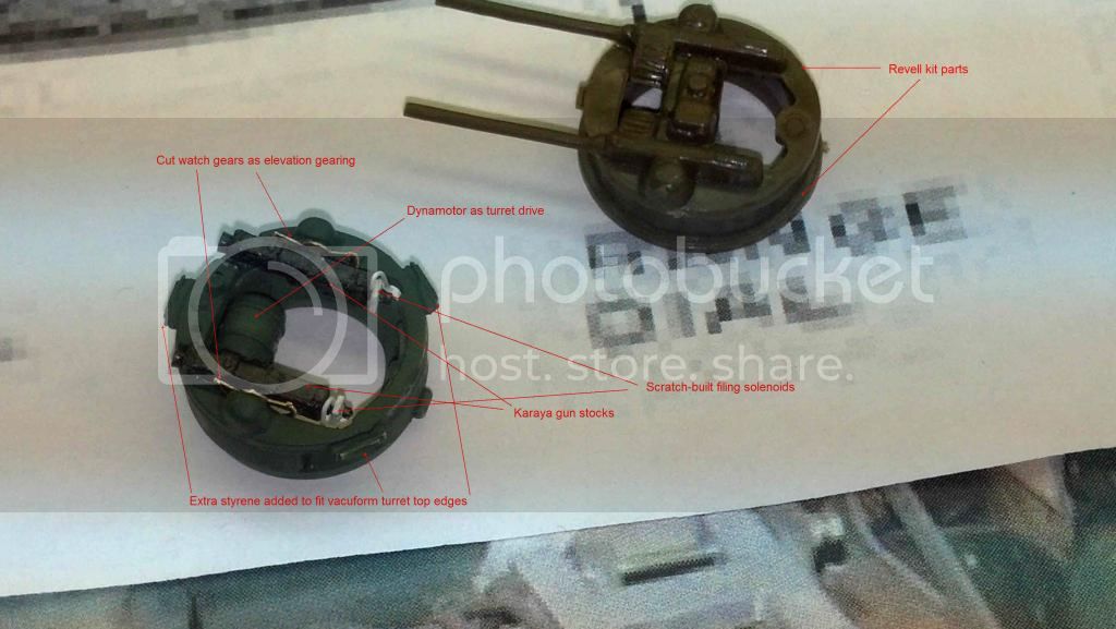
The first photo shows the Revell basic top turret assembly next to the modifications I have made to the Monogram G kit parts.
I spent far more time planning this than actually doing it.
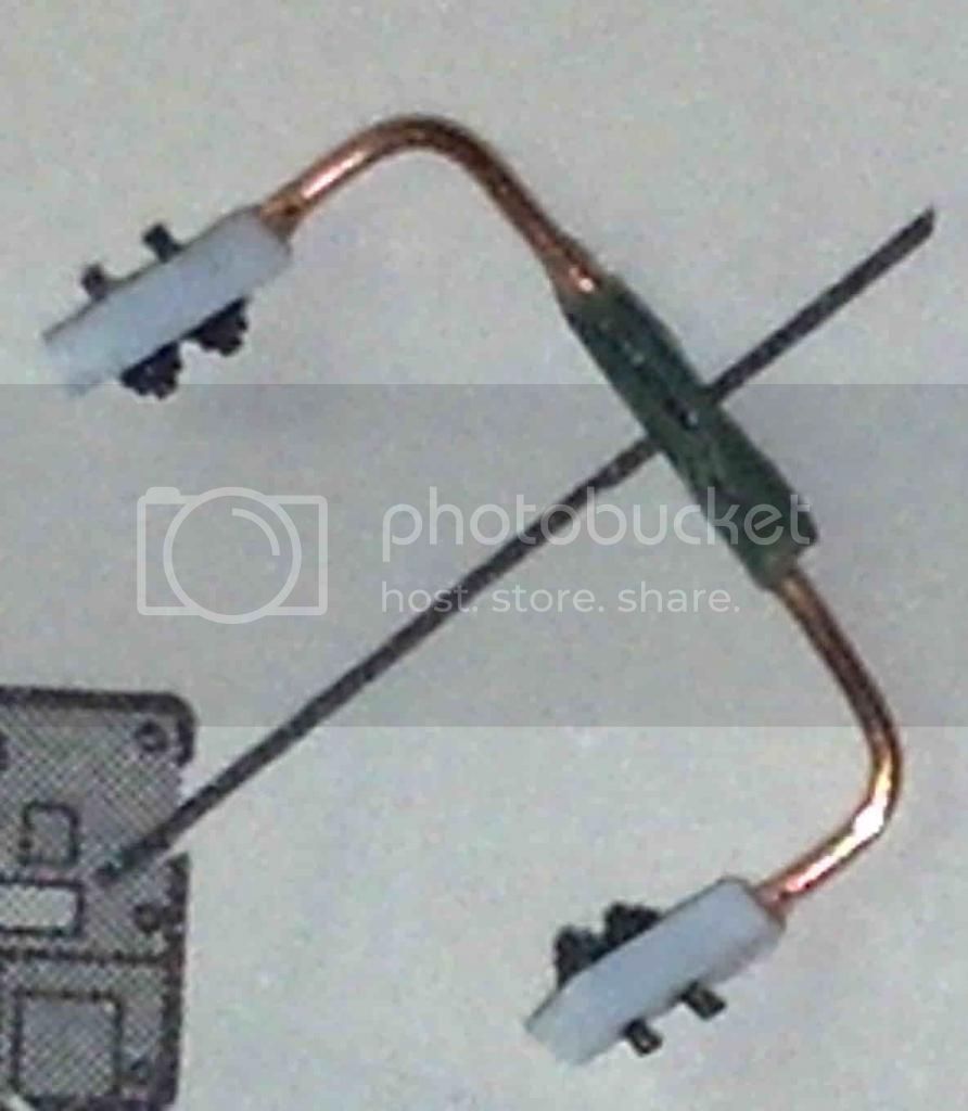
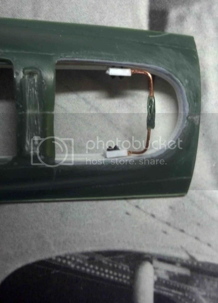
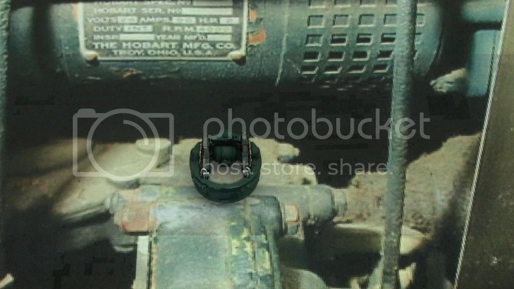
Below this photo are two more. The first is a close-up against "the real thing" to show that, "Yes, there is a drive motor in the front of the turret." I used an extra True Details cockpit floor "dynamotor" to represent it, and while most of it might not be visible when the turret is done, I wanted it to be there. (I also added a data plate in the middle of the motor using Mike Grant's ever useful WWII cockpit instrument and placard/data plate decals.
You can see that I also drilled some holes (for drive cables) and added some small details to the front of the turret above the motor.
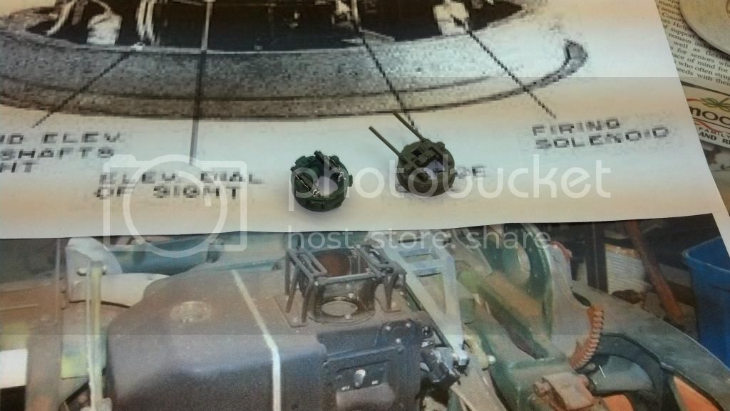
The next photo is there simply to show via the background image that these white firing solenoids at the gun butts aren't a figment of my imagination. Look above the parts and they leap out at you.
A brief note on the color. It's not "bronze green," but rather RAAF "foliage green," which matches the color in the pictures of turrets and other equipment far better than flat bronze green IMO.
Next time I'll add ammo feed trays (or at least the tops of them) between the guns and fashion a bracket for the gunsight.
Joel_W
Associate Editor
New York, United States
Joined: December 04, 2010
KitMaker: 11,666 posts
AeroScale: 7,410 posts
Joined: December 04, 2010
KitMaker: 11,666 posts
AeroScale: 7,410 posts
Posted: Tuesday, July 01, 2014 - 04:58 AM UTC
Brian,
Amazing.
Joel
Amazing.
Joel
Posted: Friday, July 04, 2014 - 01:15 PM UTC
TOP OF THE TOP TURRET
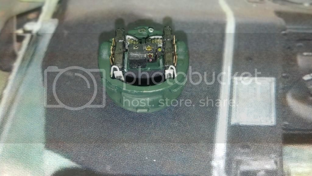
Well, I more or less completed the basic work on the top of the top turret. I'll show a work in progress pic and then what the top looks like with most of the bells and whistles added -- I still have some wires to put in, but that's for later.
It's not perfect, and bears the signs of a dirty ("weathered" from handling) build, but it's "good enough" for a view through the painted dome, and "I build for myself" anyway (he said defensively).
First, the gun ammo feeds actually are integrated into a rectangular, open bracket at the front. Here you see me starting to put that in with styrene bar in a top and bottom view. You can also see the gun feeds that I cut away from the Monogram kit parts:
FWIW, the ammo in the gun feeds is yet another area where the Monogram G beats the Revell F. The Monogram kit has bullet tips, the Revell just oblong shapes so you can't tell where the "front" ot the bullet is.
Here's a top view with the unpainted glass dome loosely placed over the turret ring:
Here's an "under the hood" look from the front so you can see the completed bracket for the ammo feeds:
Here's one with the sight, which is in fact slightly off center in the real thing.
Here's a side view.
And finally a view from the rear.
Close enough for government work, as they say.
From here I will be moving a level below to the V-shaped bracket for the ammo boxes, the boxes themselves, the two handed turret control handle and brackets for the oxygen bottle, regulator and hose.
After that it's on to the base, and those spent ammo casing bags, where I have a "he cheated" solution.
Gremlin56
Joined: October 30, 2005
KitMaker: 3,897 posts
AeroScale: 564 posts
KitMaker: 3,897 posts
AeroScale: 564 posts
Posted: Friday, July 04, 2014 - 05:34 PM UTC
It's a fascinating build to follow so far Brian, glad to hear the expression "I build for myself" used by someone else too Keep the photos coming,
Posted: Saturday, July 05, 2014 - 01:04 AM UTC
Thanks for the kind words, Julian. Since I'm not one of the Experten and score only an occasional "kill," I necessarily "build for myself," and prefer it that way. I don't enter the local IPMS contests either, at least not since I started building again.
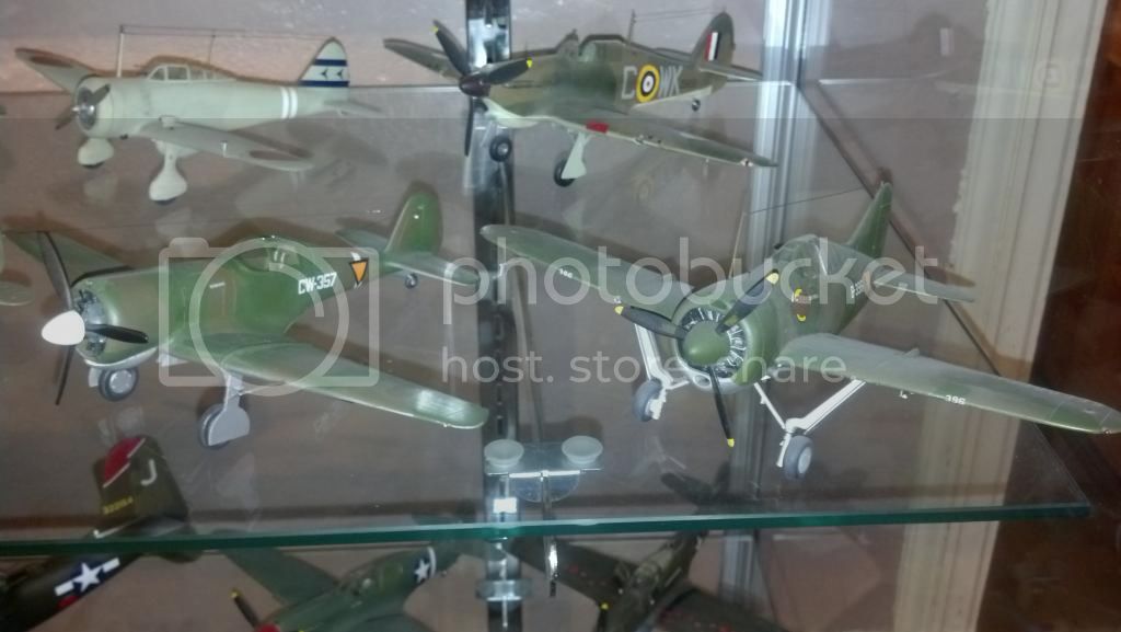
Since you're Dutch I confess to a soft spot for the NEIAF, and show off two 1/48 builds below. The early war in the Pacific is another major area of interest for me. The Hurricane in the background participated in the defense of Rangoon, 1941-42.
The CW-21B kit is still available, https://ncwebshop.de/epages/ncs244425151111.sf/en_GB/?ObjectPath=/Shops/44425151111/Products/48-P003 and was my first resin build. One of these days I will add an H-75A-7 to make it a trio. That's another long term goal.
Gremlin56
Joined: October 30, 2005
KitMaker: 3,897 posts
AeroScale: 564 posts
KitMaker: 3,897 posts
AeroScale: 564 posts
Posted: Saturday, July 05, 2014 - 02:39 AM UTC
Spot the Orange triangles
Actually a Brit by birth and took the Dutch nationality in my very early twenties, (getting on for nearly thirty-five years ago) .
Cheers Brian,
Actually a Brit by birth and took the Dutch nationality in my very early twenties, (getting on for nearly thirty-five years ago) .
Cheers Brian,
Posted: Monday, July 07, 2014 - 01:36 AM UTC
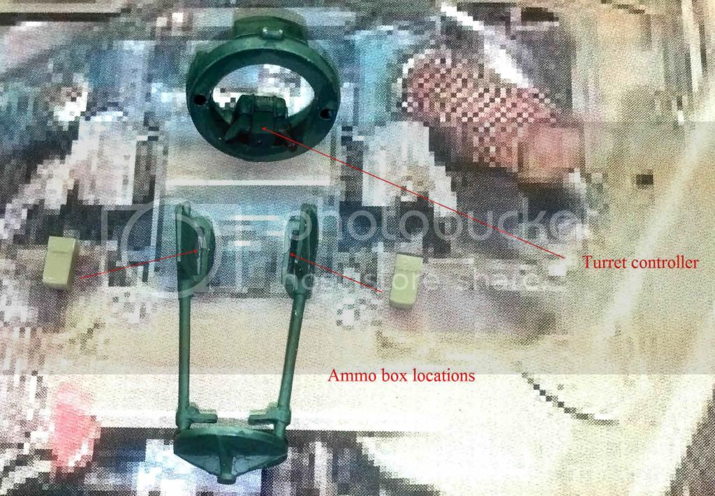
Just a short update to show the turret control installed below the electric motor, and generally where I'm "going" with the lower turret.
It would be madness to try and replicate everything in this area, even though it should be visible through an open cockpit window because I'm placing the turret in with guns facing aft. I am opting to go with one resin ammo box each at the inner tops of the stand part, and will fashion an inner holding bracket underneath the turret controller that will fan out to the inner sides of the ammo boxes, and also provide a base for the oxygen regulator and small oxygen tank at the bottom.
I'll have better pictures next time. More coming soon.
Joel_W
Associate Editor
New York, United States
Joined: December 04, 2010
KitMaker: 11,666 posts
AeroScale: 7,410 posts
Joined: December 04, 2010
KitMaker: 11,666 posts
AeroScale: 7,410 posts
Posted: Monday, July 07, 2014 - 02:47 AM UTC
Brian,
I know I keep on saying this, but Amazing just fits your build. The turret is just "mind Blowing". You really have to have lived through the 70s to understand that expression.
I just felt right from the start that your build would be something special, and it has been way more then that.
Like you, this time around in my modeling adventures, I too build strictly for myself. No more IPMS contests/conventions other then as a guest, nor local club or club contests. Strictly for my own enjoyment, and getting to share it online with my friends here on Aeroscale and ARC (my other modeling site). Of course I have a brother whose also an avid builder, so we share everything via online, and when we get to see each other.
Joel
Posted: Monday, July 14, 2014 - 05:11 AM UTC
Pardon late response. Thanks again for your kind comments.
Actually, the only other site where I have posted anything by way of build is also ARC. I did a build of French/French Vichy Ace Pierre Le Gloan's D.520 a number of years ago. http://www.aircraftresourcecenter.com/Gal9/8801-8900/gal8897-D520-ONeill/00.shtm
Interesting airplane, interesting man.
The B-17 turret is done except for exterior work on the glass dome and barrels, which are "final construction items." I will do a post with pics and commentary tonight, plus the inevitable "Why am I doing this?" ruminations.
Posted: Monday, July 14, 2014 - 06:58 AM UTC
TOP TURRET COMPLETED
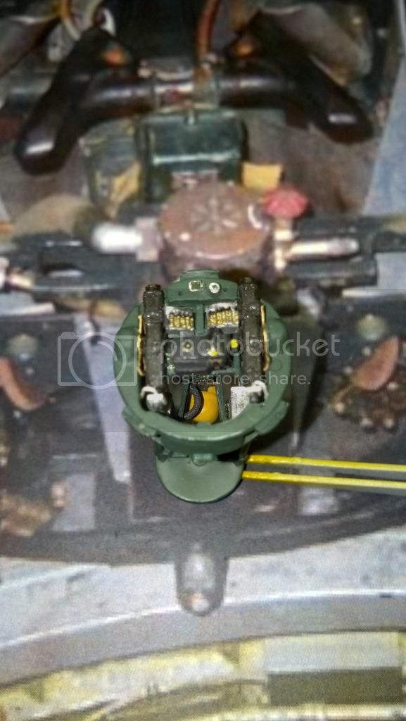
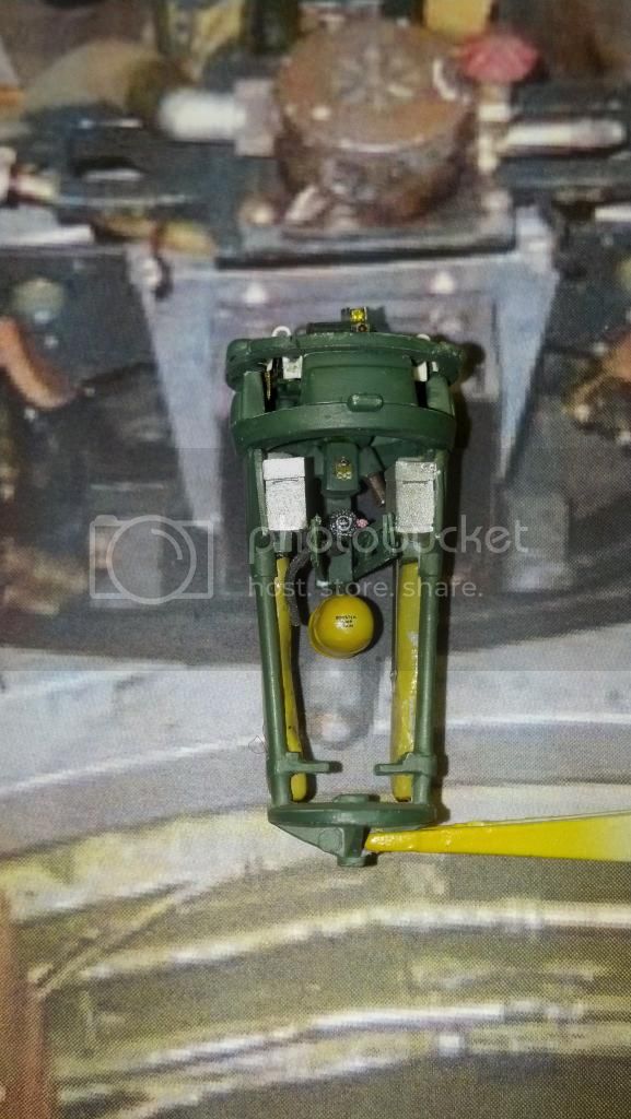
Got this done over the weekend. A long trip! Here are three photos.
Above is my preferred view. This is what most observers will see through the turret dome when the model is complete. Prominent inside are the oxygen tank, oxygen hose, and oxygen regulator in the middle above the tank.
Looking at the rear. Since the guns in the turret will be facing aft, this is more or less what the viewer will see looking in from the open pilots' windows. Yes, I do plan to open pilot's and co-pilot's windows, so one can look aft at a slight angle.
Let me list where the extra parts come from.
1. The turret controller handle is modified from the Monogram B-17G chin turret handle. Right side cut off and a brown "throttle" (think motor bike) cylinder handle added just like the real thing. Eduard Brass in the middle just a spare bit to dress up a blank space and "fool the eye."
2. Ammo boxes from Verlinden B-17G set.
3. Pedestal below controller just bar and cylinder stock.
4. Eduard Brass oxygen regulator from B-17G colored brass set; sits on small cylindrical stub glued to post below turret controller.
5. Oxygen hose glued into cylinder stub hole behind oxygen regulator is a MDC (Model Design Construction) accessory. http://www.modeldesignconstruction.co.uk/mall/productpage.cfm/ModelDesignConstruction/_mdcdt07/54274/Oxygen%20Hose%201mm%2F0.8mm%2F0.6mm
6. Bracket that oxygen hose curls around is just an HO fence "Plastruct" http://www.plastruct.com/ accessory bought at local hobby store and sanded down and cut to fit. Parallel part on other side. Grid work doesn't match the real thing, but some of these were open grids on real thing and this is there for "fool the eye" purposes. Orygen hose threaded through it is similar to pictorial depictions I have seen.
7. Oxygen tank is Monogram B-17G ball turret part. Obviously I'll be using more than one of these in the build. Decal from spares box.
Discussion of more details follows.
Side Shot
8. The spent shell casing bags were cannibalized from a Monogram B-25 turret part. I painted them a combination of Tamiya yellow-green and a Mr. Hobby yellow and washed them with burnt umber. The intention is to depict them as very well used and worn. The tops were cut off the B-25 bags so they would fit the B-17 part. You can see real thing in the background photo. "Close enough."
9. Finally, waist "seat belt" hanging down behind orygen bottle is from Eduard Brass B-17 seatbelt set.
This puppy is going in a small clear "baggie" till much later in the build, after fuselage halves are glued together, when I insert it into the separate cockpit roof part before gluing that on.
This turret was a challenge but an acceptable result (for "build for myself" me) and was achieved by a systematic approach. I seriously feel no magic is involved. Just workmanlike step-by-step thought and problem solving. Glad it's done, and hope this gives you some ideas.
Again, my objective is to do enough detail and busy work in a "generally accurate" configuration so that I "fool the eye" and create an appearance of completeness and pleasant detail. I feel it's a Goldilocks "just right" approach for this hard-to-see part of the model.
Next: On the the pilot compartment roof, then, the bomb bay.
Joel_W
Associate Editor
New York, United States
Joined: December 04, 2010
KitMaker: 11,666 posts
AeroScale: 7,410 posts
Joined: December 04, 2010
KitMaker: 11,666 posts
AeroScale: 7,410 posts
Posted: Monday, July 14, 2014 - 08:21 AM UTC
Brian,
The ball turret turned out incredibly well. Detail is everywhere. This is no "good enough, Goldilocks approach" to fool the casual eye. This is detailing at it's best. Sorry, but you earned the merit badge, so now you get to wear it
Joel
The ball turret turned out incredibly well. Detail is everywhere. This is no "good enough, Goldilocks approach" to fool the casual eye. This is detailing at it's best. Sorry, but you earned the merit badge, so now you get to wear it
Joel
Posted: Tuesday, July 15, 2014 - 03:02 AM UTC
Thanks again. Yes, I'm fairly happy with the top turret.
Saw your post comment re use of a cellphone to take pictures. I do that with a flash, but agree regular light with some light brightness/contrast editing works better and gives a truer impression of how it looks to the naked eye. The flash always reveals blemishes that are invisible to the Mk. 1 eyeball.
I need to start using natural light and spotlight lamps more.
Are you out on Long Island or Upstate NY?
Joel_W
Associate Editor
New York, United States
Joined: December 04, 2010
KitMaker: 11,666 posts
AeroScale: 7,410 posts
Joined: December 04, 2010
KitMaker: 11,666 posts
AeroScale: 7,410 posts
Posted: Wednesday, July 16, 2014 - 02:25 AM UTC
Quoted Text
Thanks again. Yes, I'm fairly happy with the top turret.
Saw your post comment re use of a cellphone to take pictures. I do that with a flash, but agree regular light with some light brightness/contrast editing works better and gives a truer impression of how it looks to the naked eye. The flash always reveals blemishes that are invisible to the Mk. 1 eyeball.
I need to start using natural light and spotlight lamps more.
Are you out on Long Island or Upstate NY?
Brian,
I live in Suffolk county, Long Island. To me upstate is like a whole different world. We're really just a suburb of NYC these days, specializing in way to much traffic.
Joel