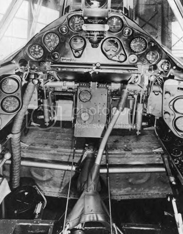
The cockpit of the F2A-3 is rather complicated, and is made up of several sub assemblies. I've already posted a picture of the basic unweathered IP/rudder peddle assembly. Next up is the seat sub-assembly.
I started with the correct seat as the kit contains the export version as well. Unfortunately, the seat is way too thick and chunky to have any kind of scale effect.

Rather then pour over the AM seats at the Sprue Brothers site, I went to work on the seat with #320 and #600 emery cloth. Once the sides, back, and front were nearly paper thin, I added the PE seat/back brace

I think that the seat now has a proper scale effect. The lever assembly just to the right of the seat is a bracket with the duel controls for raising and lowering the flaps, and raising and lowering the landing gear. The shafts do look a little chunky, but that's the way they should be. Just knobs were needed,which I made from several layers of white tacky glue.

Next up I built the seat sub-assembly. I left off the seat belts till after painting and weathering. The USN version doesn't have shoulder harnesses. Hard to believe, and I'm still researching that issue.

Before I painted the side walls I took a look at the scribing of the recessed panel lines, and they have a nice scale effect to them. But the rudder demarcation lines are just too shallow to give the impression that the rudder is a separate surface.

So using 1st my UMM #1 Universal scriber, followed by the Tamiya scriber, I deepened the recess so it looks like it goes all the way through. I still need to finish cleaning up the recesses.

The last sub-assembly that the IP sub-assembly attaches to is the central gas tank. The tank itself is rather crude once glued up, so I had to sand and fill with putty as needed. Naturally, I destroyed a nearly all of the surface details. Since you will won't see much of the tank once the fuselage halves are joined, I just replaced the major circle armor plates (?)with sheet plastic punched out circles.

Next up I painted the fuselage halves, the seat assembly, and the gas tank assembly with my Tamiya acrylic mix for Dark Dull Green. You can also see those two knobs painted semi gloss black.

Here's a picture of the IP/gas tank sub-assembly dry fitted. The fit is really pretty good. Actually, to get the IP in the correct orientation, you need to dry fit it, then glue the parts together. I had to do the same for the seat bulkhead as it's glued at a angle rather then straight up and down.

And now you're up to speed as to where I am in this most challenging build.
Joel